MichaelTM Posted April 16, 2023 Report Share Posted April 16, 2023 I'm so excited to get the v3. Along with the v2 I got from you previously it's gonna look so good and breath so much better! Can't wait. 1 Quote Link to comment Share on other sites More sharing options...
Xtra Posted April 22, 2023 Author Report Share Posted April 22, 2023 (edited) All the parts have arrived. I am posting photos of most of the parts needed to assemble the V3. This is the first run in 2023. It takes a lot of time and work to build the V3.it is the cost of these parts that sets the price of the V3. My labor is free. This is not all of the materials and parts, but it gives a good idea what it takes. Genuine Ford Parts are used wherever possible. The vacuum formed ABS. Ready to be made into the V3 Adaptor. Work will start on Monday, it will only be a couple hours a day, and I will post progress reports. Edited May 10, 2023 by Xtra 3 Quote Link to comment Share on other sites More sharing options...
Xtra Posted April 25, 2023 Author Report Share Posted April 25, 2023 (edited) And so it begins….. Decided to start with the lids and drill some holes. First thing was to drill something easy. The mounting holes for the Aux Air 6061 tube that the Flex Hose attaches to. As the build continues I will be showing work on one unit, but the same work is performed on the entire run. More work was completed on the lids today, but I ran out of time to post it all. Edited April 26, 2023 by Xtra 1 Quote Link to comment Share on other sites More sharing options...
Xtra Posted April 25, 2023 Author Report Share Posted April 25, 2023 (edited) The work on the lids continues with drilling more holes in them. This time for the Aux Air Intake input hole that the flex hose feeds fresh air to. It takes several different jigs to build the V3, and this is the one that is used to drill the Aux Air Intake fresh air input hole. The blue circles make assembly easy.as they help line up the lid. The lid is bolted to the jig Lots of blue painters tape to protect the lid from scratching The odd shape of the clamping board on the bottom offsets the lid into proper alignment with the drill Edited April 26, 2023 by Xtra 2 Quote Link to comment Share on other sites More sharing options...
Xtra Posted April 25, 2023 Author Report Share Posted April 25, 2023 The jig is clamped to the crossvise on the drill press and is aligned . It has to be aligned up and down, right to left, and in and out. The clamping board aligns the lid to the drill so that it is parallel to the base of the lid. 2 Quote Link to comment Share on other sites More sharing options...
Xtra Posted April 25, 2023 Author Report Share Posted April 25, 2023 (edited) Only after everything is aligned, double checked and locked down tight, can the lid be drilled. The finished hole, clean cut and ready for the next step. Edited April 25, 2023 by Xtra 2 Quote Link to comment Share on other sites More sharing options...
Xtra Posted April 26, 2023 Author Report Share Posted April 26, 2023 Tomorrow I will cut out the Adapter blank from the vacuum formed ABS. Perhaps even a new short video of the process. 1 Quote Link to comment Share on other sites More sharing options...
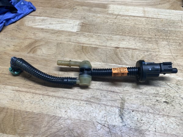
Willy41 Posted April 26, 2023 Report Share Posted April 26, 2023 I'm looking to buy v2 intake cover for 2016 ford edge sport? Possibly this Breather? Let me know thx leo 1 Quote Link to comment Share on other sites More sharing options...
Xtra Posted April 26, 2023 Author Report Share Posted April 26, 2023 As promised was able to cut out the Adaptor blank from the ABS. . First thing to do is drill two mounting holes. This is what it looks like after removing the blank from the ABS Video of how it is done 5 Quote Link to comment Share on other sites More sharing options...
Xtra Posted April 27, 2023 Author Report Share Posted April 27, 2023 I need to take a break for a few days as I caught some kind of bug. While I am not bedridden I am not well enough to work around power tools safely. I hope to be back at it next week at the latest. It is not Covid I tested negative. 1 Quote Link to comment Share on other sites More sharing options...
Xtra Posted April 27, 2023 Author Report Share Posted April 27, 2023 On 4/26/2023 at 8:30 AM, Willy41 said: I'm looking to buy v2 intake cover for 2016 ford edge sport? Possibly this Breather? Let me know thx leo Check your private message Quote Link to comment Share on other sites More sharing options...
Xtra Posted May 2, 2023 Author Report Share Posted May 2, 2023 (edited) Feeling better and got back to work on the Adapter today. Edited May 2, 2023 by Xtra 1 Quote Link to comment Share on other sites More sharing options...
Xtra Posted May 2, 2023 Author Report Share Posted May 2, 2023 (edited) Finished the second cut trimming all the Adaptors today . Before and after the cut, before finishing on the belt sander This is what is removed. It sets the correct height of the adaptor, and removes the flange around the edge. Edited May 2, 2023 by Xtra 1 Quote Link to comment Share on other sites More sharing options...
Xtra Posted May 2, 2023 Author Report Share Posted May 2, 2023 (edited) New much shorter video This video shows the process of how the second cut is made. Each step requires a different jig. At first, before I had jigs made, I would draw a line then cut wide and hand file and sand to the line. This had to be done during the design phase. Creating jigs that could produce repeatable accurate results was critical to the V3 project. It took a lot of time and work to get to this point where there is a complete set of V3 jigs. But it was worth it, the jigs are a huge timesaver and increases the quality of the V3. Making The Second Adaptor Cut... Trimming to finished Height. Edited May 3, 2023 by Xtra 2 Quote Link to comment Share on other sites More sharing options...
Xtra Posted May 3, 2023 Author Report Share Posted May 3, 2023 This is the final cut on the Adaptor. It now has been cut out of the ABS Vacuum Form sheet and is taking on the final shape. There is still a long way to go before it is a useable part. 2 Quote Link to comment Share on other sites More sharing options...
Xtra Posted May 5, 2023 Author Report Share Posted May 5, 2023 (edited) Although the third cut is the easiest to make. It requires the most amount of hand finishing of the 3. This is done to provide the maximum air flow and least amount of resistance. Edited May 5, 2023 by Xtra 2 Quote Link to comment Share on other sites More sharing options...
Xtra Posted May 5, 2023 Author Report Share Posted May 5, 2023 (edited) The next step is to clean up the third cut, it takes about 45min to an hour to complete. . This return lip must be removed for the intake to move air smoothly with no restrictions Before and after. The clean up is done with these three tools. Edited May 6, 2023 by Xtra 1 Quote Link to comment Share on other sites More sharing options...
Xtra Posted May 6, 2023 Author Report Share Posted May 6, 2023 (edited) The right angle air disc sander removes most of the material. But leaves a rough finish Using the razor to scrape the ABS cleans up the tool marks. The finished and polishes edge. Before and after. This completes the shaping of the Adaptor. Edited May 6, 2023 by Xtra 3 Quote Link to comment Share on other sites More sharing options...
Xtra Posted May 8, 2023 Author Report Share Posted May 8, 2023 The clean up of the Adaptor. This completes the process of cutting and shaping the Adaptor from the ABS vacuum formed sheet. 2 Quote Link to comment Share on other sites More sharing options...
Xtra Posted May 8, 2023 Author Report Share Posted May 8, 2023 (edited) The next step is to add the edge protector. This not only gives a finished look to the Adaptor, more importantly it seals the Adaptor air tight to the high density foam gasket on the lid. This edge guard is the best I could source with grips on both sides in the middle and metal clips molded into it It is cut to length and the Adaptor edge is cleaned before installing Ready to trim to length. It is easy enough to cut the material, but I only get one shot at it . Cut to short and the Edge guard has to be tossed. Cut a fraction to long, and when it is trimmed, more offer than not the edge is frayed making for a sloppy joint. This one I nailed spot on; The finished edge protector installed. Edited May 8, 2023 by Xtra 2 Quote Link to comment Share on other sites More sharing options...
Xtra Posted May 8, 2023 Author Report Share Posted May 8, 2023 (edited) Now, flip the Adaptor over and install the gasket that seals it to the bottom of the OEM air box once installed. The high density foam gasket. This lip that the gasket adheres to O.D. is made smaller so that when the gasket is installed the O.D. is correct and it will fit tight and seal into the OEM air box.. The Adaptor with top and bottom gaskets installed. Ready for the next step... installing the clips and latches. It is now taking shape and looking more like a part. Edited May 8, 2023 by Xtra 1 Quote Link to comment Share on other sites More sharing options...
Xtra Posted May 8, 2023 Author Report Share Posted May 8, 2023 (edited) On 4/26/2023 at 8:30 AM, Willy41 said: I'm looking to buy v2 intake cover for 2016 ford edge sport? Possibly this Breather? Let me know thx leo Willy41 Ihave sent you an PM and offered you a great deal. To view it, click on the envelope icon at the top right corner of this page next to your name. To anyone interested in a V2. I have a few Carbon Fiber material V2 remaining and these are the last of them. The CF I have been using is no longer available and I am selling the ones I have at below cost to make some needed space. Edited May 9, 2023 by Xtra 1 Quote Link to comment Share on other sites More sharing options...
Xtra Posted May 10, 2023 Author Report Share Posted May 10, 2023 (edited) Time to add the Tabs to the Adaptor. It is easy, but I have to be carful not to make a mess. The bottom half of a brand new OEM air box was cut up and sacrificed to make another jig for the Adaptor.. Converting the OEM air box into a jig insures that the tabs will be set correctly. The jig is taped down tight to the Adaptor to lock it into position, and to insure it does not move while working with it. The glue I use melts the ABS creating a weld when dry. The 3 Tabs installed waiting to dry. Edited May 10, 2023 by Xtra 1 Quote Link to comment Share on other sites More sharing options...
Xtra Posted May 10, 2023 Author Report Share Posted May 10, 2023 (edited) The "J Hooks" are attached next while the jig for the Tabs is still in place. I call them J Hooks because of their shape. The J Hooks installed. They are used to give the bottom half of the OEM air box something to clip to. You are looking at it upside down as compared to when it is installed in the car. The completed bottom of the Adaptor with the Tabs, J Hooks and gasket installed. Edited May 10, 2023 by Xtra 3 Quote Link to comment Share on other sites More sharing options...
Xtra Posted May 14, 2023 Author Report Share Posted May 14, 2023 (edited) Now it was time to test fit the Adaptor to the OEM air box. Checking to see.... 1. How well the Tabs align 2. How well the high density foam gasket seals 3. How tight the J hooks clip in. 4. How tight the Adaptor fits to the OEM air box . If there is any wiggle or slop 5. If the Adaptor sits flat, and even Edited May 14, 2023 by Xtra 2 Quote Link to comment Share on other sites More sharing options...


Recommended Posts
Join the conversation
You can post now and register later. If you have an account, sign in now to post with your account.
Note: Your post will require moderator approval before it will be visible.