


Dukhaykh
-
Posts
51 -
Joined
-
Last visited
Content Type
Profiles
Forums
Gallery
Posts posted by Dukhaykh
-
-
On 11/2/2023 at 4:36 PM, DistractedDev said:
My first question would be in what format does the OEM camera send the data, and is the new camera compatible? If it's something like a standard composite signal then it should be doable.
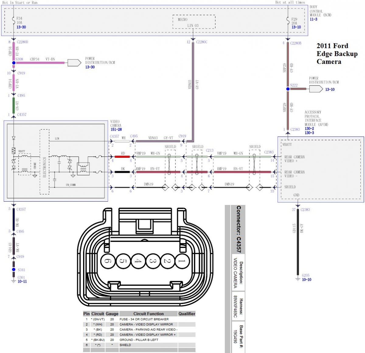
In your diagram, the FUSE (GN-VT, pin 1) should be your positive power (12V) and the GROUND (BK-BU, pin 5) your ground. I would check with a multimeter before hooking up anything to these.
The naming on the others is a little confusing. Looking at the diagram and not the connector, the Red and Black wires run to the APIM, carrying your video signal (plus a shield). I don't know what the White wire running to the BCM is for, unless it causes the signal to be mirrored (flipped horizontally), but this is a complete guess.
Hopefully this gets you started, and someone else will chime in with better info.
Many thanks for your time and support.
You are right on first point you mentioned about the signal format and compatibility. I figured out how to connect the camera cables with the OEM cables but somehow the video quality was not good enough. I ended up by wiring new cables to the new Android screen directly and it is working perfectly.
-
 1
1
-
-
?
Hey there,
I want to connect an aftermarket camera on my OEM previous camera plug. Any ideas where I connect the power and video wires!
I also found digram for Rear plug wiring diagram to help in this case.
Any support would be appreciated.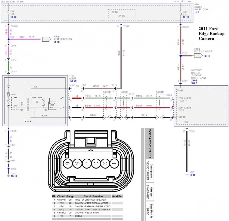
-
Your right,
Update;
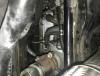
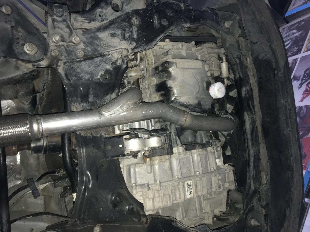
I did remove the rear did and its axels. After that I balanced both my rear tires.
Now everything is okay ??
attached how the car looks like without dif and axles ?
Next project will be removing the PTU.?
-
3
-
-
Hello,
My Edge AWD, I took off the drive shaft to make it runs as a FWD. I am wondering now if it’s possible to remove the rear differential & axles without issues?! If it’s possible, are there any possible effects on car stability & traction etc;
Thanks in advance ☺️ -
Thank you all for your great advices.
Hmmm,What about just installing one of the v6 turbo?! My be a rear mounted one. My main goal is to gain some power around 50hp ?
-
I am thinking to change my engine soon due to many problems. But I want to know is it possible to drop a Taurus Sho engine on 2014 Ford Edge ?
-
12 hours ago, omar302 said:
This post includes a how to for doing the opposite. It might give you some idea how to do what you need.
Thanks a lot Omar,Very glad to see these posts definitely these info will help me. ?
I have a hope that this issue can be fixed by only programming the steering wheel module.
will keep you updated. -
10 hours ago, omar302 said:
I had the same idea on my previous 2011 MKX. Had a topic about it here with some wiring diagrams & component locations with help from members. Short answer, I did not do it. There is a wiring difference and you'll need to route the wires for it to work.
Thank you Omar for your feedback. Will read the post you shared and see what I can do.
-
I have a 2014 SEL Edge. I have installed an Edge Sport steering wheel with (+/- Paddle Shifters).
I have currently shifters (+/- buttons on the shift lever). After the swap, unfortunately I figured out that the Paddle Shifters on the steering does not work!
Any idea how to get them work by using FORscan maybe? Do I need to make wiring modifications?
Appreciate any input on this. Thanks.
-
On 2/18/2020 at 2:55 PM, Gadgetjq said:
You could certainly give it a try. If it doesn't work then nothing gained but nothing lost either.
Using FORScan go to the following address. Write down your current settings before making any changes:Change Power Point Time Out (H/M/S)
BCM
726-39-01 **** xxxx xxxx Power Point MaxTime Cfg (seconds converted to hex)
Use this spreadsheet link. Adjust the timeout you want in line 3, note hex in first column, change BCM **** accordingly.
Tried that out but I it was very bad idea.
Unfortunately this way didn't work and now I can't return it to the factory values!
I keep getting error when I hit “Write”: "[17:12:41:891] Service procedure has been interrupted".
After communicating with FORScan Support they replied;
QuoteHello,
It was very bad idea to manage 2014- Edge configuration using 2015 F-150 spreadsheets as their BdyCM module configurations are *completely* different. 2015+ F-150 has the same BdyCM configuration and 2015+ Edge, and 2014- Edge has the same configuration as 2014- F150 but these 2 BdyCM are completely different. Recommended way to manage module configuration in FORScan is Module Configuration function that allows to manage module configuration in human friendly form (list of parameters). Last version of FORScan has Power Point configuration parameter available for your car this way.
As for the parameter you actually changed, it is PATS Timed method. You have disabled PATS TIMED method so now FORScan or any other scanner, including dealerhsip, will be unable to program PATS in your car. This parameter can be changed in only one direction and cannot be changed back by security purpose (BdyCM returns security error when you try to return it back). It is not a drama if you are not going to program keys. Unfortunatley, at this moment we don't know how to fix this kind of problems (hope get this knowledge in the future).
:(
-
Thank you @omar302 for your reply
This is a very disappointing ?
-
Hi,
Can I adjust the time of the Ford Edge 12v powerpoint timeout in 2014my?
Would like the 12 volt power socket to go off after a set time, currently it's on permanently, any idea of this can be done ?
Thanks
-
Thank you for your feedback,
I am thinking also to find out some Mods by Forscan May be!
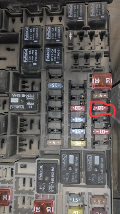
I usually take off the ABS fuse especially during race ? because I can see the difference in power ✈️ .
I have driven my car for almost a year without any problems. I even installed a switch inside my car connected to the fuse to turn it off/on easily ?
The problem with the fuse when you take it off the ABS system will shut off too.
I am thinking now to use my current switch setups on the back clutch instead of using the fuse.
Fuse box attached;
-
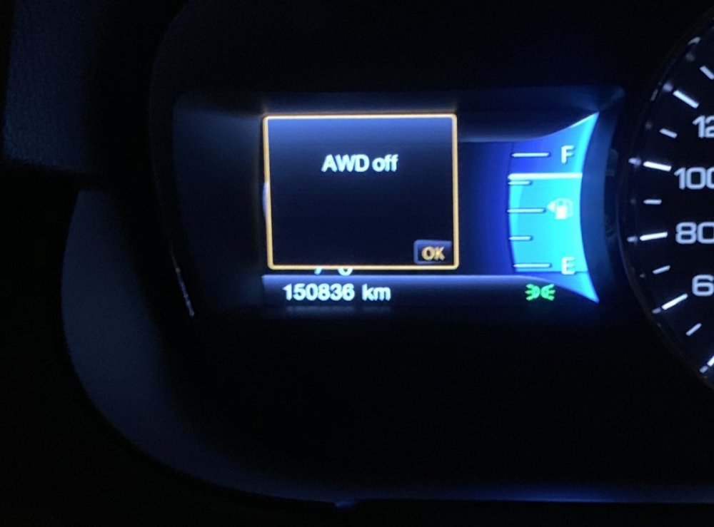
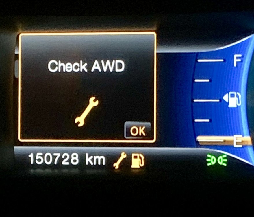
I tried also to pull the fuse for ABS and I got different msg on the dashboard as you can see below: AWD off
But as above picture, when I pull the back switch I got msg: Check AWD !
I don’t know if the first alarm means the ptu is off completely!
-
1
-
-
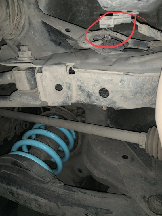
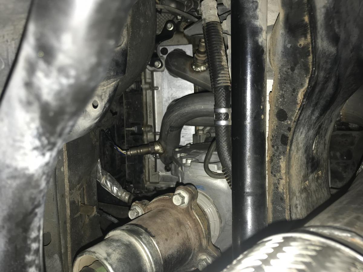
19 hours ago, WWWPerfA_ZN0W said:
The connector should be at the front part (ATC) of the RDU, which looks like this. The connector is most likely on the top side.
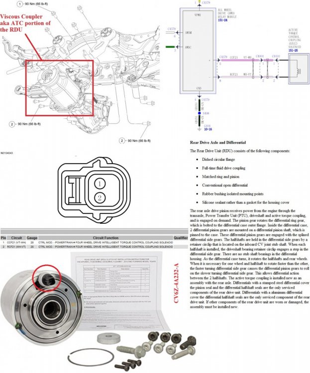
Thank you for your great information,
I found the connector on the same place you described above and pulled it out. It is showing now on dashboard lights saying Check AWD. Now its FWD only.
The question now, Is the ptu now still working and moving the drive shaft? If yes is there a way to stop it too ?
-
1
-
-
Just now, Dukhaykh said:
I tried to find the connecters but with no luck ?
any other suggestion?
I also did Pull the AWD fuse and it turned off but it also turned off the ABS and traction control!?
-
I tried to find the connecters but with no luck ?
any other suggestion?
-
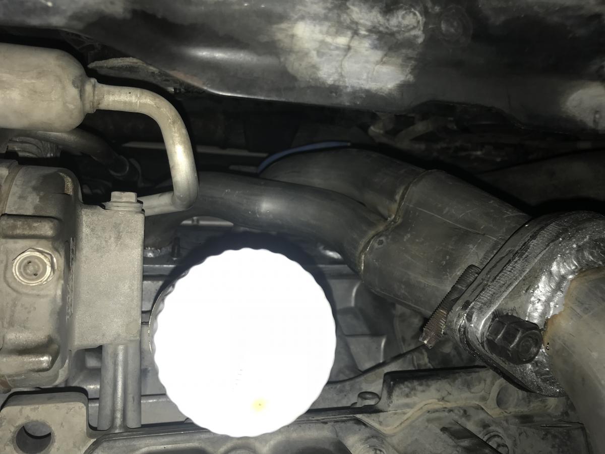
Its the same part. It is called "Vapor Canister Purge Valve".
I changed mine about month ago costs only around $25
-
Thank you for your feedback,
will try to find out the connector place ?
-
1
-
-
My 2014 ford Edge is equipped with AWD, i wanna turn AWD off and just use FWD temporary, Is there any way that i can turn AWD off?
-
A friend of mine did something with the fuses and made the AWD comes OFF (Dashboard lights says AWD OFF) and FW only works now without even removing the driveshaft! that means this thing is also controlled electrically.
-
1
-
-
Removed the driveshaft on my AWD and now it’s FWD ??.
-
1
-
-
Yes you are right the sound too low you have to insert the speakers ? inside your ears ?
Yes sure will keep them still new and as I know its so expensive.
-
1
-
-
Yes I already had exhaust cat back system and I added headers today from the engine outputs to the beginning of the cat back.
I like the exhaust sound now way better ?
Sound here;
https://www.instagram.com/p/BpXTneBFLCJ/?utm_source=ig_share_sheet&igshid=lssedzkphc14
By the way please follow me on instagram?

-
1
-


Wiring Aftermarket Camera in OEM plug
in Accessories & Modifications
Posted
Many thanks for your support and providing these valuable insights.
Regarding the installation process, I found different way on the Youtube and it worked well with me without the need for drilling or removing the Ford emblem.