


Wubster100
-
Posts
631 -
Joined
-
Last visited
-
Days Won
24
Content Type
Profiles
Forums
Gallery
Posts posted by Wubster100
-
-
Ambient Lighting
The ambient lighting subsystem consists of the BCM, and the Light Emitting Diodes (LEDs) located within the floor console, front and rear door panels, instrument panel and front and rear footwell areas. The ambient lighting is operational when the ignition is in any state other than OFF (the exception is when it is used in conjunction with the illuminated entry/exit features), the headlamps are on and the outside ambient light level is low. The BCM provides the voltage to the ambient lighting system, while the touchscreen ( FDIM) is used to cycle through the different color variations or turn the ambient lighting feature on or off. A LIN circuit is routed from the BCM to all of the Light Emitting Diodes (LEDs). There are 3 Light Emitting Diodes (LEDs) (red, blue and green) housed within each LED assembly. By illuminating various color combinations, the Light Emitting Diodes (LEDs) are able to produce different colors of ambient light.
The APIM uses software to monitor the user interface from the touchscreen. Based on the ambient lighting system selections made using the touchscreen, the APIM sends ambient light color request and ambient light intensity request messages over the communication network for color and brightness settings. The BCM retains the last color and brightness setting between uses.
For 2021+ the factory option is single color Ice Blue.-
 1
1
-
-
On 3/22/2026 at 7:06 PM, Brian r said:
Can you control your cupholder lights from the screen?
Yes, I am able to.-
1
-
-
My 2021 2.0l (Built after the PCM software was updated):
PCM - Powertrain Control Module
Part number: K2GA-12A650-CFA
Calibration level: M2GA-12A650-RE
Strategy : M2GA-14C204-RE
Hardware type: KK1A-12B684-HA -
You can change the temperature and fan speed with the steering wheel switch
-
1
-
-
I want to get IPC climate control working
-
1
-
-
SlaveExists_ALM_Cfg
It should be 726-65-01 xxx*-xxxx-xx
0 = absent 1 = present-
1
-
-
19 hours ago, WilkiST said:
Don't tell me i have to take the whole BCM out of the car, open it and solder/whatever new connection inside:) Then another question to you guys - how the heck to take it out? Or even how to have some access to BCM? I saw BCM during installation of HEADLAMP SWITCH - it is so deep under the dash and there is zero room for hands not mentioning any manipulation around connectors!
You do not need to remove the BCM or solder anything. Instead, to add a wire, you unplug the connector from the BCM, then you can take apart the connector, and push a new pin into it. You can access the BCM by reaching up under the dash, and you can remove the small cover in the front that is right below the headlamp switch.
19 hours ago, WilkiST said:5. Adapting the whole system to make it work - will it work straight away after the connections are made or some adaptation/programming is necessary? ForScan - how, what modules, etc - but for the moment i need to win points 1-4...
Program with FORScan. Changes in BCM to enable rear fog lights. And IPC to enable the indicator.-
1
-
-
1 hour ago, Brian r said:
Can I get the menu on sync by
changing the apim before the cup holders or wire from bcm is installed
Yes, you can enable it on screen. I will try to find the changes needed.
-
1
-
-
1. Yes add a new wire into the BCM connector and run it to the cup holder.
2. Yes. I think I got power from the auto start/stop switch.
3. What year do you have? SYNC 4 or SYNC 3? There will be more changes. There is a change in the BCM to enable the LIN for the lights. There are changes in the APIM to enable ambient lighting and to select multicolor or single color.
I did not make any harnesses. I just soldered and tapped wires. I did not use a harness for the cup holders, I just used small jumper wires / breadboard wires into the pins of the cup holders.
-
The ones for the back seat if you have them.
-
1
-
-
Still waiting on ssm 53966. 8 months absolutely no updates.
-
I don't see how the PSCM AsBuilt is the same from the 2020 F-150 and the 2019-2024 Edge.
-
I started doing some research, and there appears to be many models that the radar could be pulled from that look compatible like Explorer, Ranger, Mustang, F-150, F-250, Transit, Transit Connect, Navigator, Aviator, Corsair, Nautilus, and more.
The firmware flash, if needed, is probably easiest with FORScan, an extended license, and a quality supported adapter. And also a battery charger. -
-
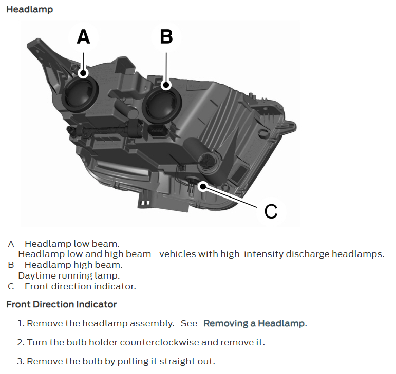
What do your headlights look like? Do you have the adaptive headlights? Both part numbers that you listed are for the non adaptive headlights. The non adaptive headlights use halogen bulbs that are replaceable. The adaptive headlights use led turn signals that are not replaceable.
-
-
11 hours ago, sc00by said:
Looking at the assembly, it appears that there isn't a bulb to replace
The headlights that you listed are both non adaptive headlights. These headlights should have a dual filament halogen amber bulb. Front direction indicator: WY21W (21 Watts).
-
KT4Z-13101-C is only a partial headlight housing. It does not include all parts. It is missing the Lighting Control Module that is the metal box underneath the headlight.
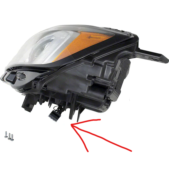
KT4Z-13008-AZ is the composite headlamp assembly. It includes the Lighting Control Module.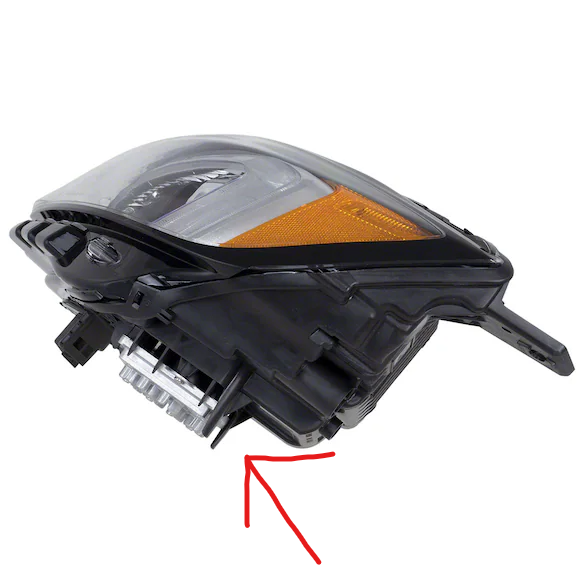
-
The fog lights use 20 gauge wire. They are just small LED lights. If you try to draw more power, the BCM will trip.
The BCM utilizes an Field Effect Transistor (FET) protective circuit strategy for many of its outputs, for example, lamp output circuits. Output loads (current level) are monitored for excessive current (typically short circuits) and are shut down (turns off the voltage or ground provided by the module) when a fault event is detected.
If the lights use 300 watts at 12V DC, it will draw about: 25 amps.
Current = Power / Voltage. 300 W / 12 V = 25 amps (often more at startup).
Instead, you should run new wires, fuses, and relays.-
2
-
-
The vehicle already had the wiring from the BCM to the front bumper connector, so I did not have to install new wires into the BCM.
-
8 minutes ago, Daban said:
Directly can i add four front sensors and connect to BCM then works ? It means does not need calibration for touch screen?
There is no calibration, but you need to program it to enable the sensors. -
Yep. Search:
site:fordedgeforum.com whatever you want to search here
-
1
-
-
-

Auto start/Stop Stopped working
in 2019-Current Edge & Nautilius
Posted
Use the fuel economy display in the cluster, and go to auto start stop, and it will tell you why it is off.