


Haz
-
Posts
1,568 -
Joined
-
Last visited
-
Days Won
437
Content Type
Profiles
Forums
Gallery
Posts posted by Haz
-
-
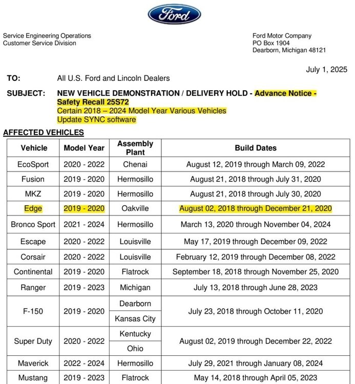
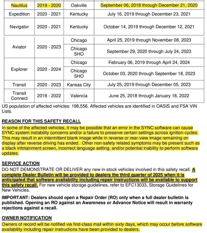
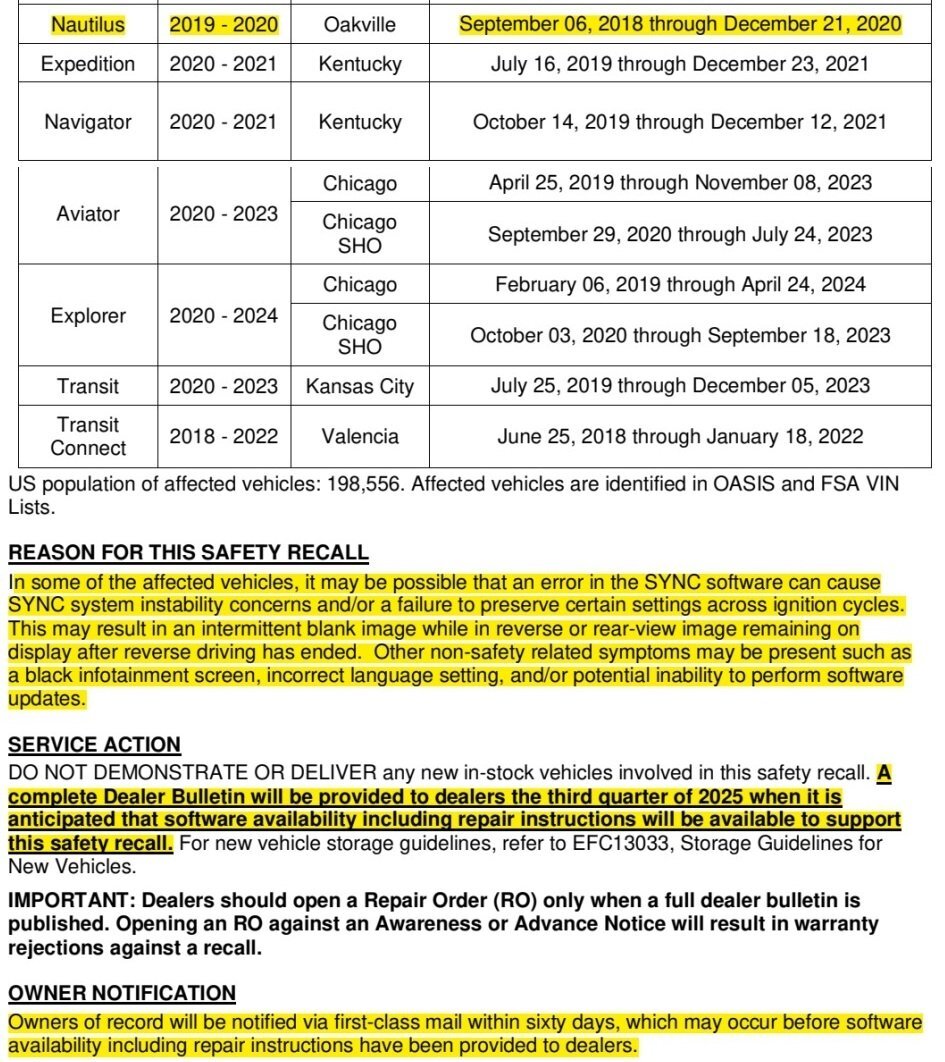
*** This is an Advance Notice -- This post will be updated when the Full Dealer Bulletin is released ***
-
 3
3
-
-
Confirming Ford of Canada's release of their Full Dealer Bulletin and Field Service Action (FSA) process, using the same PDF documents that are attached above...

-
1
-
-
Battery Drain analysis procedures from the 2011 and 2015 Edge Workshop Manuals and fuse-circuit information are attached below as PDF documents.
Click here to view Ford parasitic draw test (Link to extremely thorough, step-by-step online video, which contains no audio commentary), referenced in 2015 document.
Good luck!
Battery Drain Test - General Procedures - 2011 Edge Workshop Manual.pdf Battery Junction Box Diagram - 2011 Edge.pdf Battery Junction Box - Fuse-Circuit Listing - 2011 Edge.pdf Body Control Module (BCM) aka Smart Junction Box (SJB) Diagram - 2011 Edge.pdf Body Control Module (BCM) aka Smart Junction Box (SJB) - Fuse-Circuit Listing - 2011 Edge.pdf Battery Drain Check - General Procedures - 2015 Edge Workshop Manual.pdf
-
Special Service Message 53992 - 2025 Nautilus - Features Turned Off During Vehicle Shipment - Built On Or After June 16, 2025 2025 Nautilus vehicles built on or after June 16, 2025 will come with the climate control system, interior lamps, ambient lighting, autolamp exit delay and easy entry and exit features turned off. This is being done to preserve battery state of charge during vehicle shipment. These features should be turned back on during the electronic pre-delivery inspection (ePDI) process and prior to delivery to customers. Refer to the appropriate Owner's Manual sections for additional instructions of how to turn these features on. -
1
-
-
Welcome to the Forum @logangrad!
In order to better assist you...
- What is your Edge's model year and trim level?
- Is its liftgate manual open/close or power?
Good luck!
-
@bogmanglen: Relevant sections from the 2021 Edge Workshop Manual are attached below as PDF documents...
Good luck!
Air Conditioning (A-C) Compressor - 2.0L EcoBoost - Removal and Installation - 2021 Edge Workshop Manual.pdf Air Conditioning (A-C) Compressor Belt - 2.0L EcoBoost - Removal and Installation - 2021 Edge Workshop Manual.pdf Fender Splash Shield - Removal and Installation - 2021 Edge-MKX Workshop Manual.pdf
-
3
-
-
@tuxnet: Relevant sections from the 2014 Edge-MKX Workshop Manual with enlarged procedure illustrations are attached below as PDF documents...
Good luck!
Cruise Control Module (C-CM) (with Sensor) Adjustment - General Procedures - 2014 Edge-MKX Workshop Manual.pdf Bumper — Exploded View, Front - Removal and Installation - 2014 Edge-MKX Workshop Manual.pdf Bumper — Exploded View, Front - Enlarged Edge Illustrations - 2014 Edge-MKX Workshop Manual.pdf Bumper Cover — Front - Removal and Installation - 2014 Edge-MKX Workshop Manual.pdf
-
2
-
 1
1
-
-
Placing your device cursor over underlined acronyms may yield popup full-words descriptions of the acronyms.
TECHNICAL SERVICE BULLETIN
Inbound Call Cannot Be Heard, Wireless Charger Icon Inaccurate, And/Or Auto Hold/Auto Start-Stop/Defrost Button LED Indicators Inoperative25-2283
25 June 2025This bulletin supersedes 25-2157. Reason for update: update the customer symptom.
Model:
Ford2025 ExplorerLincoln2024-2025 Nautilus2025 Aviator Markets: North American markets only
Issue: Some of the vehicles listed in the Model statement above may exhibit at least one of the following conditions:
• Inbound call cannot be heard
• Wireless charger icon inaccurate
• Auto hold, auto start-stop, and/or defrost button LED indicators inoperative
This may be due to the APIM software.
Action: For vehicles that meet all of the criteria in the Issue and Model statements, follow the Service Procedure to reprogram the APIM.
Warranty Status: Eligible under provisions of New Vehicle Limited Warranty (NVLW)/Service Part Warranty (SPW)/Service Part New Vehicle (SPNV)/Extended Service Plan (ESP) coverage. Limits/policies/prior approvals are not altered by a TSB. NVLW/SPW/SPNV/ESP coverage limits are determined by the identified causal part and verified using the OASIS part coverage tool.
Labor Times
Description Operation No. Time 2024-2025 Nautilus, 2025 Explorer/Aviator: Perform software update for GWM, TCU and APIM per service procedure. Includes time to clear codes. 252283A 1.9 Hrs. Additional Time For Further Updates To GWM, TCU and APIM “Refer To Warranty & Policy Manual, Section 1.3 For Time Recording Requirements And Procedures For Actual Time. Ford Monitors Module Reprogramming Vehicle History Session Data To Compare Against Warranty Claiming Activity” (Can Be Claimed With Operation A) AP252283B Actual Time Up To 2.0 Hrs. Repair/Claim Coding
Causal Part: 14H522 Condition Code: 04 Service Procedure
NOTE: The time required to complete this procedure varies depending on several factors including the number of module software updates required, available internet bandwidth, USB flash drive variability, and the potential that CAN flashing (software update via the DLC with FDRS) may be required. Connect to the internet with an ethernet cable, use a USB 3.2 Gen 2 or higher flash drive. When performing USB software updates, using high speed USB ports on the laptop is recommended for faster file transfer.
1. Start an FDRS session and navigate to Toolbox tab > Datalogger > body control module (BCM) and select the BATT_SOC PID. Verify the PID reads 50% or higher.
NOTE: Connecting the battery charger negative clamp directly to the battery negative terminal might result in the SOC PID not immediately reflecting the improvement from charging.
(1). If SOC is less than 50%, charge the battery by attaching the battery charger's negative clamp to the engine or chassis ground and not the negative battery terminal. Refer to WSM, Section 414-01.
(2). If the battery is unable to achieve a 50% SOC, use the Rotunda GRX-3590 or DCA-8000 testers to verify if replacement is required.
• If the battery does not need to be replaced, disconnect the Rotunda charger and perform a BMS reset using the FDRS scan tool.
• If the battery is replaced, fully charge the new battery, disconnect the Rotunda charger and perform a BMS reset using the FDRS scan tool.
• Claim the battery testing and replacement outside of this article.
2. Reconnect the battery charger and set it to maintain a vehicle voltage of 12.6-13.6 volts. A low battery voltage or SOC while performing a software update to any module may result in a repeat "Restart Required" message in the vehicle's center display screen or a message on the FDRS saying "Part Number Validation Failed" or "DID Validation Failed".
3. Run the "Read The Configuration Data" app in FDRS, located in Toolbox > Multi-Module tab.
4. Navigate to the SW Updates tab. Is there a software update available for any of the following modules?
- GWM
- TCU
- APIM
(1). Yes - proceed to Step 5.
(2). No - this article does not apply.
5. Prepare to update the software for the GWM, TCU, and APIM.
(1). A 64GB or larger USB flash drive is required for GWM, TCU, and APIM software updates. USB 3.2 Gen 2 or higher is recommended for faster file transfer on both the computer port and the USB drive.
(2). Make sure the USB flash drive being used is formatted correctly. To see the available drives, hold down the Windows icon keyboard key and press the E keyboard key. Right click on the USB flash drive and select Properties. If File System under the General tab is not exFAT, the drive must be formatted.
(3). To format the USB flash drive:
• Right click on the USB flash drive.
• Select Format, select exFAT for the File System.
• Select Default Allocation Size for the Allocation Unit Size.
(4). De-selecting Quick Format is not necessary and results in a lengthier operation.
6. Using the FDRS, begin module programming by selecting the "SW Updates" tab. Follow all on-screen instructions carefully.
7. When prompted, connect the USB flash drive to the FDRS.
8. When prompted by the USB, safely remove/eject the USB flash drive from the FDRS. Start the vehicle ( KOER) then connect the USB flash drive to the USB media hub to install the software into the module. When the USB software update begins, the center display screen displays a message stating "Do Not Remove USB". The update may take 10 minutes or longer to complete.
NOTE: It may take up to 5 minutes for the vehicle to recognize the USB flash drive with software update.
9. When the vehicle's center display screen prompts to restart the vehicle:
(1). Turn the vehicle OFF.
(2). Wait 10 minutes.
(3). Restart the vehicle (KOER). The update is still in process at this time.
10. Follow FDRS on-screen prompts to complete the update.
NOTE: It may take up to 5 minutes before "Update Successful" appears in the vehicle's center display screen. After 5 minutes if "Update Successful" pop-up is not shown on the center display screen, remove the USB flash drive and select YES on the FDRS prompt stating "Was The USB Update Successful" ( FDRS verifies if the module software update was successfully installed on the module).
11. Perform the software update for the GWM. Follow all update screens. If there is no GWM software update available, proceed to Step 12.
(1). If there is no screen prompt indicating that the software update is in progress:
• Perform the Digital Experience reset.
(2). Follow the center display screen prompts.
(3). Follow FDRS prompts to complete the GWM programming.
• Once the pop up stating "Update Successful" appears in the center display screen, select Close, remove the USB flash drive from the USB media hub, and select Yes on FDRS indicating the update installed successfully. This initiates the remaining automated configuration steps and reports the module software part numbers and application software levels to the Ford online database. Failure to follow this step results in an inaccurate database as well as omitted, improperly installed, or improperly configured applications (features) such as navigation (if equipped). It is normal for the module to reset during this step.
(4). Proceed to Step 12.
12. Perform the software update for the TCU. Follow all update screens. If there is no TCU software update available, proceed to Step 13.
(1). If there is no screen prompt indicating that the software update is in progress:
• Perform the Digital Experience reset.
(2). Follow the center display screen prompts.
(3). Follow FDRS prompts to complete the TCU programming.
• Once the pop up stating "Update Successful" appears in the center display screen, select Close, remove the USB flash drive from the USB media hub, and select Yes on FDRS indicating the update installed successfully. This initiates the remaining automated configuration steps and reports the module software part numbers and application software levels to the Ford online database. Failure to follow this step results in an inaccurate database as well as omitted, improperly installed, or improperly configured applications (features) such as navigation (if equipped). It is normal for the module to reset during this step.
(4). Proceed to Step 13.
13. Perform the software update for the APIM. Follow all update screens. If there is no APIM software update available, proceed to Step 14.
(1). If there is no screen prompt indicating that the software update is in progress:
• Perform the Digital Experience reset.
(2). Follow the center display screen prompts.
(3). Follow FDRS prompts to complete the APIM programming.
• Once the pop up stating "Update Successful" appears in the center display screen, select Close, remove the USB flash drive from the USB media hub, and select Yes on FDRS indicating the update installed successfully. This initiates the remaining automated configuration steps and reports the module software part numbers and application software levels to the Ford online database. Failure to follow this step results in an inaccurate database as well as omitted, improperly installed, or improperly configured applications (features) such as navigation (if equipped). It is normal for the module to reset during this step.
(4). Proceed to Step 14.
14. Format the USB drive.
- Right click on the USB flash drive.
(1). Select Format, select exFAT for the File System.
(2). Select Default Allocation Size for the Allocation Unit Size.
(3). De-selecting Quick Format is not necessary and results in a lengthier operation.
NOTE: The USB drive must be formatted immediately after the APIM software update (prior to updating any other module) or the subsequent updates may fail.
15. Refresh the FDRS files.
(1). Click on envelope icon.
(2). Select Refresh FDRS Files (this will close FDRS when completed).
(3). Launch FDRS
(4). Start new FDRS session.
16. Are there any updates available for the GWM, TCU, and/or APIM?
NOTE: The option to update a module may not be available until other module(s) are updated to a certain level. The network test is a confirmation that all modules are at the latest available software. Some repairs may require multiple network tests to reveal all module dependent software.
(1). Yes - proceed to Step 11.
(2). No - repair is complete.
© 2025 Ford Motor Company
All rights reserved.
NOTE: The information in Technical Service Bulletins is intended for use by trained, professional technicians with the knowledge, tools, and equipment to do the job properly and safely. It informs these technicians of conditions that may occur on some vehicles, or provides information that could assist in proper vehicle service. The procedures should not be performed by "do-it-yourselfers". Do not assume that a condition described affects your car or truck. Contact a Ford or Lincoln dealership to determine whether the Bulletin applies to your vehicle. Warranty Policy and Extended Service Plan documentation determine Warranty and/or Extended Service Plan coverage unless stated otherwise in the TSB article. The information in this Technical Service Bulletin (TSB) was current at the time of printing. Ford Motor Company reserves the right to supersede this information with updates. The most recent information is available through Ford Motor Company's on-line technical resources.
-
2
-
SSM 53971 - 2023-2025 Various Vehicles - 1.5L/2.0L/2.3L - Misfire With DTC(s) P0301, P0302, P0303, And/Or P0304 Stored In The PCM Some 2023-2025 Escape vehicles equipped with a 1.5L/2.0L EcoBoost engine, 2023-2025 Corsair vehicles equipped with a 2.0L EcoBoost engine, 2024-2025 Nautilus vehicles equipped with a 2.0L EcoBoost engine, 2024-2025 Mustang vehicles with a 2.3L EcoBoost engine, and 2025 Bronco/Explorer/Ranger vehicles equipped with a 2.3L EcoBoost engine may exhibit an engine misfire condition with diagnostic trouble codes (DTC) P0301, P0302, P0303 and/or P0304 set in the powertrain control module (PCM). This may be due to the spark plugs and/or ignition coils. To correct the condition, refer to Workshop Manual (WSM), Section 303-07 for normal diagnostics. For reference, diagnostic Pinpoint Test HD is attached below as a PDF document...
-
1
-
-
Welcome to the Forum @Qprint1!
From the 2013 Edge Workshop Manual...
Cooling System Draining, Filling and Bleeding
Draining
 WARNING: Always allow the engine to cool before opening the cooling system. Do not unscrew the coolant pressure relief cap when the engine is operating or the cooling system is hot. The cooling system is under pressure; steam and hot liquid can come out forcefully when the cap is loosened slightly. Failure to follow these instructions may result in serious personal injury.
NOTICE: The coolant must be recovered in a suitable, clean container for reuse. If the coolant is contaminated, it must be recycled or disposed of correctly. Using contaminated coolant may result in damage to the engine or cooling system components.
NOTICE: The engine cooling system is filled with Motorcraft® Orange Antifreeze/Coolant. Mixing coolant types degrades the corrosion protection of the coolant. Do not mix coolant types. Failure to follow these instructions may result in engine or cooling system damage.
NOTICE: Always fill the cooling system with the manufacturer's specified coolant. Chemically flush the cooling system if a non-specified coolant has been used. Refer to Cooling System Flushing in this section. Failure to follow these instructions may damage the engine or cooling system.
NOTE: During normal vehicle operation, Motorcraft® Orange Antifreeze/Coolant may change color from orange to pink or light red. As long as the engine coolant is clear and uncontaminated, this color change does not indicate the engine coolant has degraded nor does it require the engine coolant to be drained, the system to be flushed, or the engine coolant to be replaced.
NOTE: Do not use stop-leak style pellets/products as an additive in this engine cooling system. The addition of stop-leak style pellets/products can clog or damage the cooling system resulting in degraded cooling system performance and/or failure.
NOTE: Less than 80% of coolant capacity can be recovered with the engine in the vehicle. Dirty, rusty or contaminated coolant requires replacement.
- With the vehicle in NEUTRAL, position it on a hoist. For additional information, refer to Section 100-02.
- Release the pressure in the cooling system by slowly turning the pressure relief cap one-half turn counterclockwise. When the pressure is released, remove the pressure relief cap.
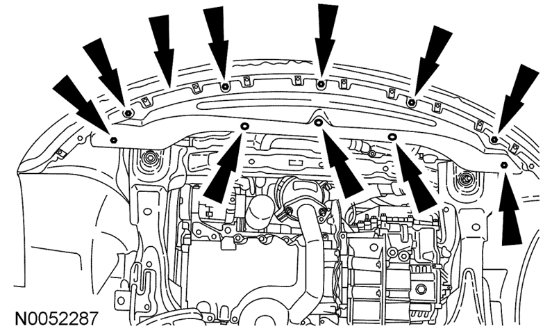
- Remove the 3 push-pins, the 7 screws and the radiator splash shield.
-
Place a suitable container below the radiator draincock.
- Open the draincock and allow to drain.
- Close the draincock after draining.
Filling and Bleeding without a Vacuum Cooling System Filler - 2.0L EcoBoost
NOTICE: Engine coolant provides boil protection, corrosion protection, freeze protection, and cooling efficiency to the engine and cooling components. In order to obtain these protections, maintain the engine coolant at the correct concentration and fluid level in the degas bottle.
To maintain the integrity of the coolant and the cooling system:
- Add Motorcraft® Orange Antifreeze/Coolant or equivalent. Do not mix coolant types.
- Do not add or mix with any other type of engine coolant. Mixing coolants may degrade the coolant's corrosion protection.
- Do not add alcohol, methanol, or brine, or any engine coolants mixed with alcohol or methanol antifreeze. These can cause engine damage from overheating or freezing.
- Ford Motor Company does NOT recommend the use of recycled engine coolant in vehicles originally equipped with Motorcraft® Orange Antifreeze/Coolant since a Ford-approved recycling process is not yet available.
NOTICE: Do not use stop-leak style pellets/products as an additive in this engine cooling system. The addition of stop-leak style pellets/products can clog or damage the cooling system resulting in degraded cooling system performance and/or failure.
- Install the radiator splash shield, the 7 screws and the 3 push-pins.
- Open the bleed valve on the heater core inlet hose.

-
NOTE: Make sure the coolant flows from the radiator through the upper radiator hose and fills the engine. When full, coolant should flow from the bleed hole.
When adding or topping off the engine coolant:- Measure the coolant concentration in the vehicle using Coolant/Battery Refractometer 300-ROB75240 or equivalent.
- Determine the concentration desired based on the vehicle duty cycle of extreme hot or cold operating conditions.
-
Add/top off or adjust the coolant as follows:
- For concentrations measured 48/52 to 50/50 (equates to a freeze point between -34°C (-30°F) and -37°C (-34°F)), use Motorcraft® Orange Antifreeze/Coolant Prediluted to maintain a coolant concentration in this same range.
- For all other concentrations, use Motorcraft® Orange Antifreeze/Coolant Concentrated and/or distilled water to get to the desired concentration.
- When refilling the engine coolant after a flush procedure, use a mixture of Motorcraft® Orange Antifreeze/Coolant Concentrated and distilled water to get to the desired concentration.
- Recommended coolant concentration is 48/52 to 50/50 (freeze protection -34°C (-30°F) and -37°C (-34°F)) engine coolant to distilled water.
-
For extremely cold climates (less than -37°C (-34°F):
- It may be necessary to increase the coolant concentration above 50%.
- NEVER increase the coolant concentration above 60%.
- Maximum coolant concentration is 60/40 for cold weather areas.
- A coolant concentration of 60% provides freeze point protection down to -50°C (-58°F).
- Engine coolant concentration above 60% will decrease the overheat protection characteristics of the engine coolant and may damage the engine.
-
For extremely hot climates:
- It is still necessary to maintain the coolant concentration above 40%.
- NEVER decrease the coolant concentration below 40%.
- Minimum coolant concentration is 40/60 for warm weather areas.
- A coolant concentration of 40% provides freeze point protection down to -34°C (-30°F).
- Engine coolant concentration below 40% will decrease the corrosion and freeze protection characteristics of the engine coolant and may damage the engine.
- Vehicles driven year-round in non-extreme climates should use a 48/52 to 50/50 (freeze protection -34°C (-30°F) and -37°C (-34°F)) mixture of engine coolant and distilled water for optimum cooling system and engine protection.
- Fill the degas bottle to 25 mm (0.984 in) above the COLD FILL line.
- Install the degas bottle cap and close the bleed valve.
- Turn the climate control system off.
- Start the engine and increase the engine speed to 3,500 rpm and hold for 30 seconds.
- Turn the engine off for and wait for 1 minute to purge any large air pockets from the cooling system.
-
Check the engine coolant level in degas bottle and if necessary fill to 25 mm (0.984 in) above the top of the COLD FILL LEVEL on the degas bottle if the engine is warm or to the top of the COLD FILL LEVEL if the engine is cold.WARNING: Always allow the engine to cool before opening the cooling system. Do not unscrew the coolant pressure relief cap when the engine is operating or the cooling system is hot. The cooling system is under pressure; steam and hot liquid can come out forcefully when the cap is loosened slightly. Failure to follow these instructions may result in serious personal injury.
- Start the engine and let it idle until the engine reaches normal operating temperature and the thermostat is fully open. A fully open thermostat is verified by the cooling fan cycling on at least once.
- Increase the engine speed to 3,500 rpm and hold for 30 seconds.
- Allow the engine to idle for 30 seconds.
- Turn the engine off for 1 minute.
- Repeat steps 9 through 11 a total of 5 times to remove any remaining air trapped in the system.
-
Check the engine coolant level in degas bottle and if necessary fill the degas bottle to the max level mark.WARNING: Always allow the engine to cool before opening the cooling system. Do not unscrew the coolant pressure relief cap when the engine is operating or the cooling system is hot. The cooling system is under pressure; steam and hot liquid can come out forcefully when the cap is loosened slightly. Failure to follow these instructions may result in serious personal injury.
- Install the degas bottle cap until at least 1 audible click is heard.
The full 2013 Edge-MKX Workshop Manual section, which includes the 3.5L/3.7L Duratec engine procedure, is attached below as a PDF document...
Good luck!
-
1
-
Placing your device cursor over underlined acronyms may yield popup full-words descriptions of the acronyms...
TECHNICAL SERVICE BULLETIN
No Audio/Sound And/Or Replacement DSP Will Not Program25-2275
23 June 2025Model:
Lincoln2024-2025 NautilusBuilt on or before 24-Mar-202524-Channel Audio Digital Signal Processing Module (DSP)Markets: North American markets only
Issue: Some of the vehicles listed in the Model statement above may exhibit no audio/sound and/or replacement DSP PMI that does not complete. This may be due to the software in the DSP.
Action: For vehicles that meet all of the criteria in the Issue and Model statements, follow the Service Procedure to reprogram or replace the DSP.
Parts
Service Part Number Claim Quantity Package Order Quantity Number in Package Description R2TZ-18B849-M Only If Necessary (Up To 1) Only If Necessary (Up To 1) 1 24-Channel Digital Audio Signal Processing Module (DSP) Service part numbers and "number in package" quantity may change after publication, thus also affecting the "package order quantity". Refer to the parts catalog for the latest information.
Claim Quantity refers to the total number of individual pieces required to repair the vehicle.
Package Order Quantity refers to the amount of the service part number package(s) required to repair the vehicle.
Number In Package refers to the number of individual pieces included in a service part number package.
Only If Necessary indicates the part is not mandatory. Refer to the Service Procedure to determine the inspection/inclusion criteria.
Warranty Status: Eligible under provisions of New Vehicle Limited Warranty (NVLW)/Service Part Warranty (SPW)/Service Part New Vehicle (SPNV)/Extended Service Plan (ESP) coverage. Limits/policies/prior approvals are not altered by a TSB. NVLW/SPW/SPNV/ESP coverage limits are determined by the identified causal part and verified using the OASIS part coverage tool.
Labor Times
Description Operation No. Time 2024-2025 Nautilus: Verify Feature Code, Software Level And Replace The DSP (Do Not Use With Any Other Labor Operations) 252275A 0.8 Hrs. 2024-2025 Nautilus: Verify Feature Code, Software Level Includes Time To Verify Module Communication, PMI Or Reprogram As Required (Do Not Use With Any Other Labor Operations) 252275B 0.4 Hrs. 2024-2025 Nautilus: Verify Feature Code, Software Level Includes Time To Verify Module Communication, Remove Inspect And Reinstall Fuse And PMI Or Reprogram As Required (Do Not Use With Any Other Labor Operations) 252274C 0.4 Hrs. Repair/Claim Coding
Causal Part: 18B849 Condition Code: 04 Service Procedure
1. Review the vehicle build information by double-clicking the VIN in the upper left corner in the PTS. Was the vehicle built with minor feature code IDBBN?
(1). Yes - proceed to Step 2.
(2). No - this article does not apply. For further diagnostics, refer to WSM, Section 415-00 > Diagnosis and Testing.
2. Review the vehicle software information by selecting the Diagnostics tab > Vehicle Software in PTS. Does the DSP currently show software part no. RC5T-14C589-BN or RC5T-14C589-BP?
(1). Yes - install a new DSP. Refer to WSM, Section 415-00 > Removal and Installation. Repair is complete.
(2). No - proceed to Step 3.
3. Using the latest version of the FDRS scan tool, perform a network test. Does the DSP communicate with the scan tool?
(1). Yes - proceed to Step 5.
(2). No - proceed to Step 4.
4. Remove the DSP fuse F138 from the BCMC, inspect the fuse for an open, and make sure the fuse has proper blade contact. After one minute, reinstall the good fuse. Does the DSP now communicate with the scan tool?
(1). Yes - proceed to Step 5.
(2). No - this article does not apply. Refer to WSM, Section 418-00A > Diagnosis and Testing.
5. Has the DSP previously been replaced?
(1). Yes - attempt PMI on the DSP again using the latest version of FDRS.
(2). No - reprogram the DSP using the latest version of FDRS.
© 2025 Ford Motor Company
All rights reserved.
NOTE: The information in Technical Service Bulletins is intended for use by trained, professional technicians with the knowledge, tools, and equipment to do the job properly and safely. It informs these technicians of conditions that may occur on some vehicles, or provides information that could assist in proper vehicle service. The procedures should not be performed by "do-it-yourselfers". Do not assume that a condition described affects your car or truck. Contact a Ford or Lincoln dealership to determine whether the Bulletin applies to your vehicle. Warranty Policy and Extended Service Plan documentation determine Warranty and/or Extended Service Plan coverage unless stated otherwise in the TSB article. The information in this Technical Service Bulletin (TSB) was current at the time of printing. Ford Motor Company reserves the right to supersede this information with updates. The most recent information is available through Ford Motor Company's on-line technical resources.
This Technical Service Bulletin is also attached below as a PDF document...
TSB 25-2275 - 2024-2025 Nautilus - No Audio-Sound And-Or Replacement DSP Will Not Program.pdf
-
2
-
-
@bogmanglen: The 2021 Edge Workshop Manual diagnostic Pinpoint Test AA directs to perform a Powertrain Control Module (PCM) Self Test scan-tool/Forscan procedure to see if any PCM DTC(s) are revealed.
PINPOINT TEST AA: U0401:00, U0401:82, U0422:68, U0422:81, U0452:82
If yes. report the PCM DTC(s) back here.
If no, then a symptom-based diagnostic Pinpoint Test L, which evaluates many potential contributing factors, will need to be employed.
Pinpoint Test L and several -- but not all -- of its supporting documents are attached below for you to assess, if you wish to personally pursue the solution or if you might choose to have a professional technician address it on your behalf.
Good luck!PINPOINT TEST L - THE A-C (AIR CONDITIONING) IS INOPERATIVE - NO DIAGNOSTIC TROUBLE CODES (DTCS) - 2021 Edge Workshop Manual.pdf Climate Control System - System Operation and Component Description - 2021 Edge Workshop Manual.pdf Refrigerant System Tests - 2.0L EcoBoost - General Procedures - 2021 Edge Workshop Manual.pdf
-
3
-
-
@Bunky: It is presently unclear what Ford Engineering's remedy will be.
The most recent listing of Components Requiring a Repair Validation Code (RVC), and the various authorities involved, is available here...
Good luck!
-
1
-
-
Components Requiring a Repair Validation Code (RVC) for Warranty* (updated 12-May-2025)
RVCs may be obtained using different methods as noted in this chart:
Pinpoint Test (PPT) or Guided Routine Manual RVC Form Dealer Software Support Hotline (DSSH)** PPT/DSSH ✓ ✓ DSSH ✓ PPT/Manual ✓ ✓ For VINs with the following outstanding Field Service Actions, RVCs may be obtained using the Manual RVC form.
Field Service Action Number Component 23C25 IPC 25C02 IPC ** IMPORTANT information about using the DSSH:
- Use the PTS Diagnostics and Workshop tabs to determine the correct test or routine for the vehicle concern.
- DSSH is provided only when diagnostics direct a component replacement.
- Do not remove the component prior to submitting a Technical Support Request (TSR) to the DSSH.
* The charts below are general guidelines for vehicles and components requiring an RVC for warranty claims. Specific vehicle base or extended warranty coverage must be confirmed using the warranty start date or mileage. Country or state regulations can affect warranty periods for emission-related components.
2025 Model Year Vehicle SYNC Accessory Protocol Interface Module
(APIM)
14D212 / 14G371 / 14H522Display Screen Equipped with
SYNC
10D885Image Processing Module A
(IPMA)
14G647 / 19H406Image Processing Module B
(IPMB)
19H405Powertrain Control Module
(PCM)
12A650Power Steering Control Module
(PSCM)
3504Body Control Module
(BCM)
15604Gateway Module
(GWM)
14G490Telematics Control Unit Module
(TCU)
14F546 / 14G229Instrument Panel Cluster
(IPC)
108492025 Aviator PPT/DSSH PPT/Manual DSSH PPT/DSSH DSSH DSSH DSSH DSSH 2025 Bronco PPT/DSSH PPT/Manual DSSH DSSH PPT/DSSH PPT/Manual DSSH DSSH DSSH DSSH 2025 Bronco Sport PPT/DSSH PPT/Manual DSSH PPT/DSSH PPT/Manual DSSH DSSH DSSH DSSH 2025 Corsair PPT/DSSH PPT/Manual DSSH PPT/DSSH DSSH DSSH DSSH DSSH 2025 E-350/450 PPT/DSSH PPT/Manual PPT/DSSH DSSH DSSH 2025 Escape PPT/DSSH PPT/Manual DSSH PPT/DSSH DSSH DSSH DSSH DSSH 2025 Expedition PPT/DSSH PPT/Manual DSSH PPT/DSSH DSSH DSSH DSSH DSSH 2025 Explorer PPT/DSSH PPT/Manual DSSH DSSH PPT/DSSH DSSH DSSH DSSH DSSH 2025 F-150 PPT/DSSH PPT/Manual DSSH PPT/DSSH PPT/Manual DSSH DSSH DSSH DSSH 2025 F-250-600 Super Duty PPT/DSSH PPT/Manual DSSH PPT/DSSH PPT/Manual DSSH DSSH DSSH DSSH 2025 F-53 Motorhome/F-59 Strip Chassis PPT/DSSH DSSH 2025 F-650/750 PPT/DSSH PPT/Manual PPT/DSSH DSSH DSSH 2025 Maverick PPT/DSSH PPT/Manual DSSH PPT/DSSH PPT/Manual DSSH DSSH DSSH DSSH 2025 Mustang PPT/DSSH PPT/Manual DSSH DSSH PPT/DSSH DSSH DSSH DSSH DSSH 2025 Mustang Mach-E PPT/DSSH PPT/Manual DSSH DSSH PPT/DSSH PPT/Manual DSSH DSSH DSSH DSSH 2025 Nautilus PPT/DSSH PPT/Manual DSSH PPT/DSSH DSSH DSSH DSSH DSSH 2025 Navigator PPT/DSSH PPT/Manual DSSH PPT/DSSH DSSH DSSH DSSH DSSH 2025 Ranger PPT/DSSH PPT/Manual DSSH PPT/DSSH DSSH DSSH DSSH DSSH 2025 Transit PPT/DSSH PPT/Manual DSSH PPT/DSSH PPT/Manual DSSH DSSH DSSH DSSH
2024 Model Year Vehicle SYNC Accessory Protocol Interface Module
(APIM)
14D212 / 14G371 / 14H522Display Screen Equipped with
SYNC
10D885Image Processing Module A
(IPMA)
14G647 / 19H406Image Processing Module B
(IPMB)
19H405Powertrain Control Module
(PCM)
12A650Power Steering Control Module
(PSCM)
3504Body Control Module
(BCM)
15604Gateway Module
(GWM)
14G490Telematics Control Unit Module
(TCU)
14F546 / 14G229Instrument Panel Cluster
(IPC)
108492024 Aviator PPT/DSSH PPT/Manual DSSH DSSH PPT/DSSH DSSH DSSH 2024 Bronco PPT/DSSH PPT/Manual DSSH DSSH PPT/DSSH PPT/Manual DSSH DSSH DSSH DSSH 2024 Bronco Sport PPT/DSSH PPT/Manual DSSH DSSH PPT/DSSH PPT/Manual DSSH DSSH 2024 Corsair PPT/DSSH PPT/Manual DSSH PPT/DSSH DSSH DSSH DSSH DSSH 2024 E-350/450 PPT/DSSH PPT/Manual DSSH PPT/DSSH DSSH DSSH 2024 Edge PPT/DSSH PPT/Manual DSSH DSSH PPT/DSSH DSSH DSSH DSSH DSSH 2024 Escape PPT/DSSH PPT/Manual DSSH PPT/DSSH DSSH DSSH DSSH DSSH 2024 Expedition PPT/DSSH PPT/Manual DSSH PPT/DSSH DSSH DSSH DSSH DSSH 2024 Explorer PPT/DSSH PPT/Manual DSSH DSSH PPT/DSSH DSSH DSSH 2024 F-150 PPT/DSSH PPT/Manual DSSH PPT/DSSH PPT/Manual DSSH DSSH DSSH DSSH 2024 F-250-600 Super Duty PPT/DSSH PPT/Manual DSSH PPT/DSSH PPT/Manual DSSH DSSH DSSH DSSH 2024 F-53 Motorhome/F-59 Strip Chassis DSSH PPT/DSSH DSSH 2024 F-650/750 PPT/DSSH PPT/Manual DSSH PPT/DSSH DSSH DSSH 2024 Maverick PPT/DSSH PPT/Manual DSSH PPT/DSSH PPT/Manual DSSH DSSH 2024 Mustang PPT/DSSH PPT/Manual DSSH DSSH PPT/DSSH DSSH DSSH DSSH DSSH 2024 Mustang Mach-E PPT/DSSH PPT/Manual DSSH DSSH PPT/DSSH PPT/Manual DSSH DSSH DSSH DSSH 2024 Nautilus PPT/DSSH PPT/Manual DSSH PPT/DSSH DSSH DSSH DSSH DSSH 2024 Navigator PPT/DSSH PPT/Manual DSSH PPT/DSSH DSSH DSSH DSSH DSSH 2024 Ranger PPT/DSSH PPT/Manual DSSH PPT/DSSH DSSH DSSH DSSH DSSH 2024 Transit PPT/DSSH PPT/Manual DSSH DSSH PPT/DSSH PPT/Manual DSSH DSSH DSSH DSSH
2023 Model Year Vehicle SYNC Accessory Protocol Interface Module
(APIM)
14D212 / 14G371 / 14H522Display Screen Equipped with
SYNC
10D885Image Processing Module A
(IPMA)
14G647 / 19H406Image Processing Module B
(IPMB)
19H405Powertrain Control Module
(PCM)
12A650Power Steering Control Module
(PSCM)
3504Body Control Module
(BCM)
15604Gateway Module
(GWM)
14G490Telematics Control Unit Module
(TCU)
14F546 / 14G229Instrument Panel Cluster
(IPC)
108492023 Aviator PPT/DSSH PPT/Manual DSSH DSSH PPT/DSSH DSSH DSSH 2023 Bronco PPT/DSSH PPT/Manual DSSH DSSH PPT/DSSH PPT/Manual DSSH DSSH DSSH DSSH 2023 Bronco Sport PPT/DSSH PPT/Manual DSSH DSSH PPT/DSSH PPT/Manual DSSH DSSH 2023 Corsair PPT/DSSH PPT/Manual DSSH PPT/DSSH DSSH DSSH DSSH DSSH 2023 E-350/450 PPT/DSSH PPT/Manual DSSH PPT/DSSH DSSH DSSH 2023 Edge PPT/DSSH PPT/Manual DSSH DSSH PPT/DSSH DSSH DSSH DSSH DSSH 2023 Escape PPT/DSSH PPT/Manual DSSH PPT/DSSH DSSH DSSH DSSH DSSH 2023 Expedition PPT/DSSH PPT/Manual DSSH PPT/DSSH DSSH DSSH DSSH DSSH 2023 Explorer PPT/DSSH PPT/Manual DSSH DSSH PPT/DSSH DSSH DSSH 2023 F-150 PPT/DSSH PPT/Manual DSSH PPT/DSSH PPT/Manual DSSH DSSH DSSH DSSH 2023 F-250-600 Super Duty PPT/DSSH PPT/Manual DSSH PPT/DSSH PPT/Manual DSSH DSSH DSSH DSSH 2023 F-53 Motorhome/F-59 Strip Chassis DSSH PPT/DSSH DSSH 2023 F-650/750 PPT/DSSH PPT/Manual DSSH PPT/DSSH DSSH DSSH 2023 Maverick PPT/DSSH PPT/Manual DSSH PPT/DSSH PPT/Manual DSSH DSSH 2023 Mustang PPT/DSSH PPT/Manual DSSH PPT/DSSH DSSH DSSH 2023 Mustang Mach-E PPT/DSSH PPT/Manual DSSH DSSH PPT/DSSH PPT/Manual DSSH DSSH DSSH DSSH 2023 Nautilus PPT/DSSH PPT/Manual DSSH DSSH PPT/DSSH DSSH DSSH DSSH DSSH 2023 Navigator PPT/DSSH PPT/Manual DSSH PPT/DSSH DSSH DSSH DSSH DSSH 2023 Ranger PPT/DSSH PPT/Manual DSSH PPT/DSSH DSSH DSSH 2023 Transit PPT/DSSH PPT/Manual DSSH DSSH PPT/DSSH PPT/Manual DSSH DSSH DSSH DSSH 2023 Transit Connect PPT/DSSH PPT/Manual DSSH PPT/DSSH DSSH DSSH
2022 Model Year Vehicle SYNC Accessory Protocol Interface Module
(APIM)
14D212 / 14G371 / 14H522Display Screen Equipped with
SYNC
10D885Image Processing Module A
(IPMA)
14G647 / 19H406Image Processing Module B
(IPMB)
19H405Powertrain Control Module
(PCM)
12A650Power Steering Control Module
(PSCM)
3504Gateway Module
(GWM)
14G490Telematics Control Unit Module
(TCU)
14F546 / 14G2292022 Aviator PPT/DSSH PPT/Manual DSSH DSSH PPT/Manual 2022 Bronco PPT/DSSH PPT/Manual DSSH DSSH PPT/Manual PPT/Manual PPT/Manual PPT/Manual 2022 Bronco Sport PPT/DSSH PPT/Manual DSSH DSSH PPT/Manual PPT/Manual 2022 Corsair PPT/DSSH PPT/Manual DSSH DSSH PPT/Manual 2022 E-350/450 PPT/DSSH PPT/Manual DSSH PPT/Manual 2022 EcoSport PPT/DSSH PPT/Manual PPT/Manual 2022 Edge PPT/DSSH PPT/Manual DSSH DSSH PPT/Manual PPT/Manual PPT/Manual 2022 Escape PPT/DSSH PPT/Manual DSSH DSSH PPT/Manual 2022 Expedition PPT/DSSH PPT/Manual DSSH PPT/Manual PPT/Manual PPT/Manual 2022 Explorer PPT/DSSH PPT/Manual DSSH DSSH PPT/Manual 2022 F-150 PPT/DSSH PPT/Manual DSSH PPT/Manual PPT/Manual PPT/Manual PPT/Manual 2022 F-250-600 Super Duty PPT/DSSH PPT/Manual DSSH DSSH PPT/Manual PPT/Manual PPT/Manual 2022 F-53 Motorhome/F-59 Strip Chassis DSSH PPT/Manual 2022 F-650/750 PPT/DSSH PPT/Manual DSSH PPT/Manual 2022 Maverick PPT/DSSH PPT/Manual DSSH PPT/Manual PPT/Manual 2022 Mustang PPT/DSSH PPT/Manual DSSH PPT/Manual 2022 Mustang Mach-E PPT/DSSH PPT/Manual DSSH DSSH PPT/Manual PPT/Manual PPT/Manual PPT/Manual 2022 Nautilus PPT/DSSH PPT/Manual DSSH DSSH PPT/Manual PPT/Manual PPT/Manual 2022 Navigator PPT/DSSH PPT/Manual DSSH PPT/Manual PPT/Manual PPT/Manual 2022 Ranger PPT/DSSH PPT/Manual DSSH PPT/Manual 2022 Transit PPT/DSSH PPT/Manual DSSH DSSH PPT/Manual PPT/Manual PPT/Manual PPT/Manual 2022 Transit Connect PPT/DSSH PPT/Manual DSSH PPT/Manual
2021 Model Year Vehicle SYNC Accessory Protocol Interface Module
(APIM)
14D212 / 14G371 / 14H522Display Screen Equipped with
SYNC
10D885Powertrain Control Module
(PCM)
12A650Power Steering Control Module
(PSCM)
3504Gateway Module
(GWM)
14G490Telematics Control Unit Module
(TCU)
14F546 / 14G2292021 Aviator PPT/DSSH PPT/Manual PPT/Manual 2021 Bronco PPT/DSSH PPT/Manual PPT/Manual PPT/Manual PPT/Manual PPT/Manual 2021 Bronco Sport PPT/DSSH PPT/Manual PPT/Manual PPT/Manual 2021 Corsair PPT/DSSH PPT/Manual PPT/Manual 2021 E-350/450 PPT/DSSH PPT/Manual PPT/Manual 2021 EcoSport PPT/DSSH PPT/Manual PPT/Manual 2021 Edge PPT/DSSH PPT/Manual PPT/Manual PPT/Manual PPT/Manual 2021 Escape PPT/DSSH PPT/Manual PPT/Manual 2021 Expedition PPT/DSSH PPT/Manual PPT/Manual 2021 Explorer PPT/DSSH PPT/Manual PPT/Manual 2021 F-150 PPT/DSSH PPT/Manual PPT/Manual PPT/Manual PPT/Manual PPT/Manual 2021 F-250-600 Super Duty PPT/DSSH PPT/Manual PPT/Manual 2021 F-53 Motorhome/F-59 Strip Chassis PPT/Manual 2021 F-650/750 PPT/DSSH PPT/Manual PPT/Manual 2021 Mustang PPT/DSSH PPT/Manual PPT/Manual 2021 Mustang Mach-E PPT/DSSH PPT/Manual PPT/Manual PPT/Manual PPT/Manual PPT/Manual 2021 Nautilus PPT/DSSH PPT/Manual PPT/Manual PPT/Manual PPT/Manual 2021 Navigator PPT/DSSH PPT/Manual PPT/Manual 2021 Ranger PPT/DSSH PPT/Manual PPT/Manual 2021 Transit PPT/DSSH PPT/Manual PPT/Manual PPT/Manual 2021 Transit Connect PPT/DSSH PPT/Manual PPT/Manual
2020 Model Year Vehicle SYNC Accessory Protocol Interface Module
(APIM)
14D212 / 14G371 / 14H522Display Screen Equipped with
SYNC
10D885Powertrain Control Module
(PCM)
12A650Power Steering Control Module
(PSCM)
3504Body Control Module
(BCM)
15604Electric Brake Booster
(EBB)
2005Steering Effort Control Module
(SECM)
3600Anti-Lock Brake Module (ABS)
Hydraulic Control Unit (HCU)
2C219 / 2C215 / 2B373 / 2C405 / 2C286 / 2B513Heating, Ventilation and Air Conditioning Module
(HVAC)
19980Front Controls Interface Module
(FCIM)
18842Instrument Panel Cluster
(IPC)
10849Glow Plug Control Module
(GPCM)
12B5332020 Aviator PPT/Manual PPT/Manual PPT/Manual PPT/Manual PPT/Manual PPT/Manual 2020 Continental PPT/Manual PPT/Manual PPT/Manual PPT/Manual PPT/Manual PPT/Manual PPT/Manual PPT/Manual 2020 Corsair PPT/Manual PPT/Manual PPT/Manual PPT/Manual PPT/Manual PPT/Manual PPT/Manual 2020 EcoSport PPT/Manual PPT/Manual PPT/Manual PPT/Manual PPT/Manual 2020 Edge PPT/Manual PPT/Manual PPT/Manual PPT/Manual PPT/Manual PPT/Manual PPT/Manual PPT/Manual 2020 Escape PPT/Manual PPT/Manual PPT/Manual PPT/Manual PPT/Manual PPT/Manual PPT/Manual 2020 Expedition PPT/Manual PPT/Manual PPT/Manual PPT/Manual PPT/Manual PPT/Manual 2020 Explorer PPT/Manual PPT/Manual PPT/Manual PPT/Manual PPT/Manual PPT/Manual PPT/Manual 2020 F-150 PPT/Manual PPT/Manual PPT/Manual PPT/Manual PPT/Manual PPT/Manual PPT/Manual PPT/Manual PPT/Manual 2020 F-250-600 Super Duty PPT/Manual PPT/Manual PPT/Manual PPT/Manual PPT/Manual PPT/Manual PPT/Manual PPT/Manual PPT/Manual 2020 F-53 Motorhome/F-59 Strip Chassis PPT/Manual PPT/Manual 2020 Fusion PPT/Manual PPT/Manual PPT/Manual PPT/Manual PPT/Manual PPT/Manual PPT/Manual PPT/Manual 2020 MKZ PPT/Manual PPT/Manual PPT/Manual PPT/Manual PPT/Manual PPT/Manual PPT/Manual PPT/Manual 2020 Mustang PPT/Manual PPT/Manual PPT/Manual PPT/Manual PPT/Manual PPT/Manual PPT/Manual PPT/Manual 2020 Nautilus PPT/Manual PPT/Manual PPT/Manual PPT/Manual PPT/Manual PPT/Manual PPT/Manual PPT/Manual 2020 Navigator PPT/Manual PPT/Manual PPT/Manual PPT/Manual PPT/Manual PPT/Manual 2020 Ranger PPT/Manual PPT/Manual PPT/Manual PPT/Manual PPT/Manual PPT/Manual 2020 Transit PPT/Manual PPT/Manual PPT/Manual PPT/Manual PPT/Manual PPT/Manual PPT/Manual 2020 Transit Connect PPT/Manual PPT/Manual PPT/Manual PPT/Manual PPT/Manual PPT/Manual
2019 Model Year Vehicle Powertrain Control Module
(PCM)
12A6502019 Continental PPT/Manual 2019 E-350/450 PPT/Manual 2019 EcoSport PPT/Manual 2019 Edge PPT/Manual 2019 Escape PPT/Manual 2019 Expedition PPT/Manual 2019 Explorer PPT/Manual 2019 F-150 PPT/Manual 2019 F-250-550 Super Duty PPT/Manual 2019 F-53 Motorhome/F-59 Strip Chassis PPT/Manual 2019 Fiesta PPT/Manual 2019 Flex PPT/Manual 2019 Fusion PPT/Manual 2019 MKC PPT/Manual 2019 MKT PPT/Manual 2019 MKZ PPT/Manual 2019 Mustang PPT/Manual 2019 Nautilus PPT/Manual 2019 Navigator PPT/Manual 2019 Ranger PPT/Manual 2019 Taurus PPT/Manual 2019 Transit PPT/Manual 2019 Transit Connect PPT/Manual
2018 Model Year Vehicle Powertrain Control Module
(PCM)
12A6502018 C-MAX Hybrid PPT/Manual 2018 Continental PPT/Manual 2018 E-350/450 2018 EcoSport PPT/Manual 2018 Edge PPT/Manual 2018 Escape PPT/Manual 2018 Expedition PPT/Manual 2018 Explorer PPT/Manual 2018 F-250-550 Super Duty 2018 F-53 Motorhome/F-59 Strip Chassis 2018 Fiesta PPT/Manual 2018 Flex PPT/Manual 2018 Focus PPT/Manual 2018 Focus RS PPT/Manual 2018 Fusion PPT/Manual 2018 MKC PPT/Manual 2018 MKT PPT/Manual 2018 MKX PPT/Manual 2018 MKZ PPT/Manual 2018 Mustang PPT/Manual 2018 Navigator PPT/Manual 2018 Taurus PPT/Manual 2018 Transit PPT/Manual 2018 Transit Connect PPT/Manual -
1
-
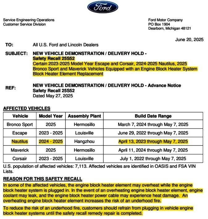
Ford has issued the Full U.S. Dealer Bulletin for Safety Recall 25S52, affecting eleven (11) U.S. Nautilus vehicles.Ford of Canada has not yet released their Full Dealer Bulletin, affecting many more Canadian-market Nautilus vehicles, but it will be added here once it's released.*** The following Dealer Bulletin has been edited to provide the information most relevant to Forum members. ***
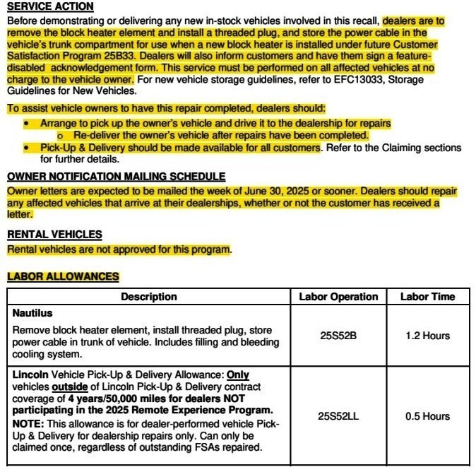 The Technical Instructions, which provide the service procedure to dealership technicians, and a Vehicle Feature Customer Acknowledgement form, which must be signed by the vehicle owner, are attached below as PDF documents...
Safety Recall 25S52 - Technical Instructions.pdf Safety Recall 25S52 - Vehicle Feature Customer Acknowledgement.pdf
-
While providing no additional information, Ford has elevated its earlier PTS Alert notification to a Special Service Message, a level of communication which is submitted to the National Highway Transportation Safety Administration (NHTSA), which eventually posts such messages to its website.
The broadly-described population of potentially affected vehicles, and the indication that this will-not-update condition is the direct result of Ford Engineering de-activating the vehicles' APIMs from performing normal updates, are especially noteworthy -- as is Ford urgency in preceding the SSM with its PTS Alert.
This post will be updated when additional information and/or actions are announced by Ford.
SSM 53966 - 2021-2025 Various Vehicles - SYNC4 - General System Performance And Stability - Programming No Longer Available Some 2021-2025 Ford/ Lincoln vehicles equipped with SYNC4 may not be able to perform an update to the accessory protocol interface module (APIM). This may be due to the software in the APIM. Ford Engineering has de-activated the ability to update these SYNC4 APIM modules as applicable, and the Ford Diagnosis and Repair System (FDRS) will not present an update for the APIM module. Some existing directed repairs may be impacted, check Professional Technician System (PTS) before attempting any specific technical service bulletin (TSB)/special service message (SSM) and check field service action (FSA) landing pages before attempting any FSA repairs. For any vehicle repairs requiring a software update that includes an APIM update in the programming sequence, if the 5-digit product code for the APIM software is equal to or lower than 23187, do not attempt to update affected modules at this time. To determine the 5-digit product code for the APIM software on the vehicle, while the vehicle center display screen is powered up with ignition in run or accessory, go to Settings > General > About SYNC. Find the 5-digit code (example: “SYNC 4, Software Version: 23187_PRODUCT”). If further support is required, follow normal internal dealer escalation process. -
1
-
-
Welcome to the Forum, James. Very sorry to learn about your wife's illness and treatment, which undoubtably provide significant challenges to you both.
Ford's Customer Relationship Center, (800) 392-3673, is staffed Monday through Friday, from 8am to 8pm with representatives to assist customers who are not able to gain satisfaction after discussing their vehicle issue(s) with the Sales Manager and Service Manager at the dealership level.
You mention discussing your 2024 Edge's unacceptable odor issue with the dealership General Manager and the Sales Manager, but you do not mention any Service Manager involvement, or if a dealership technician was assigned to investigate potential sources of the odor and found no special cause.
Ford's dealership locator shows several other Ford dealers within 10-20 miles from Draper UT (link to Ford search results).
Given the unyielding response at your Edge's selling dealer, it may be prudent for you to take your Edge to a different dealership -- or two, for a second -- or third, professional opinion about if the Objectionable Odor, in your view, is judged as being New Car Smell in their view. Perhaps another dealer will be responsive to your concern, especially given your wife's reaction to the Edge's smell.
I am honestly surprised that the selling dealership was unwilling to sublet deodorizing your Edge to a third-party detailer -- if even at their own expense -- to preserve your satisfaction with their involvement.
If your consultation with another dealer brings no improvement, perhaps the Customer Relationship Center will authorize the selling dealer to have a third-party specialist attempt improvement under your Edge's Bumper-to-Bumper warranty.
The 2022-2024 Edge Workshop Manual provides the following guidance toward dealing with odorous vehicle conditions...
The complete Workshop Manual procedure includes cleansing the A/C cooling coils with special equipment, and two resources are attached below as PDF documents.
Good luck!
Air Conditioning (A/C) Odor Treatment Inspection
NOTE: There are typically 4 types of objectionable odors found in a vehicle:
Before determining that A/C odor treatment is required, determine the source and the circumstances under which the odor occurs.
NOTE: Chemical odors are usually constant regardless of the climate control system setting although they may be enhanced by A/C operation. Most chemical odors are caused by fluid leaks or incorrectly cured adhesives. Chemical odors can be eliminated by repairing the leaking component and removing any residue.
NOTE: Environmental odors usually occur for a short time and diminish after the vehicle passes through the affected area. These odors are typically only detected when the vehicle windows are open, or when the climate control system is operating in a mode that allows for fresh air. Environmental odors cannot be eliminated because they are external in source, but they may be minimized by switching to a climate control setting that uses recirculated air.
NOTE: Human and other interior-generated odors occur while the source is present and may linger for a short time after. These odors may be more noticeable during A/C operation. Human odors may be eliminated by removing the source and cleaning the affected area.
NOTE: Microbiological odors, if in the A/C system, usually last for about 30 seconds after the system is turned on. They are detected while the A/C is turned on and using either outside or recirculated air. Microbiological odors that occur in areas other than the A/C system (for example, water in doors or wet carpeting) may last indefinitely and are more intense when recirculated air is used. Microbiological odors are not present at temperatures at or below 10°C (50°F).
Microbiological odors can be eliminated by removing the source and treating the affected area. Allow standing water to drain and dry out. A/C systems may be treated by using Motorcraft® A/C Cooling Coil Coating (YN-29) as described in the service procedure below.
NOTE: Microbiological odors result from microbial growth supported by warm temperatures and moisture. Microbiological odors are described as musty/mildew type smells and may occur on/in:
-
- Chemical odors
- Environmental odors
- Human and other interior-generated odors
- Microbiological odors
Repair
-
- Foam seals
- Rubber seals
- Adhesives
- Standing water
- Water soaked carpet/trim
-
Identify the type of odor present in the vehicle. Do not proceed with A/C odor treatment if the odor source is found to be outside of the A/C system. Refer to the following list for examples.
Odor Source Odor Description Chemical Odors Coolant Sweet smell Fuel Gasoline or diesel fuel smell Oil Oil type or burning smell Power Steering Fluid Oil type or burning smell Transmission Fluid Oil type or burning smell Washer Fluid Alcohol type smell Gear Lube Garlic/sulfur smell Refrigerant Oil Ether type smell Carpet/trim Adhesives Fishy, urine or sweet smell Evaporator Core Coating Wet cement type smell Environmental Odors Exhaust Exhaust, fuel or burning type smell Industrial Pollutants Various smells Dust Musty, mildew or wet cement type smell Pollen Sweet smell Tobacco Burning, tar smell Human and Other Interior Generated Odors Body Secretions Body odor Perfuming Agents Sweet or fragrance smell Clothing Musty, mildew or body odors Food/Beverage Sweet, musty, mildew or fishy smell Microbiological Odors Microbiological Odors Occurring Inside of A/C System Musty, mildew smell lasting about 30 seconds after A/C is turned on Microbiological Odors Occurring Outside of A/C System Musty, mildew smell lasting indefinitely and possibly more pronounced when using recirculated air
-
NOTE: Identify the source of the odor.
- Check the evaporator core drain tube for restriction.
- Check the passenger and driver side carpet for moisture. If moisture is found, A/C odor treatment is not necessary. Diagnose for a water leak as needed.
- Check the cabin air filter and cabin air filter cover for moisture resulting from water bypassing the cowl baffling system. If moisture is found, A/C odor treatment is not necessary. Diagnose for a water leak as needed.
- Check the inner cowl drain area and air inlet screen for material obstruction or standing water. Inspect the area removing any standing water and cleaning the air inlet screen if possible, by using a wet/dry vacuum.
Air Conditioning (A-C) Odor Treatment - General Procedures - 2022-2024 Edge Workshop Manual.pdf AirSept - YN-29 Applicator (258-62644).pdf
-
2
-
-
On June 20, 2025, Ford provided the following information to dealership Service personnel via an Alert issued on the Professional Technician System (PTS) website...
Some 2021-2024 Ford and Lincoln vehicles equipped with SYNC 4 may not be able to perform an update to the accessory protocol interface module (APIM).
This may be due to the software in the APIM. Ford Engineering has de-activated the ability to update these SYNC 4 APIM modules and as applicable, the Ford Diagnosis and Repair System (FDRS) will not present an update for the APIM module. Some existing directed repairs may be impacted, check OASIS before attempting any specific TSB repairs and landing pages before attempting any specific FSA repairs. For any vehicles repairs requiring a software update that includes an APIM update in the programming sequence, if the 5-digit product code for the APIM software is equal to or lower than 23187, do not attempt to update affected modules at this time. To determine the 5-digit product code for the APIM software on the vehicle, while the vehicle center display screen is powered up with ignition in run or accessory, go to General Settings > Select About SYNC. Find the 5-digit code, example “ SYNC 4, Software Version: 23187_PRODUCT”.
This post will be updated when Ford offers fuller clarity, or, when a remedy is provided by Ford Engineering.
-
3
-
-
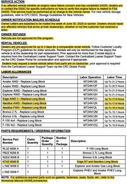
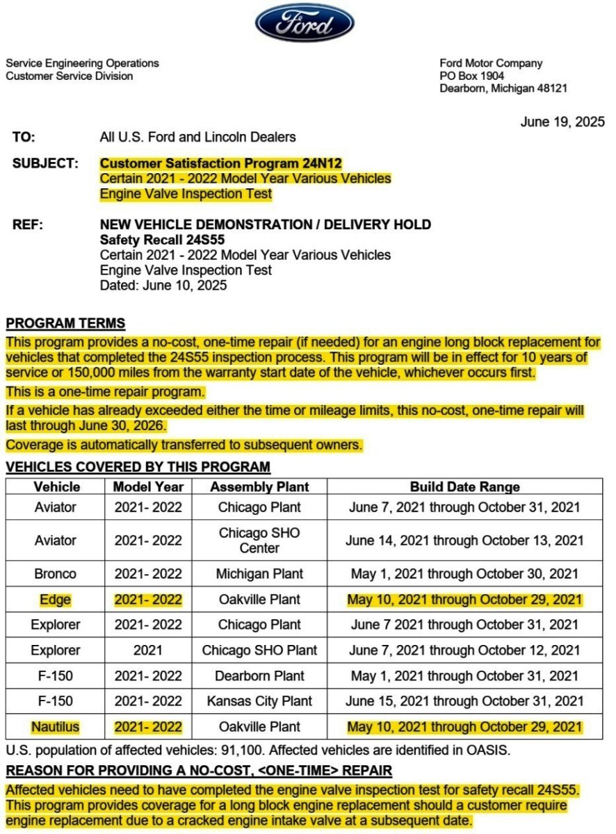
For affected vehicles that pass the engine valve inspection provided by Safety Recall 24S55, Ford is providing coverage for a long block engine replacement should the vehicle require engine replacement due to a cracked engine intake valve at a subsequent date, within 10 years/150,000 miles from vehicle's Warranty Start Date, or, if a vehicle has already exceeded either the time or mileage limits, this no-cost, one-time repair will last through June 30, 2026.
For more information, see...
-
2
-
-
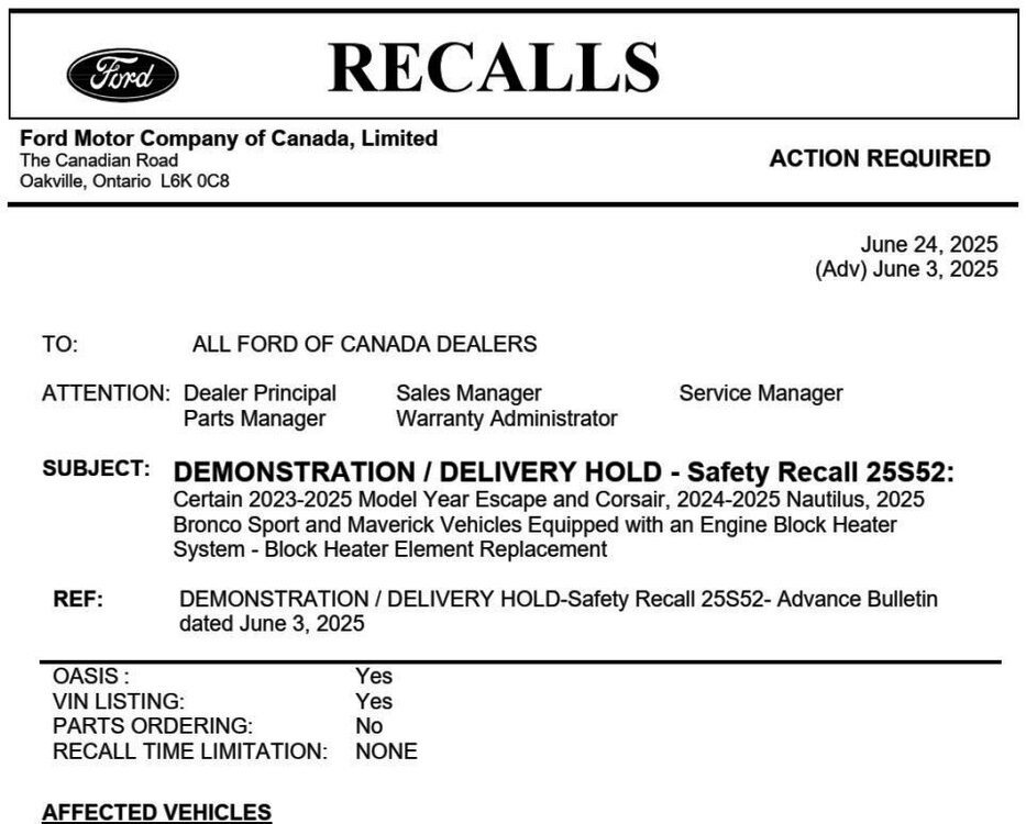
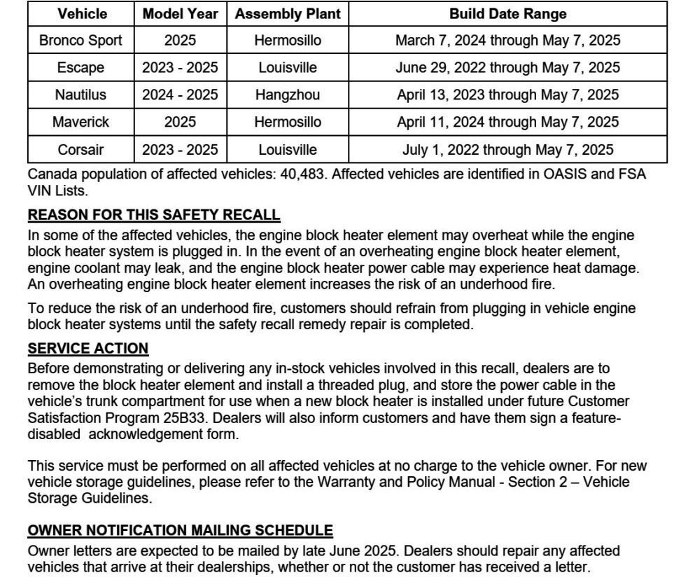
*** The following Dealer Bulletin has been edited to provide the information most relevant to Forum members. ***

-
3
-
-
From the above-quoted NHTSA Chronology Report, with emphasis added...
On January 25, 2022, Global CCRG opened an investigation into 2021 Model Year (MY) Lincoln Aviator and Nautilus vehicles equipped with 2.7L and 3.0L Nano EcoBoost gasoline engines after an international investigation discovered twenty-two (22) instances of engine failure at three (3) months in service or less. A review of failed engines revealed that the engine intake valves fractured and fell into the combustion chamber of the engine causing catastrophic engine damage leading to a Loss of Motive Power (LOMP). Based on an analysis of returned fractured valves from failed engines, Ford identified that the potential root cause of the failures was engine intake valve failure due to valves that exceeded the designed specification for hardness, were brittle, and more likely to fracture. Ford determined that this was due to the supplier’s grinding processes and the sensitivity of the intake valve material to grinding processes that were not within control specifications. The intake valve material was changed for vehicles produced after October 31, 2021. The new material increased the valve’s robustness to keeper groove grinding processes outside of control specifications.
Good luck!
-
3
-
-
Welcome to the Forum @Edgernnr!
From the Ford Powertrain Control/Emissions Diagnosis (PC/ED) Manual...
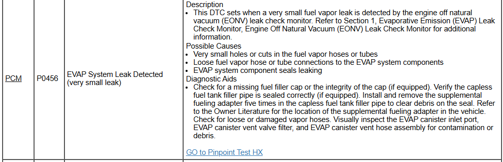
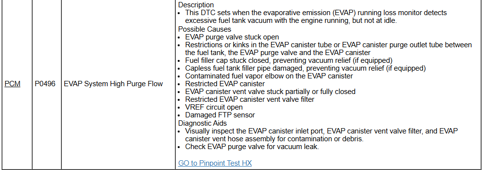
PC/ED Diagnostic Pinpoint Tests, and, Workshop Manual Evaporative Emissions component procedures, are attached below as PDF documents...
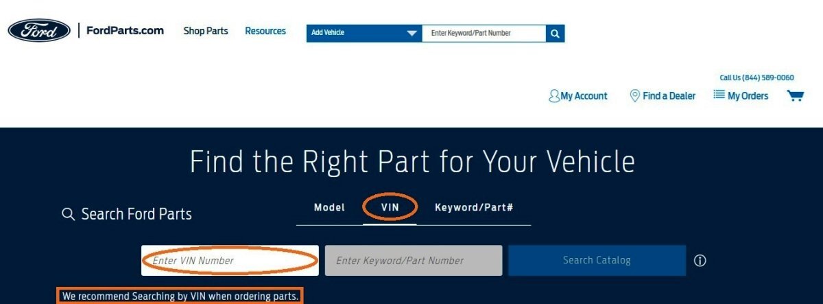
Inputting your Edge's VIN at the beginning of your FordParts part search should yield the correct part and/or indicate the part is not correct for the specified VIN...

Good luck!
PINPOINT TEST Z - INTERMITTENT - PC-ED Manual 2020 Gasoline.pdf PINPOINT TEST HX - EVAPORATIVE EMISSION (EVAP) SYSTEM AND MONITOR - PC-ED Manual 2020 Gasoline.pdf Evaporative Emissions - Overview - Description and Operation - 2020 Edge Workshop Manual.pdf Evaporative Emission System Leak Test - General Procedures - 2020 Edge Workshop Manual.pdf Evaporative Emission Blocking Valve - Removal and Installation - 2020 Edge Workshop Manual.pdf Evaporative Emission Canister - Removal and Installation - 2020 Edge Workshop Manual.pdf Evaporative Emission Canister Purge Valve - Removal and Installation - 2020 Edge Workshop Manual.pdf Evaporative Emission Canister Ventilation Filter - Removal and Installation - 2020 Edge Workshop Manual.pdf Evaporative Emission Canister Vent Solenoid - Removal and Installation - 2020 Edge Workshop Manual.pdf Fuel Tank Pressure Sensor and Tube - Removal and Installation - 2020 Edge Workshop Manual.pdf
-
2
-
1
-
-
Welcome to the Forum @JMB!
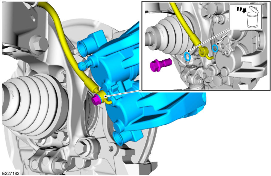
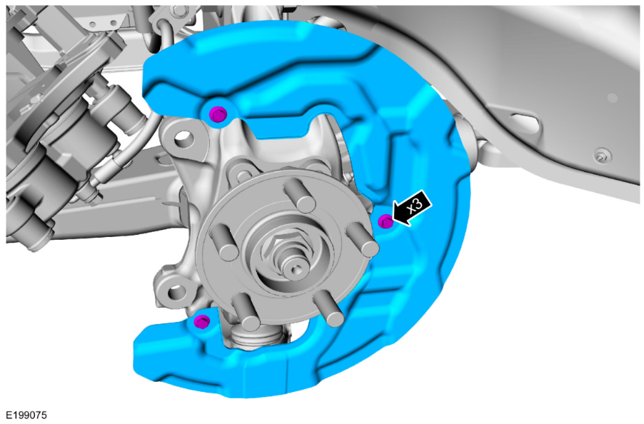
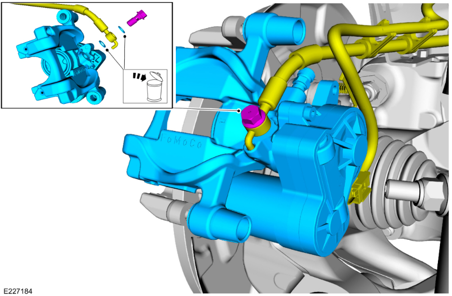
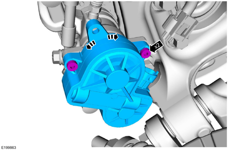
From the 2017 Edge Workshop Manual...
Front Brake Caliper Flow Bolt torque: 18 lb.ft (25 Nm)
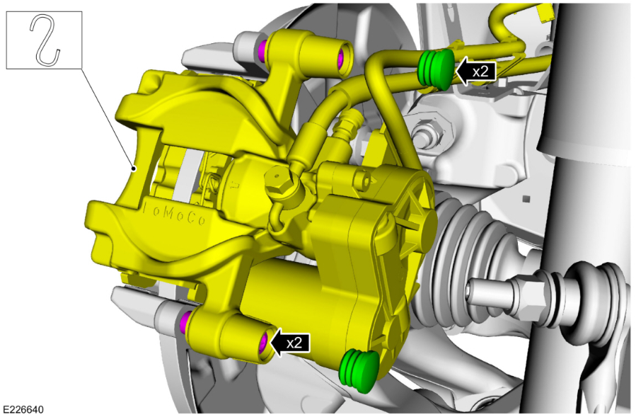
Front Brake Caliper Guide Pin torque: 41 lb.ft (55 Nm)
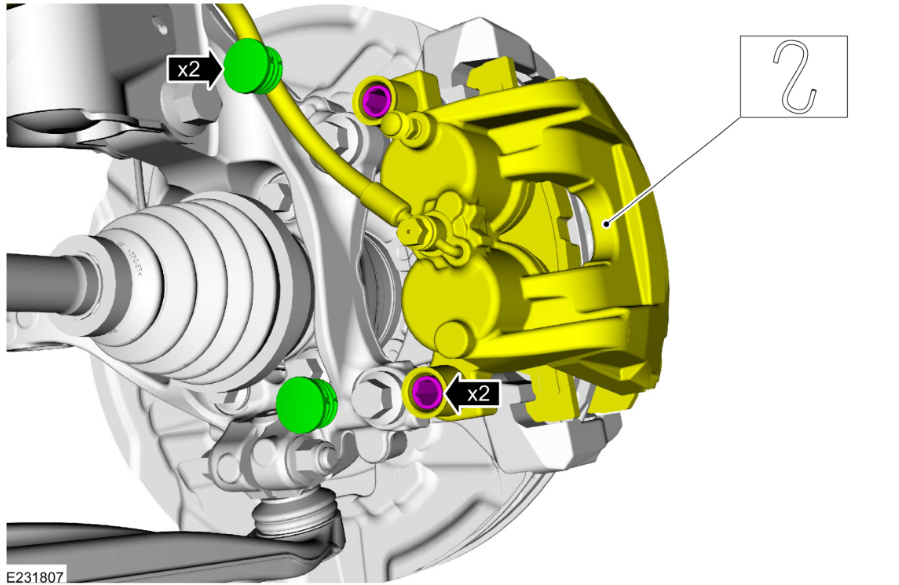
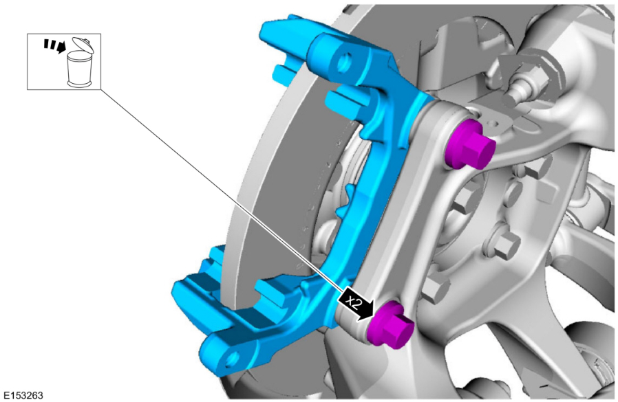
Front Brake Caliper Anchor Plate torque: 111 lb.ft (150 Nm)

Front Brake Disc Shield torque: 106 lb.in (12 Nm)
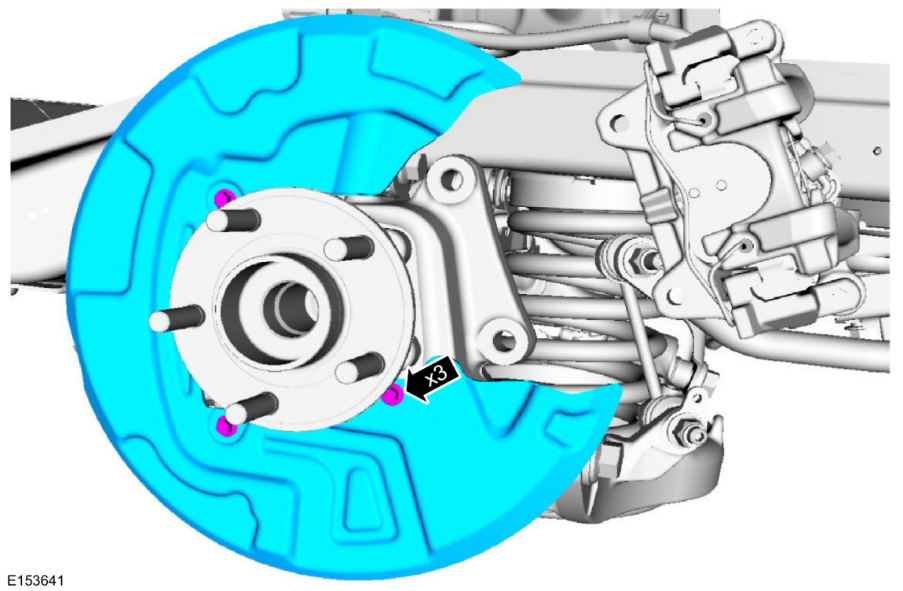
Rear Brake Caliper Flow Bolt torque: 18 lb.ft (25 Nm)
Rear Brake Caliper Guide Pin torque: 21 lb.ft (28 Nm)
Rear Brake Caliper Anchor Plate torque: 66 lb.ft (90 Nm)
Parking Brake Actuator Motor torque: 71 lb.in (8 Nm)
Rear Brake Disc Shield torque: 106 lb.in (12 Nm)
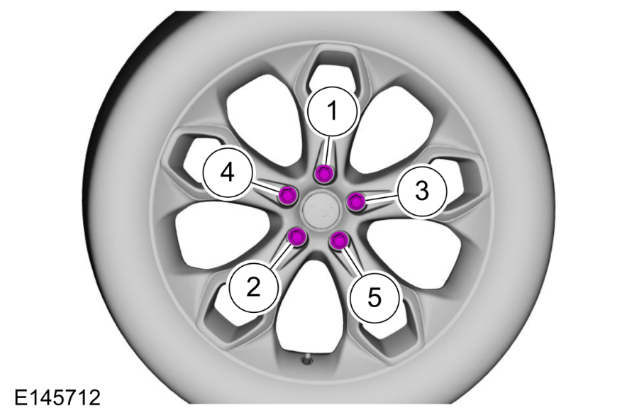
Wheel/Tire torque: 162 lb.ft (220 Nm)
WARNING: Retighten wheel nuts within 160 km (100 mi) after a wheel is reinstalled. Wheels can loosen after initial tightening. Failure to follow this instruction may result in serious injury to vehicle occupant(s).
NOTICE: Failure to tighten the wheel nuts in a star/cross pattern can result in high brake disc runout, which accelerates the development of brake roughness, shudder and vibration.
NOTE: The wheel nut torque specification is for clean, dry wheel stud and wheel nut threads.
NOTE: Final tightening to be performed with vehicle resting on tires.
Good luck!
-
2
-
-
Welcome to the Forum @trickyboy!
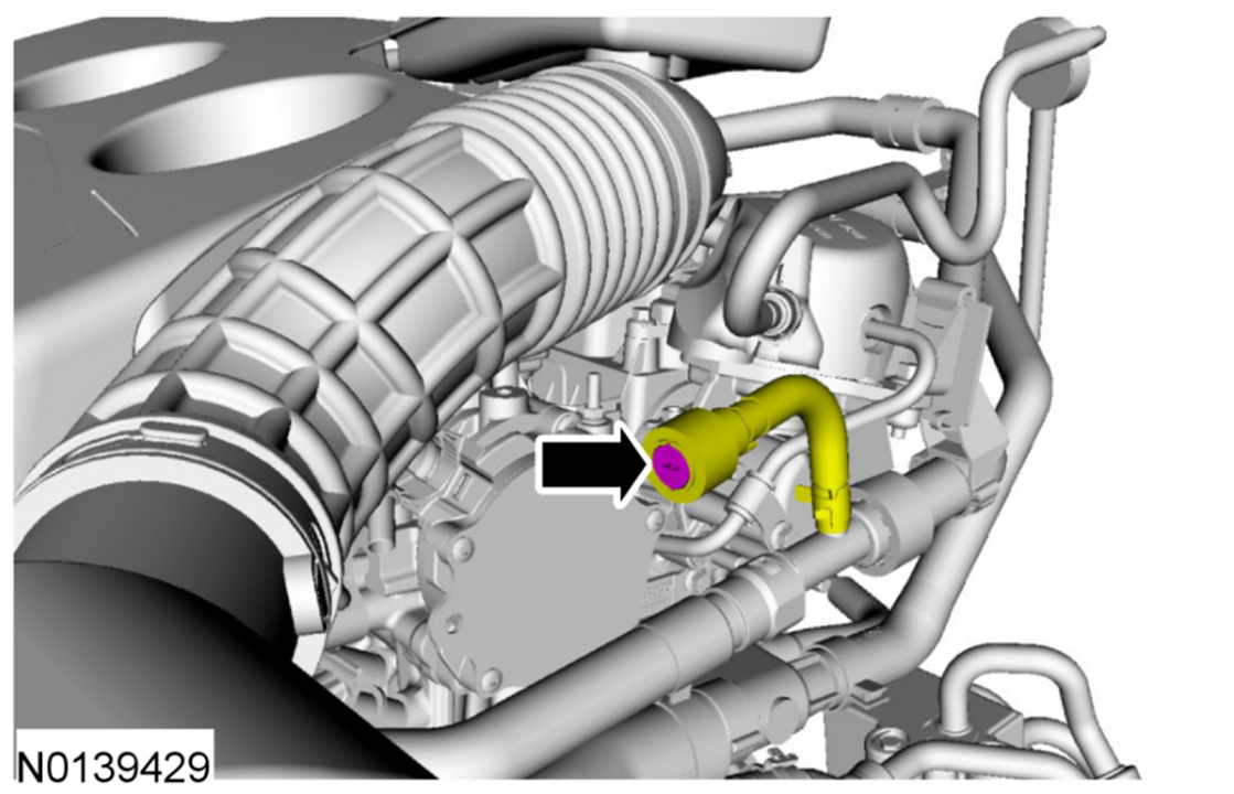
The replacement block heater will be a different design, so that will require performance and durability testing before the new design is placed into production, followed by replacement block heaters flowing to the ordering dealerships, and eventually, to the Hangzhou Assembly Plant in China.
If you are in the USA, it's worth noting that only eleven USA-market 2024-2025 Nautilus vehicles are affected by Safety Recall 52S52, due to their being built with the factory-installed block heater between the specified Build Dates.
Attached below as a PDF document is a National Highway Transportation Safety Administration (NHTSA) report that provides the affected numbers of each vehicle model line involved in Safety Recall 25S52 and the chronology of events that is the 'anatomy' of the recall.
If you are in Canada, the Transport Canada website did not appear to offer any breakdown like the NHTSA report, but your dealer should be able to determine the affected Nautilus number through Ford of Canada.
Has your dealer offered to find you an identical Nautilus that is not factory-equipped with a block heater, and then after you buy that non-Recalled Nautilus, to have their Service department install a new-design block heater, once the revised part is available?
Good luck!
NHTSA Safety Recall Report - Ford 25S52, NHTSA 25V343 - 05-23-2025.pdf
-
1
-
2008 Ford Edge SEL - Ford Remote Starter Module Location
in Alarms, Keyless Entry, Locks & Remote Start
Posted
Welcome to the Forum @DaBlinky!
The sales brochure for the 2008 Edge references availability of a remote start system through Ford Accessories, and the 2008 Edge Workshop Manual offers no technical information, indicating that remote start was a non-factory/dealer-installed feature.
Attached below as PDF documents are installation instructions and a diagnosis guide for the Ford Accessories system, and also the wiring diagram for the standard starting system, without any remote start system.
Good luck!
Remote Start Installation Instructions - 2008 Edge-MKX - Ford Accessories.pdf Ford Powercode Remote Start System - Diagnosis Guide.pdf Conventional (No Remote Start) Starting System - Wiring Diagram - 2008 Edge.pdf