


Haz
-
Posts
1,073 -
Joined
-
Last visited
-
Days Won
265
Content Type
Profiles
Forums
Gallery
Posts posted by Haz
-
-
Welcome to the Forum, billw6560 !
From the 2018 Edge Workshop Manual...
Placing your device cursor over underlined acronyms may yield their full-words description.
Outside Air Temperature
The Ambient Air Temperature (AAT) sensor is hardwired to the PCM through separate input and return circuits. The PCM provides a reference voltage to the Ambient Air Temperature (AAT) sensor and monitors the change in voltage resulting from changes in resistance as determined by outside air temperature.
The PCM sends the ambient air temperature data to the GWM through the HS-CAN1 . The GWM sends the ambient air temperature message to the HVAC (part of the FCIM ) over the MS-CAN . The FCIM filters the data and sends the ambient air temperature filtered data back to the GWM over the MS-CAN . The GWM sends the ambient air temperature filtered message to the IPC over the HS-CAN3.
The FCIM is programmed to update the messaged outside temperature data at different rates depending on several criteria to prevent false temperature displays due to a condition known as heat soaking. Heat soaking is where the outside air temperature is hotter in the location of the Ambient Air Temperature (AAT) sensor than the actual outside air temperature.
The outside air temperature display update strategy requires a starting temperature to update from. This starting temperature is controlled based on the length of time the engine is off and the engine temperature. When the engine has been off for longer than 6 hours, the update strategy begins with the unfiltered ambient air temperature input to the PCM . If the engine has been off for less than 6 hours, and the engine coolant temperature is less than 49° C (120° F), the update strategy begins with the filtered ambient air temperature equal to the unfiltered ambient air temperature. If the engine has been off for less than 6 hours, and the engine coolant temperature is greater than 49° C (120° F), the update strategy begins at the stored previous outside air temperature value.
When the sensed outside temperature rises and the vehicle speed is above 33 km/h (21 mph), the outside air temperature display updates after approximately 90 seconds. As the vehicle speed increases, the outside air temperature display updates at a faster rate that is proportional to the increase in vehicle speed. Once the vehicle speeds exceeds 81 km/h (50 mph), the display updates without any delay. If the vehicle speed drops below 33 km/h (21 mph), the update delays reset. When the sensed outside temperature drops, the display updates more quickly following the drop experienced by the Ambient Air Temperature (AAT) sensor.
The Outside Air Temperature Display Is Inoperative or Incorrect
Normal Operation and Fault Conditions
If the air ambient temperature message is missing or invalid for less than 5 seconds, the IPC defaults the outside air temperature display to the last temperature reading, based upon the last message received.
If the air ambient temperature message is missing or invalid for 5 seconds or longer from the PCM , the IPC displays all dashes (- - ) in the outside air temperature display area.
Possible Sources
- Communication concern
- Ambient Air Temperature (AAT) sensor input to the PCM
- GWM concern
- FCIM concern
PINPOINT TEST AE: THE OUTSIDE AIR TEMPERATURE DISPLAY IS INOPERATIVE OR INCORRECT AE1 PERFORM THE IPC (INSTRUMENT PANEL CLUSTER) SELF-TEST- Ignition ON.
- Using a diagnostic scan tool, perform the IPC self-test.
Are any Diagnostic Trouble Codes (DTCs) recorded?
Yes REFER to DTC Chart: IPC in this section. No GO to AE2
AE2 PERFORM THE FCIM (FRONT CONTROLS INTERFACE MODULE) SELF-TEST- Using a diagnostic scan tool, perform the FCIM module self-test.
Are any Diagnostic Trouble Codes (DTCs) recorded?
Yes Refer to the appropriate section in Group 415 for the procedure. No GO to AE3
AE3 CHECK THE GWM (GATEWAY MODULE A) DIAGNOSTIC TROUBLE CODES (DTCS)- Using a diagnostic scan tool, check the GWM Continuous Memory Diagnostic Trouble Codes (DTCs).
Are any Diagnostic Trouble Codes (DTCs) recorded?
Yes
REFER to: Communications Network (418-00 Module Communications Network, Diagnosis and Testing).No GO to AE4
AE4 PERFORM THE PCM (POWERTRAIN CONTROL MODULE) SELF-TEST- Using a diagnostic scan tool, perform the PCM self-test.
Are any Diagnostic Trouble Codes (DTCs) recorded?
Yes REFER to the appropriate 303-14 section. No GO to AE5
AE5 CHECK THE OUTSIDE AIR TEMPERATURE CONCERN- Verify the customer outside air temperature display concern.
Is the outside air temperature display concern for an incorrect temperature display?
Yes GO to AE6 No

 VIN required to access Guided Routine (IPC)
AE6 CHECK THE AMBIENT AIR TEMPERATURE INPUT TO THE PCM (POWERTRAIN CONTROL MODULE)- Using an infrared temperature scanner or similar tool, measure and record the temperature of the ambient air temperature sensor body.
- Ignition ON.
- Using a diagnostic scan tool, view the PCM Parameter Identifications (PIDs).
- Select the ambient air temperature PID (AAT).
- Monitor the ambient air temperature PID and compare PID value with the recorded temperature of the ambient air temperature sensor body.
Does the ambient air temperature PID match the recorded ambient air temperature sensor measurement within +/- 3° C (+/- 5° F)?
Yes GO to AE7 No GO to AE8
AE7 CHECK THE OUTSIDE AIR TEMPERATURE DISPLAY UPDATE- Drive the vehicle above 33 km/h (20 mph) to allow the outside air temperature display to update.
Did the outside air temperature display update toward the actual ambient air temperature?
Yes The system is operating correctly at this time. Explain to the customer the operation of the system as it relates to the update strategy. No
VIN required to access Guided Routine (FCIM) .
AE8 CHECK THE AMBIENT AIR TEMPERATURE SENSOR RESISTANCE- Ignition OFF.
- Disconnect PCM C1381B (2.0L Engine).
- Disconnect PCM C1551B (2.7L Engine).
- Disconnect PCM C175B (3.5L Engine).

-
Measure:
2.0L Engine
Positive Lead Measurement / Action Negative Lead C1381B Pin 51 C1381B Pin 18

- 2.7L Engine
-
Positive Lead Measurement / Action Negative Lead C1551B Pin 51 C1551B Pin 18

3.7L Engine
Positive Lead Measurement / Action Negative Lead C175B Pin 47 C175B Pin 51

Compare the above ambient temperature sensor resistances using the table below.
Outside Air Temperature Ambient Air Temperature Sensor Value Celsius Fahrenheit Resistance (K ohms) -1.1° to 4.4° 30° to 40° 27.49 to 33.47 4.4° to 10° 40° to 50° 22.06 to 28.86 10° to 15.6° 50° to 60° 16.63 to 23.10 15.6° to 21.1° 60° to 70° 11.74 to 17.32 21.1° to 26.7° 70° to 80° 9.34 to 12.14 26.7° to 32.2° 80° to 90° 8.49 to 9.62 32.2° to 37.8° 90° to 100° 5.93 to 7.87 37.8° to 43.3° 100° to 110° 4.78 to 6.11
Does the resistance match the table specifications above?
Yes GO to AE10 No GO to AE9
AE9 CHECK THE AMBIENT AIR TEMPERATURE SENSOR RESISTANCE- Disconnect Ambient Air Temperature Sensor C132.

-
Measure:
Positive Lead Measurement / Action Negative Lead C132 Pin 1 Component Side C132 Pin 2 Component Side
-
Compare the ambient temperature sensor resistances using the table below.
Outside Air Temperature Ambient Air Temperature Sensor Value Celsius Fahrenheit Resistance (K ohms) -1.1° to 4.4° 30° to 40° 27.49 to 33.47 4.4° to 10° 40° to 50° 22.06 to 28.86 10° to 15.6° 50° to 60° 16.63 to 23.10 15.6° to 21.1° 60° to 70° 11.74 to 17.32 21.1° to 26.7° 70° to 80° 9.34 to 12.14 26.7° to 32.2° 80° to 90° 8.49 to 9.62 32.2° to 37.8° 90° to 100° 5.93 to 7.87 37.8° to 43.3° 100° to 110° 4.78 to 6.11
Does the resistance match the table specifications above?
Yes The ambient air temperature sensor is operating correctly. REPAIR the circuits for high circuit resistance. No GO to AE11
AE10 CHECK THE AMBIENT AIR TEMPERATURE (AAT) SENSOR FOR OBSTRUCTIONS OR DEBRIS- Check the area around the Ambient Air Temperature (AAT) sensor for any obstructions or debris such as leaves or paper.
Is the area around the Ambient Air Temperature (AAT) sensor free from any obstructions or debris?
Yes GO to AE11 No CLEAR all debris or obstructions as necessary to allow for the free flow of air around the Ambient Air Temperature (AAT) sensor.
AE11 CHECK THE AMBIENT AIR TEMPERATURE (AAT) SENSOR OPERATION- Disconnect Ambient Air Temperature (AAT) Sensor C132.
-
Inspect the connector and wiring:
- water intrusion
- corrosion
- damaged pins
- pushed-out pins
Are there any signs of water intrusion, corrosion, damaged or pushed out pins?
Yes REPAIR the Ambient Air Temperature (AAT) sensor connector or wiring for any water intrusion, corrosion, damaged or pushed out pins. No INSTALL a new ambient air temperature sensor.
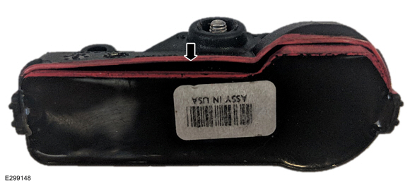
Ambient Air Temperature Sensor Location

Document download links>
Ambient Air Temperature Sensor - Removal and Installation - 2018 Edge Workshop Manual.pdf
Front Bumper Cover - Removal and Installation - 2018 Edge Workshop Manual.pdf
Link to this FordParts webpage


Good luck!
-
 1
1
-
Emphasis added...
SSM 52317 2023 F-Super Duty, 2023-2024 Expedition, 2024 Nautilus/F-150 - Remote Start - No LED Confirmation From The Key Fob After A Remote Start Request 2023 F-Super Duty, 2023-2024 Expedition, 2024 Nautilus/F-150 vehicles will exhibit no light emitting diode (LED) confirmation from the key fob indicating that the vehicle has remote started (or not remote started). Factory key fobs with remote start no longer contain a LED feedback indicator. Do not replace the key fob for this condition. This is a normal operating characteristic and no service action is necessary. -
2
-
-
SSM 52321 2024 Nautilus - Rear Lamp Condensation Some 2024 Nautilus vehicles may exhibit a condition with condensation in the rear body mounted or decklid lamp assemblies that does not affect the function of the lamp. This condition is currently under investigation and replacement of the lamp assemblies may not resolve this condition. Parking the vehicle outside in the sun over several days or in a warm garage may help dissipate the condensation. Continue to monitor OASIS for additional information and schedule service appointments for customers once a repair becomes available. -
2
-
-
SSM 52310 2024 Nautilus/F-150 - Keyless Entry Keypad Code Card Missing Some 2024 Nautilus and F-150 vehicles may incorrectly list the keyless entry keypad code card on the loose item checklist. 2024 Nautilus and F-150 vehicles in North America do not include keyless entry keypad code cards. Clients are now able to retrieve the vehicle's keyless entry keypad master access code in vehicle by following the instructions in the master access code card (available only on F-150) or in the Owner’s Manual > Keyless Entry Keypad Master Access Code. This process requires the use of two programmed intelligent access keys. -
1
-
-
Battery Drain Check
Check
NOTE: The 12 volt battery must be fully charged prior to starting the Battery Drain Check procedure. This procedure should never be conducted if any low battery warning messages such as "deep sleep mode" or "battery saver active" present in the instrument panel cluster. Charge and test the vehicles battery as instructed in the Battery Charging general procedure in this section of the workshop manual prior to conducting the battery drain check procedure.
NOTE: Active OTA software updates (if equipped and enabled) may cause the TCU and/or other modules to remain awake during the drain testing. Using the PTS menu option, locate the connected vehicle>Over The Air Update Dashboard then review the Update Status to see if any OTA are in process. If OTA updates are actively in process, allow the update to complete prior to battery drain testing.
NOTE: No factory-equipped vehicle should have more than a 25 mA (0.025 amp) – 50 mA (0.050) draw depending on the vehicle's accessories. Check for current drains on the battery in excess of 25 mA (0.025 amp) – 50 mA (0.050) with all the electrical accessories off and the vehicle at rest for at least 90 minutes (depending on region and vehicle options). Current drains can be tested with the following procedure.
NOTE: Many electronic modules draw 10 mA (0.010 amp) or more continuously.
NOTE: Typically, a drain of approximately 1 amp is attributed to an engine compartment lamp, glove compartment lamp or interior lamp staying on continually. Other component failures or wiring shorts are located by selectively pulling fuses to pinpoint the location of the current drain. When the current drain is found, the meter reading falls to an acceptable level.
NOTE: To accurately test the drain on a battery, use an in-line ammeter between the negative battery post and its respective cable. Use of a test lamp or voltmeter is not an accurate method.
NOTE: If equipped with an automatic transmission and the vehicle has an IPC PRNDL indicator, verify the gear selector lever is in the park position and is operating correctly. A fault in the park position indicator circuit can prevent modules from transitioning to sleep mode.
NOTE: In addition to the battery drain check, a parasitic draw test video is provided as an additional testing resource:
Click here to view Ford parasitic draw test (Link to extremely thorough, step-by-step online video, which contains no audio commentary)
- Drive the vehicle for at least 5 minutes over 48 km/h (30 mph) to activate the vehicle systems.
- If equipped, disable the approach detection feature.
- If equipped, disable the perimeter alarm feature.
- Park the vehicle, turn the ignition off.
- Open the hood and all doors. Use a flat blade screwdriver (or other suitable tool) to manually close the hood and door latch mechanisms to allow the hood and doors to remain open while drain testing.
-
NOTE: Vehicles may be equipped with multiple fuse box locations.
Make sure the fuse box(es) are accessible without turning on the interior lights or the underhood lights.
Refer to Wiring Diagrams Cell 13 for schematic and connector information.
- If equipped with auxiliary battery(s), ensure that the auxiliary battery(s) are disconnected when measuring current draw at the primary battery, to ensure the meter or inductive amp probe measures all current draws present. Disconnect the auxiliary battery(s). Refer to Battery Disconnect in this section.
- Connect a fused jumper wire (30A) between the negative battery cable and the negative battery post to prevent modules from resetting.
- Disconnect the negative battery cable from the negative battery post without breaking the connection of the fused jumper wire.
- Using the key fob, press the lock button, then move all keys/fobs at least 50 feet away from the vehicle.
-
NOTE: It is important that continuity is not broken between the battery and the negative battery cable when connecting the meter. If this happens, repeat the time out/power down procedure.
NOTE: The meter must be capable of reading milliamps and should have a 10 amp capability.
Connect a meter between the negative battery cable terminal and the negative battery post.
-
NOTE: If the meter settings need to be switched or the test leads need to be moved to another outlet, reinstall the fused jumper wire to avoid breaking continuity.
Remove the fused jumper wire.
- Allow the vehicle to sit with the ignition off for at least 90 minutes (depending on region and vehicle options) to allow the modules to time out/power down.
- Note the amperage draw. Draw varies from vehicle to vehicle depending on the equipment package. Compare to a similar vehicle for reference.
-
NOTE: If the vehicle sits for an extended period of time and the battery drains, there is the possibility of a control module staying alive and not going into sleep mode. If a control module stays alive, it can result in battery drain. If a control module is suspected, isolate individual modules by disconnecting them one at a time and note if the excessive draw goes away.
NOTE: For vehicles equipped with aftermarket equipment containing electrical connections, disconnect the aftermarket to factory connections to isolate the body from the chassis.
If the current draw is excessive, remove the fuses from the main fuse box one at a time and note the current drop.
- When the current level drops to an acceptable level after removing a fuse, the circuit containing the excessive draw has been located. Reinstall the fuse and allow the vehicle to sit with the key out of the ignition for at least 90 minutes (depending on region and vehicle options) to allow the modules to time out/power down again.
- The excessive draw can be isolated by continuing to pull subsystem fuses and disconnecting components. Do not reinstall the fuses or connect components until testing is finished. To correctly isolate each of the circuits, all of the fuses may need to be removed, then install one fuse and note the amperage draw, remove the fuse and install the next fuse. Continue this process with each fuse.
- If excessive current draw is isolated to a specific module, verify if a module input is the cause of the concern. Refer to the corresponding workshop manual system operation and component description section to determine the inputs (hardwired or network messages) received by the module in question.
- Check the Wiring Diagrams manual for any circuits that run from the battery without passing through the main fuse box or other fuse box(es). If the current draw is still excessive, disconnect these circuits until the draw is found. Disconnect the generator(s) electrical connections and retest if the draw cannot be located. The generator(s) may be internally shorted, causing the current drain.
-
If equipped with window one-touch up, perform the window motor initialization after the negative battery cable terminal is connected to the negative battery post.
Refer to: Power Door Window Initialization (501-11 Glass, Frames and Mechanisms, General Procedures).
-
If equipped with power roller shutter, perform the power roller shutter initialization after the negative battery cable terminal is connected to the negative battery post.
Refer to: Power Roller Shutter Initialization (501-04) .
© Copyright 2024, Ford Motor Company.
-

Supplemental information from the Edge Workshop Manual...


-
1
-
-
TSB 23-2356 has been issued, effective February 23, 2024, and it supercedes the above-posted TSB 23-2049, due to updates in the Parts List...
Document download link> TSB 23-2356 - 20019-2023 Edge-Nautilus - 2.7L EcoBoost - Cold Start Ticking-Tapping Or Rattle Type Noise.pdf
TECHNICAL SERVICE BULLETIN
2.7L EcoBoost - Cold Start Ticking/Tapping Or Rattle Type Noise23-2356
23 February 2024This bulletin supersedes 23-2049.
Model:
Ford2019-2023 EdgeEngine: 2.7L EcoBoostLincoln2019-2023 NautilusEngine: 2.7L EcoBoostSummary
This article supersedes TSB 23-2049 to update the parts list.
Issue: Some 2019-2023 Edge/Nautilus vehicles equipped with a 2.7L EcoBoost engine may exhibit a ticking/tapping or rattle type noise from the top front cover area of the engine on initial start-up after a cold soak of 6 hours or more that may last for 2-5 seconds. This may be due to stuck internal components of the variable cam timing (VCT) unit. To correct the condition, follow the Service Procedure to replace the VCT units.
Action: Follow the Service Procedure to correct the condition on vehicles that meet all of the following criteria:
• 2019-2023 Edge/Nautilus
• 2.7L EcoBoost
• Customer symptom of ticking/tapping or rattle noise from the front cover area after a cold start
NOTE: Dealers should only order parts for customer vehicles that require repairs. Because of part constraints, dealers may experience situational short-term backorders on some parts. Customers should continue to drive vehicles while parts are on order.
Parts - All Vehicles - Required Parts
Service Part Number Quantity Description Unit of Issue Piece Quantity CP9Z-6279-C 4 VCT Unit Bolts 1 4 FT4Z-6A340-A 1 Crankshaft Pulley Bolt 1 1 KU2Z-6731-A 1 Engine Oil Filter 1 1 JT4Z-6710-A 1 Oil Pan Press-In-Place Gasket 1 1 KT4Z-6710-A 1 Oil Pan Gasket 1 1 FT4Z-6626-A 1 Oil Pump Seal 1 1 FT4Z-6020-G 1 Coolant Pump Gasket 1 1 FT4Z-8507-C 1 Coolant Pump Seal 1 1 XW4Z-6700-B 1 Crankshaft Front Oil Seal 1 1 FT4Z-6020-K 1 Engine Front Cover Gasket 1 1 1 FT4Z-6020-H 1 Engine Front Cover Gasket 2 1 1 FT4Z-6020-J 1 Engine Front Cover Gasket 3 1 1 FT4Z-6020-A 1 Engine Front Cover Gasket 4 1 1 FT4Z-00815-C 1 Oil Seal 1 1 FT4Z-00815-A 1 Oil Gallery Seal 1 1 L1MZ-6256-C 2 VCT Unit - Intake 1 2 L1MZ-6C525-C 2 VCT Unit - Exhaust 1 2 BL3Z-9450-A 2 Catalytic Converter Gasket 1 2 FT4Z-6584-D 1 Left Valve Cover Gasket 1 1 FT4Z-6584-B 1 Right Valve Cover Gasket 1 1 FT4Z-6584-C 1 Left Valve Cover Gasket 1 1 FT4Z-6584-E 1 Right Valve Cover Gasket 1 1 1X4Z-9E936-AA 1 Throttle Body Gasket 1 1 DL3Z-19B596-B 1 A/C O-Ring Kit 1 1 DS7Z-19B596-A 1 A/C Gasket Kit 1 1 W712334-S440 2 Engine Mount Bracket-To-Engine Nuts 3 4 W717674-S439 1 Engine Mount-To-Frame Bolts 4 2 W710807-S442 1 Engine Mount-To-Frame Nut 4 1 W716457-S439 1 Subframe Bolts 4 4 W712458-S900 1 Exhaust Studs 4 4 W714265-S442 1 Catalytic Converter To Turbo Flange Nuts 4 4 VC-13DL-G As Needed Motorcraft® Yellow Prediluted Antifreeze/Coolant (All Markets Except Canada) CVC-13DL-G As Needed Motorcraft® Yellow Prediluted Antifreeze/Coolant (Canada Only) XO-5W30-Q1SP As Needed Motorcraft® SAE 5W-30 Synthetic Blend Motor Oil (All Markets Except Canada) CXO-5W30-LSP6 As Needed Motorcraft® SAE 5W-30 Super Premium Motor Oil (Canada Only) XL-2 As Needed Motorcraft® High Temperature Nickel Anti-Seize Lubricant ZC-37-A As Needed Motorcraft® Wheel and Tire Cleaner XL-1 As Needed Motorcraft® Penetrating and Lock Lubricant TA-26 As Needed Motorcraft® Threadlock 262 YN-35 As Needed Motorcraft® R-1234yf Refrigerant PAG Oil TA-357 As Needed Motorcraft® High Performance Engine RTV Silicone ZC-30-A As Needed Motorcraft® Gasket Remover ZC-31-B As Needed Motorcraft® Metal Surface Prep Wipes PM-4-A As Needed Motorcraft® Metal Brake Parts Cleaner (Compliant With Low Volatile Organic Compound Requirements As Required In Some USA States) PM-4-B As Needed Motorcraft® Metal Brake Parts Cleaner (Not Compliant With Volatile Organic Compound Requirements) ZC-20 As Needed Motorcraft® Engine Shampoo and Degreaser Parts - Nautilus Only Parts
Service Part Number Quantity Description Unit of Issue Piece Quantity W712961-S450B 1 Steering Shaft Coupler Bolt 4 1 W520215-S440 1 Tie Rod Nut 4 2 W712503-S440 2 Stabilizer Bar Nuts 1 2 W520214-S440 1 Ball Joint Nut 2 2 W500545-S439 1 Ball Joint Stud 4 2 W717016-S439 1 Rearward Subframe Bolt 4 2 Parts - All Vehicles - Parts To Inspect And Replace Only If Necessary
Service Part Number Quantity Description Unit of Issue FT4Z-6A832-C If Needed Oil Filter Housing And Stem 1 BR3Z-6C535-B If Needed Spark Plug Seals 1 Quantity refers to the amount of the service part number required to repair the vehicle.
Unit of Issue refers to the number of individual pieces included in a service part number package.
Piece Quantity refers to the total number of individual pieces required to repair the vehicle.
As Needed indicates the amount of the part may vary and/or is not a whole number. Parts can be billed out as non-whole numbers, including less than 1.
If Needed indicates the part is not mandatory.
Warranty Status: Eligible under provisions of New Vehicle Limited Warranty (NVLW)/Emissions Warranty/Service Part Warranty (SPW)/Special Service Part (SSP)/Extended Service Plan (ESP) coverage. Limits/policies/prior approvals are not altered by a TSB. NVLW/Emissions Warranty/SPW/SSP/ESP coverage limits are determined by the identified causal part and verified using the OASIS part coverage tool.
Labor Times
Description Operation No. Time 2019-2023 Edge AWD 2.7L EcoBoost, Nautilus FWD/AWD 2.7L EcoBoost: Replace All 4 VCT Units (Do Not Use With Any Other Labor Operations) 232356A 14.7 Hrs. Repair/Claim Coding
Causal Part: 6C525 Condition Code: 42 Service Procedure
1. Replace all 4 VCT units. Refer to Workshop Manual (WSM), Section 303-01. Do not replace any additional VCT or engine timing-related components not included in the Parts List.
(1). All the VCT solenoid and spark plug tube seals require inspection, but not all require replacement.
© 2024 Ford Motor Company
All rights reserved.
NOTE: The information in Technical Service Bulletins is intended for use by trained, professional technicians with the knowledge, tools, and equipment to do the job properly and safely. It informs these technicians of conditions that may occur on some vehicles, or provides information that could assist in proper vehicle service. The procedures should not be performed by "do-it-yourselfers". Do not assume that a condition described affects your car or truck. Contact a Ford or Lincoln dealership to determine whether the Bulletin applies to your vehicle. Warranty Policy and Extended Service Plan documentation determine Warranty and/or Extended Service Plan coverage unless stated otherwise in the TSB article. The information in this Technical Service Bulletin (TSB) was current at the time of printing. Ford Motor Company reserves the right to supersede this information with updates. The most recent information is available through Ford Motor Company's on-line technical resources.
-
1
-
-
SSM 52285 - 2024 Nautilus - Battery State Of Charge Must Be Over 70% Before Delivery To Customers Some 2024 Nautilus vehicles may exhibit low battery state of charge that may be attributed to extended transit times from the assembly plant to the dealerships. It is critical that the battery state of charge (SOC) is above 70% before delivery to the customers. The Lincoln electronic pre-delivery inspection (ePDI) process should be fully completed, which includes battery state of charge checks. Do not utilize the ePDI IDS override function to bypass these checks. If SOC is below 70% the battery must be charged with the charger's negative clamp on an engine or chassis ground. Refer to the Warranty and Policy Manual, Section 2.9.00 Storage of New Vehicles for battery charging warranty guidelines.
-
1
-
-
SSM 52287 2021-2022 Edge - Inoperative Sirius Satellite Radio With ACM Diagnostic Trouble Code (DTC) B1A89:13 Some 2021-2022 Edge vehicles may exhibit an inoperative Sirius satellite radio with audio control module (ACM) DTC B1A89:13. This may be due to the accessory protocol interface module (APIM) configuration. To correct the concern, download and run the APIM Programmable Module Installation (PMI) application. When the application asks Is The Original Module Installed, select NO. Once the programming completes, clear the DTCs. For claiming, use causal part 14G670 and applicable labor operations in Section 10 of the Service Labor Time Standards (SLTS) Manual.
-
2
-
-
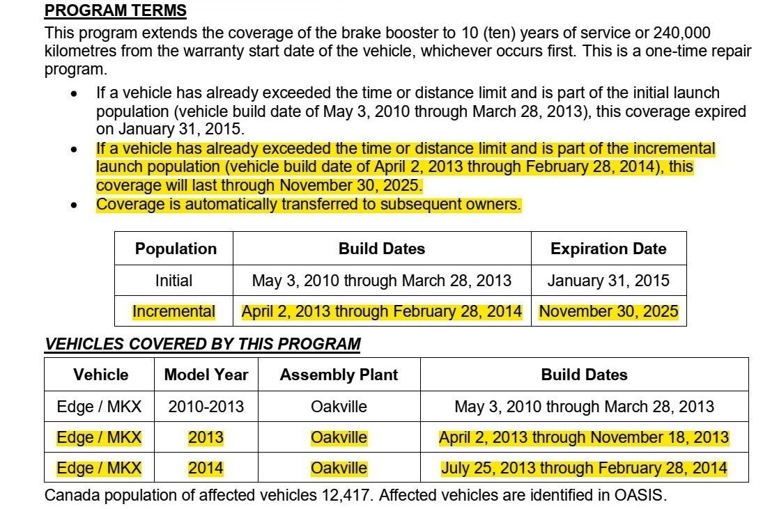
Canadian 2013 & 2014 Edge/MKX owners also benefit from CSP 13N02's extended Refund Program for owner-paid Brake Boost repairs...
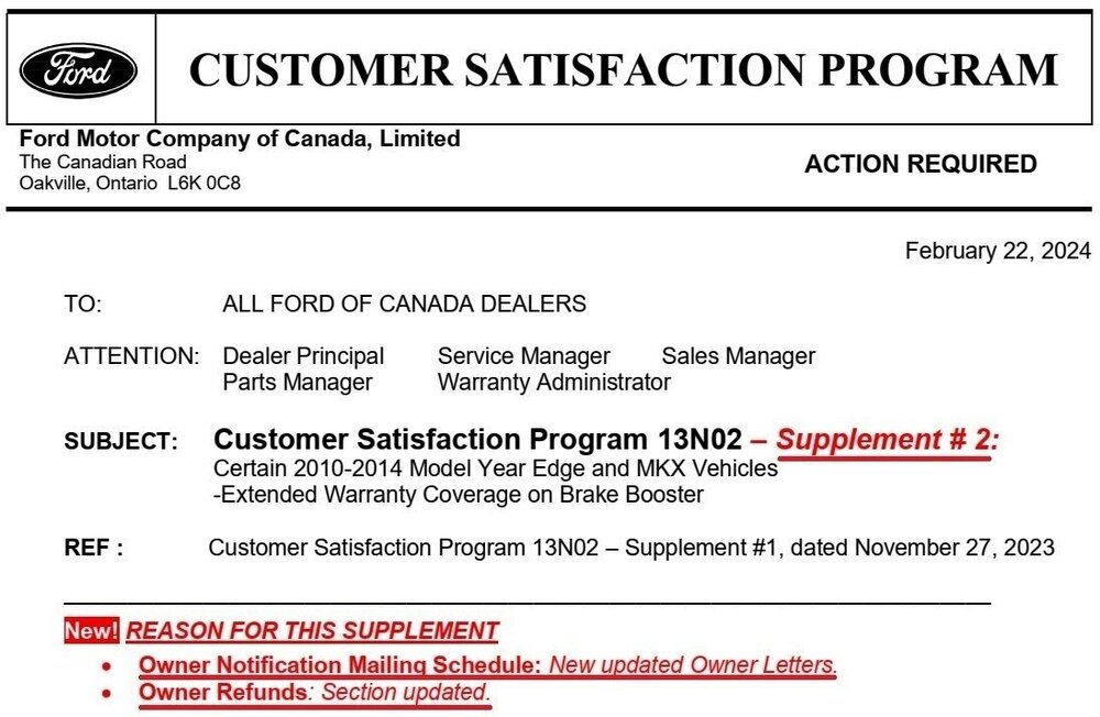


Document download link> Canada Customer Satisfaction Program 13N02 Supplement #2 - Owner Letter - March 2024.pdf
-
1
-
-
Perhaps take your ST to the dealership the evening before its Service appointment, so the technician can test drive it from a cold start when the transmission noise is most evident.
Since your ST is beyond its 5 -year/60,000 mile Powertrain warranty, likely the only thing you'll pay is your Ford ESP PremiumCARE deductible -- if your contract includes one.
On a tangent -- That Marauder must look really good on the streets of Yonkers.
Good luck!
-
From the 2024 Edge Workshop Manual...
(Placing your device cursor over underlined acronyms may yield full-words descriptions)
DRL
For base series headlamps, the DRL system illuminates the low beam Light Emitting Diodes (LEDs) at a reduced intensity.
For mid and high series headlamps, the DRL system illuminates the LED DRL /front parking lamps at full intensity in the headlamp assembly when the ignition is on, the headlamp switch is in the OFF or AUTOLAMPS position and the headlamps have not been turned on by the autolamp system.
For vehicles equipped with a bull bar, the DRL system illuminates the DRL mounted in the bull bar.
When the ignition is in ON, the BCM supplies voltage to each headlamp assembly.
The BCM monitors the ignition status, the headlamp switch and autolamp status.
There are two types of DRL , conventional (where it is required) and configurable.
When equipped with conventional DRL , the DRL are active in any headlamp switch position except the HEADLAMPS position.
The conventional DRL are activated when the following conditions are met:
- the ignition is ON
- the headlamps switch is in OFF, PARKLAMPS or AUTOLAMPS position and the headlamps have not been turned on by the autolamp system.
- the transmission is not in PARK
When equipped with configurable DRL , the DRL may be enabled through the IPC message center. When enabled, the DRL are active only in the AUTOLAMPS headlamp position. When autolamps request the headlamps on, the DRL are de-activated.
The configurable DRL are activated when the following conditions are met:
- the ignition is ON.
- the headlamps switch is in AUTOLAMPS position and the headlamps have not been turned on by the autolamp system.
- the transmission is not in PARK.
When the transmission is in not in PARK, the PCM sends a message over the HS-CAN1 to the BCM indicating the transmission is not in PARK.
The BCM also provides Field Effect Transistor (FET) protection of the DRL output circuits. When an excessive current draw is detected, the BCM disables the affected circuit driver.
Because yours is a Canadian-market Edge, where Daytime Running Lights are an always-on Transport Canada requirement, the above "configurable DRL" ability is not provided.
Good luck!
-
3
-
From the 2011 Edge Workshop Manual...
(Placing your device cursor over underlined acronyms may display the item's full-words description)
Parking Aid — Video
Principles of Operation
NOTE: Close the liftgate for correct operation of the video camera system.
The rear video camera system is active with the ignition in run and the transaxle selector in the REVERSE (R) position. The video camera receives commands and sends status over a dedicated Local Interconnect Network (LIN) to the Body Control Module (BCM) . The video camera sends a video signal to the Accessory Protocol Interface Module (APIM) on a pair of shielded video circuits. The APIM sends the video signal to the Front Display Interface Module (FDIM) (mounted to the APIM ) which displays the video image of the area behind the vehicle.
The video camera system has 4 video features that are controlled in the FDIM . The features are:
- Fixed guidelines
- Visual park aid alert
- Manual zoom
- Video camera delay
For each one of these system features except the camera delay feature, the APIM sends a network message requesting the system feature to the Instrument Panel Cluster (IPC) via the High Speed Controller Area Network (HS-CAN) . The IPC sends the message to the BCM over the HS-CAN . The BCM sends the message to the video camera over the LIN . The LIN is a dedicated single wire communication line that sends and receives network messages from the BCM to the video camera. The video camera delay feature is controlled with in the APIM .
The messages sent from the BCM to the video camera are:
- transmission selector (PRNDL) status
- liftgate ajar status
- camera configuration data
- display manual zoom request
- parking aid audible warning status
- parking aid sensor distance to object data
The messages sent from the video camera to the BCM are:
- camera status
- display zoom status
- camera part number data
- visual park aid alert status
- fixed guideline status
All of the video camera features are enabled and disabled within the FDIM menu screen.
The video camera delay feature keeps the image displayed on the FDIM until the vehicle reaches 8 km/h (5 mph) when the vehicle is shifted out of reverse or if any button on the FDIM is pressed.
The video camera fixed guidelines feature displays guidelines on top of the video image to assist the driver with alignment of the vehicle. A dashed line on the displayed image represents the center of the vehicle and 3 color-coded lines (red, yellow, green) identify different zones between the rear of the vehicle and objects.
NOTE: The color-coded lines cannot indicate accurate or consistent distances between objects located behind the vehicle and at the rear of the vehicle. This normal condition is due to variances in vehicle ride height, including, but not limited to, vehicle loading.
The visual park aid alert feature utilizes the 4 parking aid sensor inputs from the Parking Aid Module (PAM) and the video camera image. When the transaxle selector is in the reverse position and an object is detected in the path of the parking aid sensor, a network message of the distance from the parking aid sensor to the object is sent from the PAM to the BCM over the HS-CAN . The BCM networks the parking aid sensor message to the video camera over the LIN . The visual alerts are red, yellow or green and appear as highlights on top of the displayed image to indicate in which zone the object is detected. The highlighted visual alerts are still operational if the parking aid system is disabled within the IPC and the visual alert feature is enabled.
The manual zoom feature is controlled by the video camera. The manual zoom feature has 3 zoom levels that are only active when the vehicle is in reverse. If the manual zoom feature is enabled and the vehicle is shifted out of reverse the manual zoom feature is disabled. The manual zoom feature must be re-enabled the next time the vehicle is shifted into reverse. When the FDIM requests the video image to be zoomed in or out, the APIM sends a zoom request network message to the IPC . The IPC sends the message to the BCM , which sends the zoom request message to the video camera over the LIN . The video image sent by the video camera is then digitally zoomed in or out.
Because you indicate no Diagnostic Trouble Codes (DTCs) are present in any of your Edge's electronic modules, we look to the Symptom Chart for diagnostic procedure guidance...


Pinpoint Test I: Visual Park Aid Is Inoperative
Refer to Wiring Diagrams Cell 131 , Parking Aid for schematic and connector information...
Normal Operation
When the transaxle selector in the reverse position and an object is detected in the path of the parking aid sensor, a network message of the distance from the parking aid sensor to the object is sent from the Parking Aid Module (PAM) to the Body Control Module (BCM) over the High Speed Controller Area Network (HS-CAN) . The BCM networks the parking aid sensor message over the Local Interconnect Network (LIN) to the video camera. The visual alerts are red, yellow or green and appear as highlights on top of the displayed image to indicate in which zone the object is detected. The visual park aid feature can be enabled and disabled with in the Front Display Interface Module (FDIM) .
This pinpoint test is intended to diagnose the following:
- Wiring, terminals or connectors
- Video camera
- PAM
- BCM
PINPOINT TEST I : VISUAL PARK AID IS INOPERATIVE NOTICE: Use the correct probe adapter(s) when making measurements. Failure to use the correct probe adapter(s) may damage the connector. I1 VERIFY THE VISUAL PARK AID IS ENABLED- Verify that the visual park aid is enabled in the FDIM .
Is the visual park aid enable in the FDIM ?
Yes GO to I2. No ENABLE the visual park aid. TEST the system for normal operation.
I2 CHECK THE DTCS FROM THE PAM SELF-TEST- Check the PAM DTCs from the self-test.
Are any PAM DTCs recorded?
Yes REPAIR all PAM DTCs first. REFER to Parking Aid in this section. TEST the system for normal operation. No GO to I3.
I3 CHECK THE DTCS FROM THE BCM SELF-TEST- Check the BCM DTCs from the self-test.
Are any BCM DTCs recorded?
Yes REFER to DTC Charts in this section. No GO to I4.
I4 CHECK FOR CORRECT VIDEO CAMERA OPERATION- Connect: All Disconnected Connectors .
- Disconnect the video camera connector.
-
Check for:
- corrosion
- damaged pins
- pushed-out pins
- Connect the video camera connector and make sure it seats correctly.
- Operate the system and verify the concern is still present.
Is the concern still present?
Yes INSTALL a new video camera. REFER to Video Camera in this section. TEST the system for normal operation. No The system is operating correctly at this time. The concern may have been caused by a loose or corroded connector.
If any DTCs surface after you use Forscan to specifically perform module Self Tests on the PAM and BCW, then report them back here and we'll address them further.
You may notice in all of the above explanation that the Camera's generating the red -yellow-green visual cues is the result of the BCM messaging across the LIN circuit.
The wiring diagram indicates the LIN circuit passes through three connectors between the Camera and the BCM: at C4357 Pin 2, at C495 Pin 2, and at C919 Pin 9.
Connector details and location illustrations are linked for download below.
If you progress to Step I4, you may want to inspect all three of those Connectors/LIN circuit Pins for corrosion and/or a pushed-out conditions.
And finally, about your "eBay special" "OEM" camera purchase.
Is the camera outwardly identical to the camera you removed, showing identical part number and manufacturer markings?
Have you contacted the eBay seller for a replacement camera?
Document download links>
VIDEO CAMERA - Connector C4357 Details - 2011 Edge.pdf
Inline Connector C495 - Body Harness to Camera Jumper Harness - 2011 Edge.pdf
Video CAMERA - Connectors C495 & C4357 Locations in Liftgate - 2011 Edge.pdf
Inline Connector C919 - Liftgate Harness to Body Harness Details - 2011 Edge.pdf
Inline Connector C919 - Liftgate Harness to Body Harness Location - 2011 Edge.pdf
Inline Connector C919 - Liftgate Harness to Body Harness Location, Alternate View - 2011 Edge.pdf
Good luck!
-
1
-
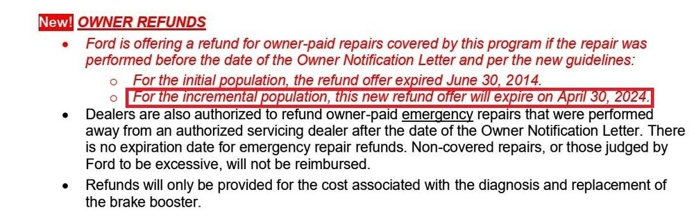
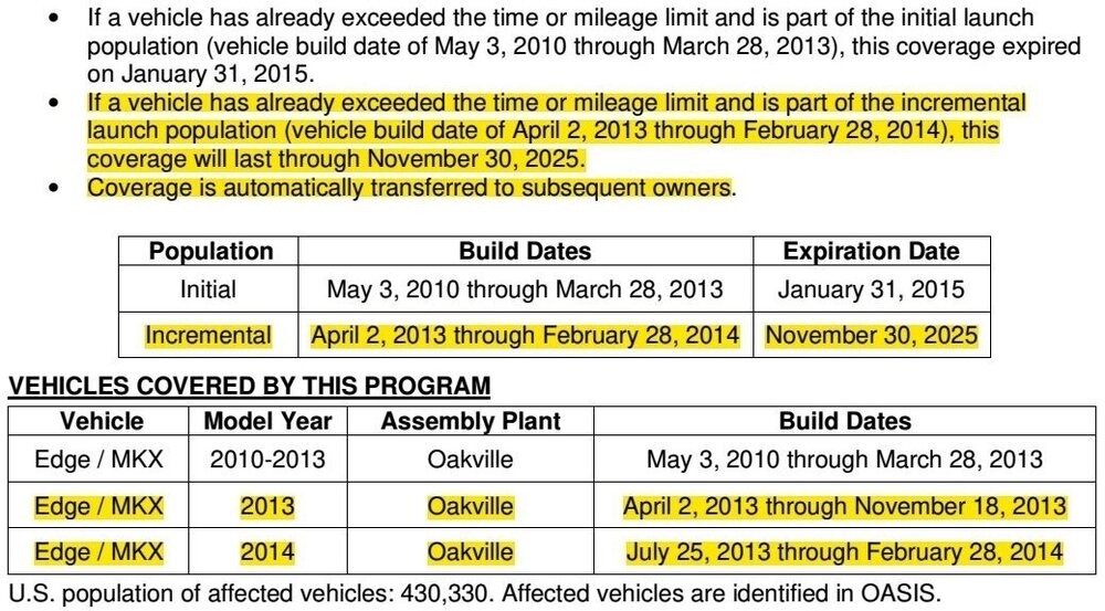
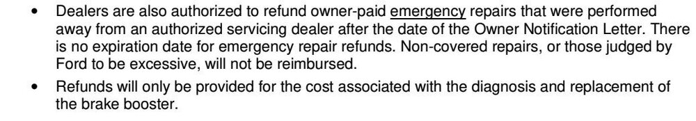
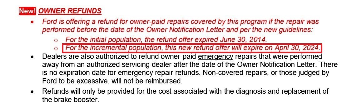
Program 13N02's refunds for past owner-paid repairs to incremental population 2013 & 2014 Edge/MKX vehicles is being extended to April 30, 2024.
Updated letters to owners of incremental population 2013 & 2014 Edge/MKX vehicles will be mailed the week of March 18, 2024.
For more information, see...
Good luck!
-
2
-
-
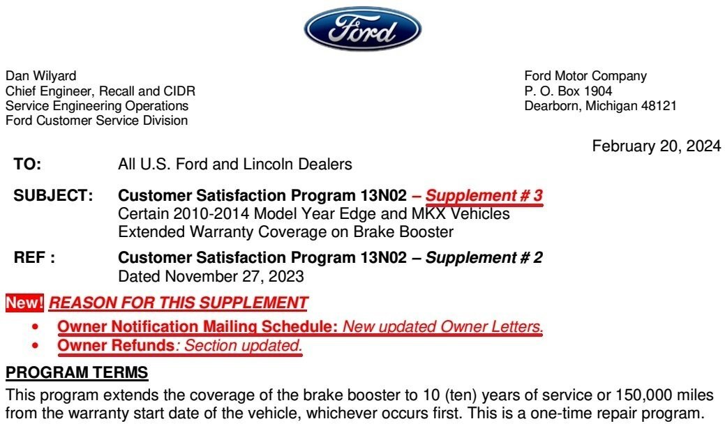
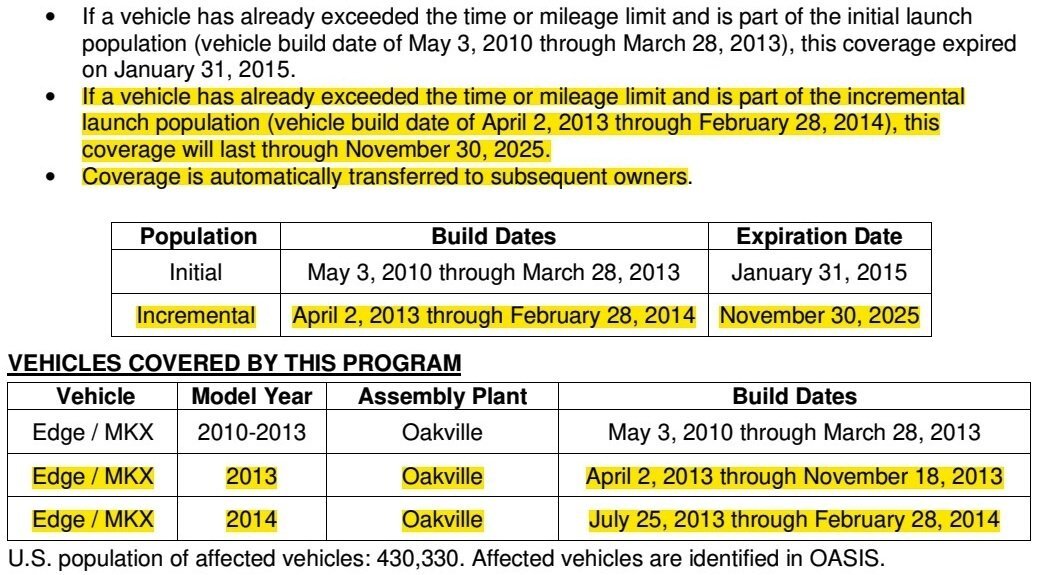
Supplement #3 Highlights
- Updated letters to owners of incremental population 2013 & 2014 Edge/MKX vehicles will be mailed the week of March 18, 2024.
- Refunds for past owner-paid repairs to incremental population of 2013 & 2014 Edge/MKX vehicles extended to April 30, 2024.


Document download links to samples of updated letter being sent to Owners of the incremental population of 2013 & 2014 Edge/MKX vehicles>
Customer Satisfaction Program 13N02 Supplement #3 - Ford Owner Letter - March 2024.pdf
Customer Satisfaction Program 13N02 Supplement #3 - Lincoln Owner Letter - March 2024.pdf
-
2
-
I'm unsure how the numbering in these illustrations coincides with the sequencing of the Walk Test, but at least all speaker locations are depicted here...
6-Speaker System


12-Speaker System


Good luck!
-
2
-
-
Hands Free Liftgate is no longer offered on any trim level of the 2024 Lincoln Corsair, the 2025 Ford Explorer, nor the 2025 Lincoln Aviator.
-
SSM 52268 2024 Nautilus - U2300:29 Setting In The PSCM When A Diagnostic Self-Test Is Performed Some 2024 Nautilus vehicles may exhibit diagnostic trouble code (DTC) U2300:29 in the power steering control module (PSCM) when a diagnostic self-test is performed. This may be due to an internal counter reaching a specified timeframe. The history state DTC U2300:29 has no effect on functionality. Replacement or reprogramming of the PSCM will not resolve this condition. DTC U2300:29 should be ignored if: no other DTCs are present in the PSCM, no warning indicators are illuminated while the engine is running with no effect on vehicle operation, and no symptoms present. No further service action is required. -
1
-
-
While the 2024 Nautilus continues offering Hands Free Liftgate as standard equipment on Premier (102A), Reserve (202A & 203A), and Black Label (800A) trim levels, this announcement is notable...
SSM 52269 Multiple Vehicle Lines - No Longer Equipped With A Hands Free Liftgate System 2022-2024 Explorer/Aviator vehicles built on or after 28-May-2022, 2022-2024 Expedition/Navigator vehicles built on or after 08-Jun-2022, 2022-2024 Escape vehicles built on or after 01-Jun-2022 and 2022 Corsair vehicles built on or after 01-Jun-2022 are no longer equipped with a hands free liftgate system. The vehicle is not misbuilt. The addition of any parts is not a warrantable repair. Do not submit a claim for this condition. -
1
-
 1
1
-
-
SSM 52270 2024 Nautilus - Liftgate Illuminated Lincoln Lettering 2024 Nautilus vehicles are equipped with a rear deck lid lamp with Lincoln lettering. On Black Label trim level vehicles only, this Lincoln lettering will illuminate and all other trim levels this Lincoln lettering will not illuminate. This feature becomes illuminated on Black Label trim vehicles when the exterior lamps are on with the vehicle is in park. This feature shuts off and the letters will no longer illuminate when the vehicle comes out of park. This is normal operation and no repair attempts should be performed for this condition.
Supplemental photo from a Lincoln source, apart from SSM 52270 release...

-
2
-
-
GENERAL SERVICE BULLETIN 23-7172 - Tire Pressure Monitoring Systems (TPMS) Identification
Issued February 15, 2024This bulletin supersedes 19-7001.
Summary
This article supersedes GSB 19-7001 to update the vehicle model years affected and Service Information.
This bulletin contains information on TPMS identification of Ford versus non-Ford sensors along with warrantable versus non-warrantable concerns and examples.
Service Information
Tires Overview
Tires are designed to operate within a specific range of air pressures. The recommended inflation pressure is printed on the decal on the driver's door jamb (B-Pillar). The decal specifies the proper tire inflation.
Tire pressure should be checked monthly as recommended in the Owner's Manual because all tires lose pressure over time.
A tire's inflation pressure cannot be judged by appearance alone. By the time a low profile radial tire looks low, it may already be 10 to 15 PSI underinflated.
The accuracy of some new inexpensive tire pressure gauges can be off by several PSI. Checking tire inflation pressure requires an accurate tire pressure gauge.
TPMS Technology
When the vehicle begins to move, a switch inside the sensor activates the pressure measurement and signal sending function. At about 20 mph (32 km/h), the sensor begins measuring the pressure every 30 seconds and transmits the results once each minute to the control module.
The sensors transmit tire pressure data to the control module at 315 MHz or 433 MHz depending on the vehicle model year. Trailer TPMS and most export vehicles use 433 MHz.
After inflating the tires to the recommended inflation pressure, the vehicle must be driven at 20 mph (32 km/h) or more for a few minutes for the light to turn off.
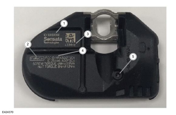
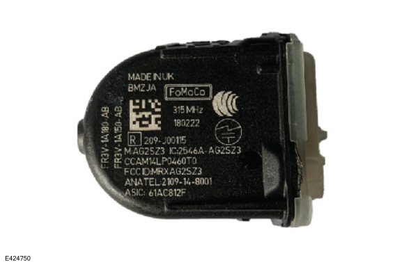
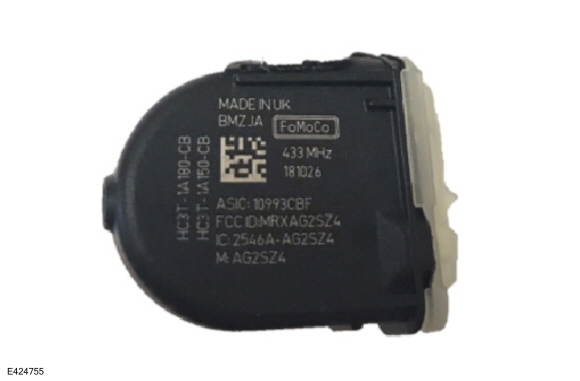
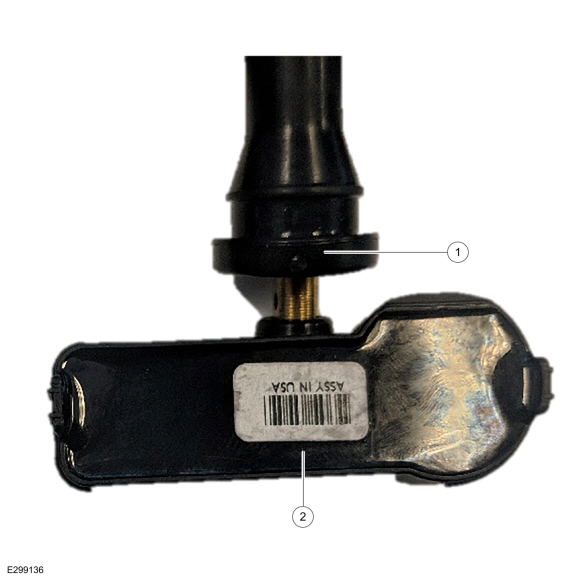
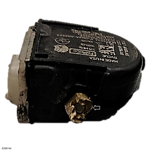
Ford Original Equipment (OE) Sensor (Edison Housing) Markings And Part Details (Figures 1-2)
Figure 1
Item Description 1 Sensor ID
2 Ford Part Number
3 Sensor Build Date (Year/Month/Day)
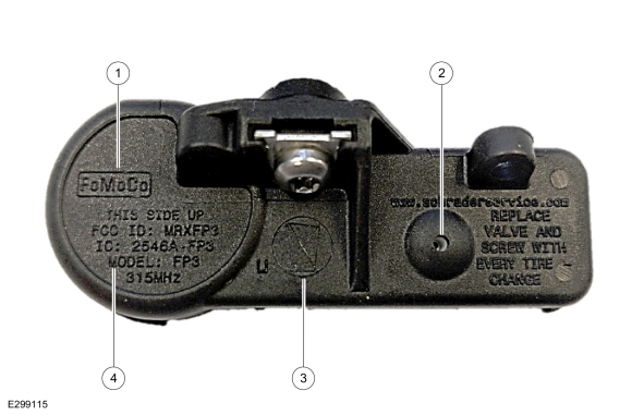
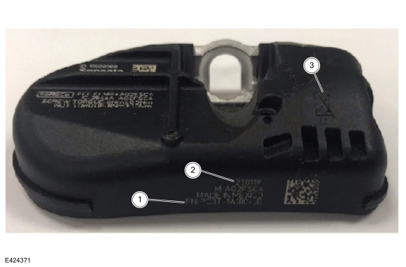
Figure 2
Item Description 1 FoMoCo Label
2 Pressure Port
3 Do Not Discard Warning
4 FCC Identification and Frequency
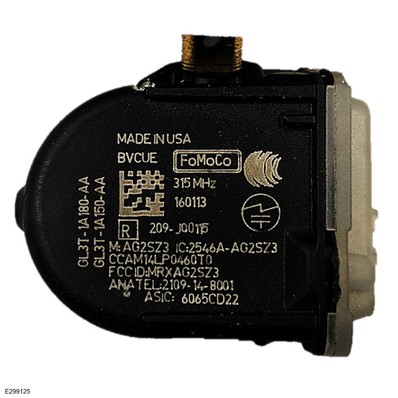
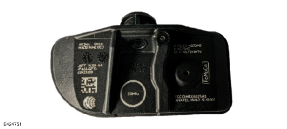
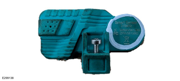
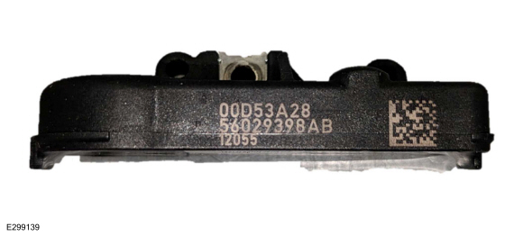
Ford OE Sensor (Potted Faraday) Markings And Part Details (Figures 3-4)
Figure 3
Item Description 1 Sensor ID
2 Ford Part Number
3 Sensor Build Date (Year/Month/Day)
Figure 4
Item Description 1 FoMoCo Label
2 Pressure Port
3 Do Not Discard Warning
4 FCC Identification and Frequency
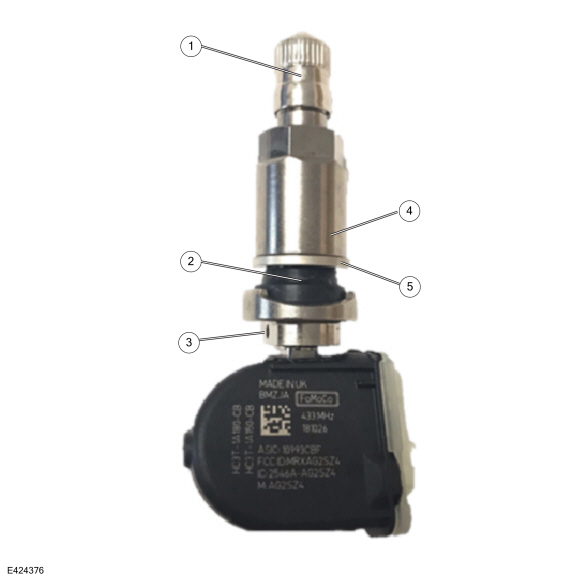
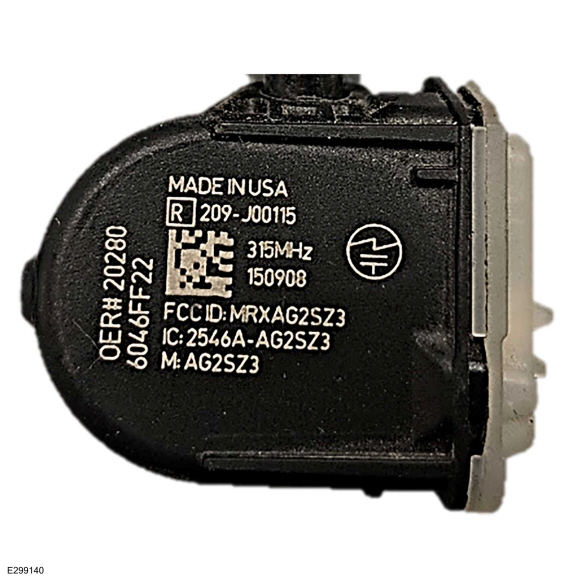
Ford OE Sensor (Faraday) Markings And Part Details (Figures 5-6)
Figure 5
Item Description 1 FoMoCO Label
2 Sensor Frequency
3 Sensor Build Date (Year/Month/Day)
4 Pressure Port
5 Sensor ID
6 FCC Identification
7 Ford Part Number
Figure 6
Item Description 1 Do Not Discard Warning
2 Visual Identifier (Part Specific)
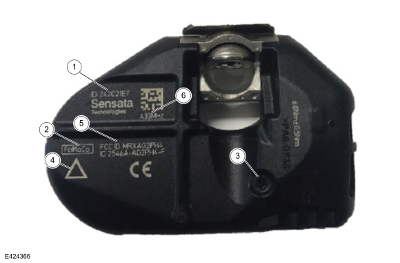
Ford OE Sensor (MHSSI) Markings And Part Details (Figures 7-8)
Figure 7
Item Description 1 Sensor ID
2 Ford Part Number
3 Sensor Build Date (Year/Month/Day)
4 Visual Identifier (Part Specific)
5 Sensor Frequency
6 FCC Identification
7 FoMoCo Label
8 Pressure Port
Figure 8
Item Description 1 Do Not Discard Warning
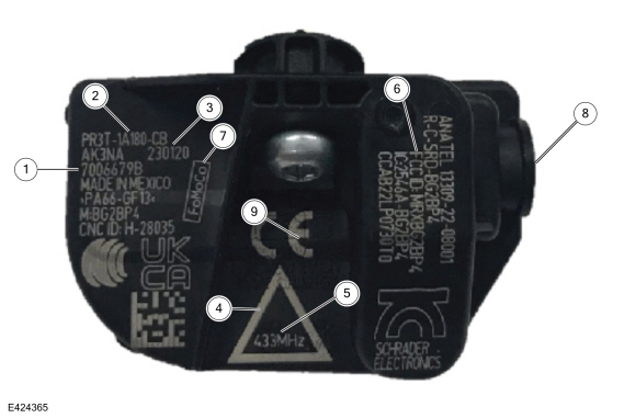
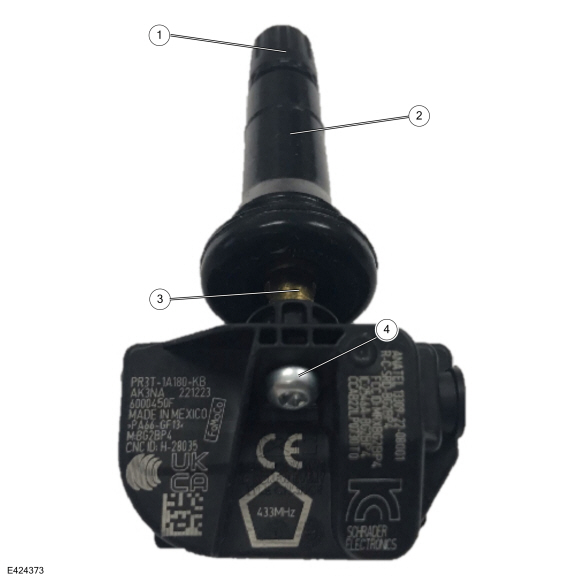
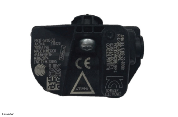
Ford OE Sensor (Burnell) Markings And Part Details (Figure 9)
Figure 9
Item Description 1 Sensor ID
2 Ford Part Number
3 Sensor Build Date (Year/Month/Day)
4 Visual Identifier (Part Specific)
5 Sensor Frequency
6 FCC Identification
7 FoMoCo Label
8 Pressure Port
9 Do Not Discard Warning
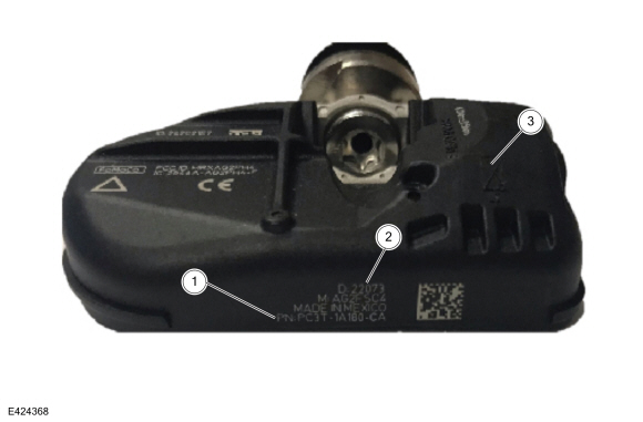
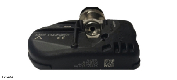
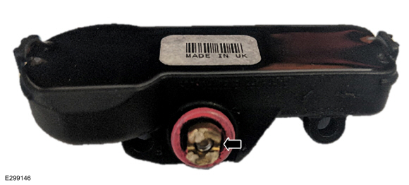
Ford OE Sensor (Steel Carcass) Markings And Part Details (Figures 10-11)
Figure 10
Item Description 1 Sensor ID
2 FoMoCo Label
3 Pressure Port
4 Visual Identifier (Part Specific)
5 FCC Identification
6 Sensor Frequency
Figure 11
Item Description 1 Ford Part Number
2 Sensor Build Date (Year/Month/Day)
3 Do Not Discard Warning
Ford OE Sensor (Trailer) Markings And Part Details (Figures 12-13)
Figure 12
Item Description 1 Ford Part Number
2 Sensor Build Date (Year/Month/Day)
3 Sensor ID
4 Sensor Frequency
5 FoMoCo Label
6 FCC Identification
Figure 13
Item Description 1 Pressure Port
2 Do Not Discard Warning
Ford OE Sensor (Trailer Steel Carcass) Markings And Part Details (Figures 14-15)
Figure 14
Item Description 1 Sensor ID
2 FoMoCo Label
3 Sensor Frequency
4 FCC Identification
5 Pressure Port
Figure 15
Item Description 1 Ford Part Number
2 Sensor Build Date (Year/Month/Day)
3 Do Not Discard Warning
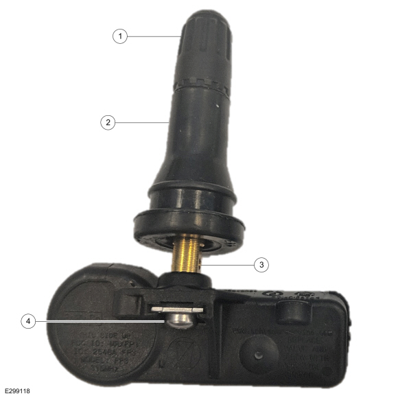
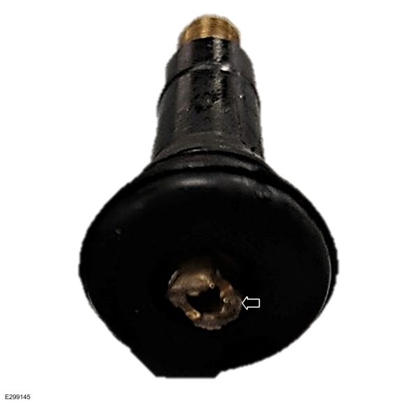
Ford OE Sensor (Edison/Faraday) Components (Figures 16-17)
NOTE: When replacing the valve, make sure to replace the valve only, not the entire sensor kit. Otherwise, this is an over-repair and not warrantable.
Figure 16
Item Description 1 Cap
2 Valve Stem
3 Valve Air Port
4 Bolt
Figure 17
Item Description 1 Cap
2 Valve Stem
3 Valve Air Port
4 Bolt
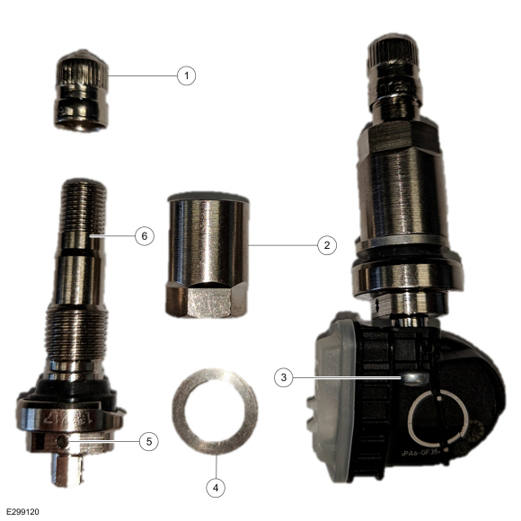
Ford OE Sensor (Bolt-On Faraday) Components (Figure 18)
NOTE: When replacing the valve, make sure to replace the valve only, not the entire sensor kit. Otherwise, this is an over-repair and not warrantable.
Figure 18
Item Description 1 Cap
2 Hex Nut
3 Bolt
4 Washer
5 Valve Air Port
6 Valve Stem
Ford OE Sensor (MHSSI) Components (Figure 19)
NOTE: When replacing the valve, make sure to replace the valve only, not the entire sensor kit. Otherwise, this is an over-repair and not warrantable.
Figure 19
Item Description 1 Cap
2 Valve Stem
3 Valve Air Port
4 Bolt
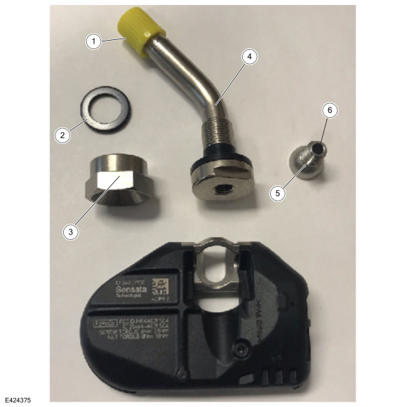
Ford OE Sensor (Burnell) Components (Figure 20)
NOTE: When replacing the valve, make sure to replace the valve only, not the entire sensor kit. Otherwise, this is an over-repair and not warrantable.
Figure 20
Item Description 1 Cap
2 Valve Stem
3 Valve Air Port
4 Bolt
Ford OE Sensor (Steel Carcass - Straight) Components (Figure 21)
NOTE: When replacing the valve, make sure to replace the valve only, not the entire sensor kit. Otherwise, this is an over-repair and not warrantable.
Figure 21
Item Description 1 Washer
2 Hex Nut
3 Cap
4 Valve Stem
5 Bolt
6 Valve Air Port (flows through bolt)
Ford OE Sensor (Steel Carcass - Bent) Components (Figure 22)
NOTE: When replacing the valve, make sure to replace the valve only, not the entire sensor kit. Otherwise, this is an over-repair and not warrantable.
Figure 22
Item Description 1 Cap
2 Washer
3 Hex Nut
4 Valve Stem
5 Bolt
6 Valve Air Port (flows through bolt)
Ford OE Sensor (Trailer) Components (Figure 23)
NOTE: When replacing the valve, make sure to replace the valve only, not the entire sensor kit. Otherwise, this is an over-repair and not warrantable.
Figure 23
Item Description 1 Cap
2 Valve Stem
3 Valve Air Port
4 Hex Nut
5 Washer
Ford OE Sensor (Trailer Steel Carcass) Components (Figure 24)
NOTE: When replacing the valve, make sure to replace the valve only, not the entire sensor kit. Otherwise, this is an over-repair and not warrantable.
Figure 24
Item Description 1 Cap
2 Valve Stem
3 Washer
4 Hex Nut
5 Bolt
6 Valve Air Port (flows through bolt)
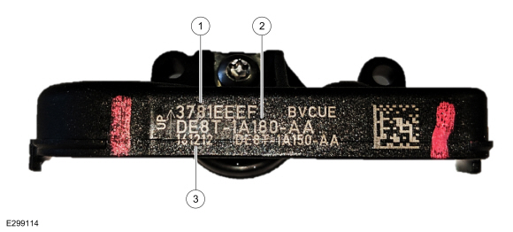
Identifying Correct Ford OE Sensor (DE8T / Edison) For A Particular Vehicle (Figure 25)
Figure 25
1 - DE8T-1A180-**
Engineering Part Number Description DE8T-1A180-** 315 MHz Edison Identifying Correct Ford OE Sensor (GL3T / Faraday) For A Particular Vehicle (Figure 26)
Figure 26
2 - GL3T-1A180-**
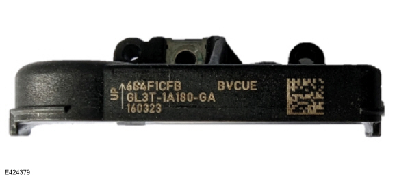
Engineering Part Number Description GL3T-1A180-AA 315 MHz Faraday GL3T-1A180-CA 433 MHz Faraday Identifying Correct Ford OE Sensor (GL3T / Potted Faraday) For A Particular Vehicle (Figure 27)
Figure 27
2 - GL3T-1A180-**
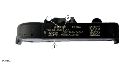
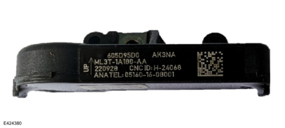
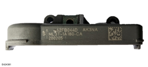
Engineering Part Number Description GL3T-1A180-GA 315 MHz Faraday - High Speed Valve GL3T-1A180-GB 315 MHz Faraday - High Speed Valve GL3T-1A180-HA 433 MHz Faraday GL3T-1A180-HB 433 MHz Faraday Identifying Correct Ford OE Sensor (ML3T / Potted Faraday) For A Particular Vehicle (Figures 28-29)
Figure 28
Figure 29
3 - ML3T-1A180-**
Engineering Part Number Description ML3T-1A180-AA 315 MHz Potted Faraday ML3T-1A180-CA 433 MHz Potted Faraday (Grey Enclosure) Identifying Correct Ford OE Sensor (F2GT / Faraday) For A Particular Vehicle (Figure 30)
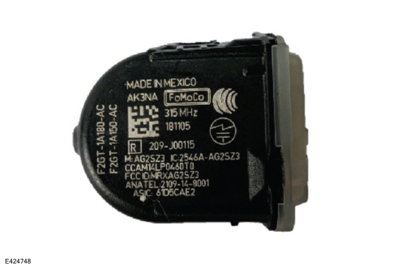
Figure 30
4 - F2GT-1A180-**
Engineering Part Number Description F2GT-1A180-AA 315 MHz Faraday - Low Speed Valve F2GT-1A180-AB 315 MHz Faraday - Low Speed Valve F2GT-1A180-AC 315 MHz Faraday - Low Speed Valve F2GT-1A180-AD 315 MHz Faraday - Low Speed Valve F2GT-1A180-AE 315 MHz Faraday - Low Speed Valve F2GT-1A180-EA 433 MHz Faraday - Low Speed Valve F2GT-1A180-EB 433 MHz Faraday - Low Speed Valve Identifying Correct Ford OE Sensor (HC3T / Faraday) For A Particular Vehicle (Figure 31)
Figure 31
5 - HC3T-1A180-**
Engineering Part Number Description HC3T-1A180-AA 315 MHz Faraday - High Speed Valve HC3T-1A180-AB 315 MHz Faraday - High Speed Valve HC3T-1A180-AC 315 MHz Faraday - High Speed Valve HC3T-1A180-AD 315 MHz Faraday - High Speed Valve HC3T-1A180-AE 315 MHz Faraday - High Speed Valve HC3T-1A180-GA 315 MHz Faraday - High Speed Valve HC3T-1A180-GB 315 MHz Faraday - High Speed Valve Identifying Correct Ford OE Sensor (FR3V / Bolt-On Faraday) For A Particular Vehicle (Figure 32)
Figure 32
6 - FR3V-1A180-**
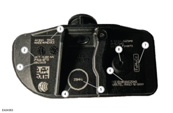
Engineering Part Number Description FR3V-1A180-AA 315 MHz Faraday - Bolt-On Valve FR3V-1A180-AB 315 MHz Faraday - Bolt-On Valve FR3V-1A180-AC 315 MHz Faraday - Bolt-On Valve FR3V-1A180-CC 433 MHz Faraday - Bolt-On Valve FR3V-1A180-GB 315 MHz Faraday - Bolt-On Valve E-Coated Washer FR3V-1A180-HB 433 MHz Faraday - Bolt-On Valve E-Coated Washer Identifying Correct Ford OE Sensor (JX7T / MHSSI) For A Particular Vehicle (Figure 33)
Figure 33
7 - JX7T-1A180-**
Engineering Part Number Description JX7T-1A180-AA 315 MHz MHSSI - High Speed Valve JX7T-1A180-EA 315 MHz MHSSI - Low Speed Valve Identifying Correct Ford OE Sensor (PR3T / Burnell) For A Particular Vehicle (Figure 34)
Figure 34
8 - PR3T-1A180-**
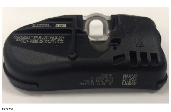
Engineering Part Number Description PR3T-1A180-AB 315 MHz Burnell - Low Speed Valve PR3T-1A180-CB 433 MHz Burnell - High Speed Valve PR3T-1A180-EB 315 MHz Burnell - Bolt-On Valve PR3T-1A180-GB 433 MHz Burnell - Bolt-On Valve PR3T-1A180-KB 433 MHz Burnell - Low Speed Valve #2 PR3T-1A180-MB 433 MHz Burnell - Low Speed Valve Identifying Correct Ford OE Sensor (PC3T / Steel Carcass) For A Particular Vehicle (Figures 35-36)
Figure 35
Figure 36
9 - PC3T-1A180-**
Engineering Part Number Description PC3T-1A180-CA 433 MHz Steel Carcass Production Steel Wheel Valve (Bent Brass) PC3T-1A180-GB 433 MHz Steel Carcass Production Alloy Wheel Valve Identifying Correct Ford OE Sensor For Trailer TPMS (Figure 37)
Figure 37
10 - HC3T-1A180-**
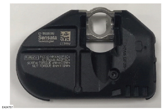
Engineering Part Number Description HC3T-1A180-CA 433 MHz Trailer Sensor HC3T-1A180-CB 433 MHz Trailer Sensor HC3T-1A180-CC 433 MHz Trailer Sensor Identifying Correct Ford OE Sensor For Steel Carcass Trailer TPMS (Figures 38-39)
Figure 38
Figure 39
11 - PC3T-1A180-**
Engineering Part Number Description PC3T-1A180-JB 433 MHz Trailer Steel Carcass Sensor TPMS Identification Chart (Figure 40)
The numbers in this chart identify the type of sensors for each vehicle program. The numbers are in the upper left corner of the tables in Figures 25-39.
Figure 40 - TPMS Identification Chart
Model 2015 2016 2017 2018 2019 2020 2021 2022 2023 2024 Aviator 7 7 7 8 Bronco 3 3 3 3 Bronco Sport 4 4 4 4 Continental 4 4 4 4 4 C-Max 1 1 Corsair 7 7 7 7 7 EcoSport 4 4 4 4 Edge 4 4 5 5 2, 5 2, 4 3, 4 3, 4 3, 4 3, 4 Escape 1 1 1 1 1 7 7 7 7 7 E-Series 1 1 1 1 1 2, 6 2, 6 2, 3 2, 3 2, 3 Expedition 1 1 1 2, 5 2, 5 2 2 2, 3 3 3 Explorer / Police Interceptor Utility 1 4 4 4 4 7 7 7 7 8 F-150 4 2 2 2 2 2 3 3 3 3 F-150 Lightning 3 3 3 3 F-150 Raptor 2 2 2 2 2 3 3 3 3 F-Super Duty 1 1 5, 6 2, 5, 6 2, 5, 6 2, 5, 6 2, 6 2, 3, 6 3, 6 3, 6 Fiesta 1 1 1 4 4 4 Flex 1 1 1 1 1 Focus 1 1 1 1 Ford GT * * * * * * Fusion 1 1 5 5 5 5 Maverick 4 4 4 4 MKC 1 1 1 5 5 MKS 1 1 MKT 1 1 1 1 1 MKX 4 4 2, 4 2, 4 MKZ 1 1 5 5 5 5 Mustang 4 4 4 4 4 4 4 4 4 4 Mustang Mach-E 4 4 4 Mustang SVT ** 6 6 6 6 6 6 6 6 6 Nautilus 2, 5 2, 4 3, 4 3, 4 3, 4 3, 4 Navigator 1 1 1 2, 5 2, 5 2 2 2, 3 3 3 Ranger 5 5 3 3 3 3 Taurus / Police Interceptor Sedan 1 1 1 1 1 Transit 1 1 1 1 1 6, 7 6, 7 6, 7 6, 7 6, 7 Transit Connect 1 1 1 4 4 4 4 4 4 Trailer TPMS Kit 10 10 10 10 10 10 10, 11 11
Figure 40 legend* Ford GT uses a specialized black anodized bolt-on valve. The part number prefix for this is HG7Z. ** Mustang SVT uses a bolt-on valve. The part number prefix for this is DR3V. TPMS Sensor Non-Warrantable Issues
With the variety of sensors that come equipped on Ford/Lincoln vehicles, make sure the sensor type is carefully identified and the correct mount and dismount procedure is used for each type of TPMS sensor. Damage to the TPMS sensor is identifiable with each part being reviewed prior to warranty approval. The sensor may not respond for a number of non-warrantable reasons that require the replacement of the sensor. They are:
• Damage due to improper tire mount and/or dismount procedure
• Damage due to being run on a flat or severely under-inflated tire
• Damage due to impact
• Damage due to improper removal of the valve stem
• Sensor replaced due to the use of a tire sealant
• Pressure port clogged due to the use of sealants or other materials (rubber, grease, balancing materials, etc.)
• Damage due to mounting on wheels not designed to accommodate TPMS sensors properly
Other Non-Warrantable Conditions:
• Wrong frequency parts
• Wrong sensor type (both Ford and non-Ford sensors)
• Over-repair (replacing the whole sensor vs replacing a valve)
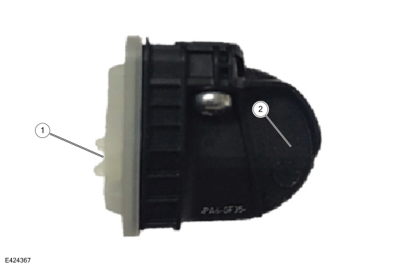
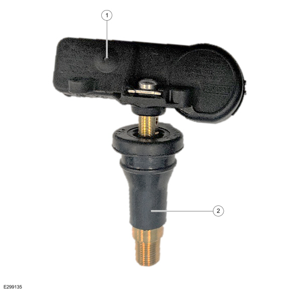
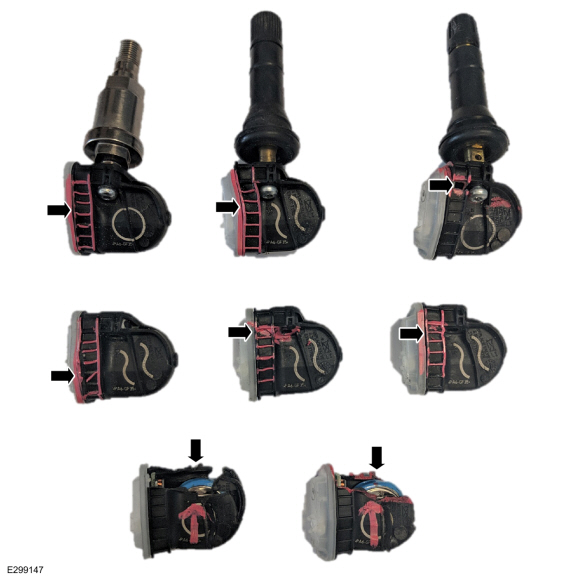
Good Part Examples (Figures 41-44)
Figure 41
Item Description 1 Undamaged valve stem
2 Undamaged ladder area/lid
3 Undamaged sensor body
Figure 42
Item Description 1 Correct Ford Part Number
2 Undamaged Sensor Body
Figure 43
Item Description 1 Pressure Port Not Obstructed
2 Undamaged Valve Stem
Figure 44
Item Description 1 Undamaged Valve Stem
2 Undamaged Potting
Non-Ford Part Examples (Chargebacks)
Different colors. North American units all use black parts. (Figures 45-46)
Figure 45
Figure 46
No Ford part number (Figures 47-48)
Figure 47
Figure 48
Different shapes.
NOTE: North American units all use either the Edison or the Faraday profile. (Figure 49)
Figure 49
Aftermarket Branding.
NOTE: This could include branding such as EzSensor, Redi, and Schrader (Figure 50)
Figure 50
Sensor Damage Examples (Chargebacks)
Damaged valve stems (Figures 51-54)
Figure 51
Figure 52
Figure 53
Figure 54
Damage to the sensor body (Figures 55-56)
Figure 55
Figure 56
Avoiding Chargebacks
Wrong Part Details: Things To Look For:
1) Does the sensor build date make sense for the model year of the vehicle? For example, if the sensor was built in 2019, it would not make sense to see this on a vehicle that is newer than the date on the sensor. It should be fairly close to the vehicle's production date.
2) Does the part number match what is listed in the catalog?
3) Is the part the correct frequency? Unless it is a trailer sensor the frequency for North American vehicles should be 315 MHz.
Wrong Part Returned: This is the most common chargeback when it comes to TPMS. A few ways to avoid being charged back for this can include:
1) Include the sensor ID, build date, and part number within the technician comments. This will make sure that the part attached to the 700 tag is the part that is returned.
2) Verify the correct sensor using the parts catalog or this document. Sending back an Edison sensor instead of a Faraday sensor will result in a chargeback and vice versa.
3) Include a second copy of the 700 tag in the shipping box/envelope if attaching to the outside package.
4) Do not return a sensor that was made in 2009 for a vehicle that was made in 2019, as an example. If the sensor is over a year old compared to the vehicle build date then it is highly likely it is the wrong part.
5) Do not send back non-Ford TPMS sensors or other Ford parts.
6) Do not send back 433 MHz sensors if the vehicle has over 1,000 miles. North American vehicles do not use this frequency (trailer TPMS does).
Sensor Damaged: This is the second most common chargeback:
1) The easiest way to avoid being charged back for this is to properly dismount the tire. Also making sure to remove the sensor from the valve stem before attempting to remove the valve stem.
2) If a sensor is damaged, and it is not caused by the plant, then do not send it back. Plant damage is easily determined upon review.
3) Do not send back a sensor if the valve stem was damaged.
4) Any defacing or intentional damaging of the part will result in a chargeback.
Over Repair: This is the third most common chargeback. Examples of this include:
1) Replacing the entire sensor kit for a leaky valve. Order the proper valve kit to replace the valve.
2) Replacing the entire sensor kit for a cracked or blemished wheel.
3) Replacing all 4 sensors due to a BCM or RTM issue.
4) Replacement BCMs do not have the TPMS IDs stored in them. Non-functional RTMs will cause TPMS faults.
© 2024 Ford Motor Company
All rights reserved.
NOTE: This information is not intended to replace or supersede any warranty, parts and service policy, workshop manual (WSM) procedures or technical training or wiring diagram information.
-
3
-
-
While I have not used one personally, I have read glowing descriptions on other Forums about the goodness of U-Haul auto transport trailers.
If you have -- or can rent -- a tow vehicle of appropriate capacity -- which U-Haul will verify prior to renting you the trailer -- then that may work for your trip to the Buckeye State.
Good luck!
-
2
-
-
Welcome to the Forum, theo wilkison !
If you are interested in the above-described discussion, it remains active at...
https://www.fordedgeforum.com/topic/29887-removing-side-roof-panels/
Good luck!
-
-
3
-


Do 2011 tail lights fit a 2010
in Glass, Lenses, Lighting, Mirrors, Sunroof (BAMR), Wipers
Posted · Edited by Haz
I normally wait until 100 views, because most Forum members are more experienced than I am.
(Just kidding about the former, but serious about the latter.)
2010 Edge Wiring Diagram and Park/Stop/Turn Connector Details
2011 Edge Wiring Diagram and Park/Stop/Turn Connector Details
Good luck!