


Haz
-
Posts
1,095 -
Joined
-
Last visited
-
Days Won
272
Content Type
Profiles
Forums
Gallery
Posts posted by Haz
-
-
SSM 52076 - 2019-2021 Edge/Nautilus - AWD - RDU Actuator Noise From The Rear Of The Vehicle When Approaching Vehicle Or Prior To Starting Engine
Some 2019-2021 Edge/Nautilus vehicles equipped with all wheel drive (AWD) may exhibit a noise from the rear of the vehicle while approaching the vehicle or prior to starting engine. This may be due to the rear drive unit (RDU) actuator learning process. Reprogram the software in the AWD module to minimize the noise using the latest software level of the appropriate Ford diagnostic scan tool. If no other concerns or symptoms are present, further diagnosis or repairs are not recommended. For claiming, use causal part 4000 and applicable labor operations in Section 10 of the Service Labor Time Standards (SLTS) Manual.
-
 3
3
-
-
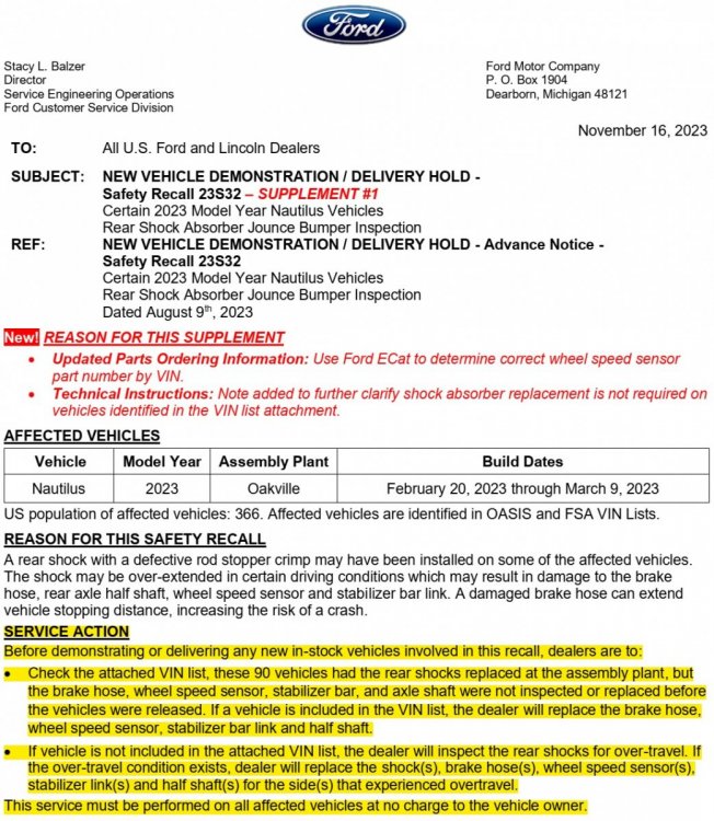
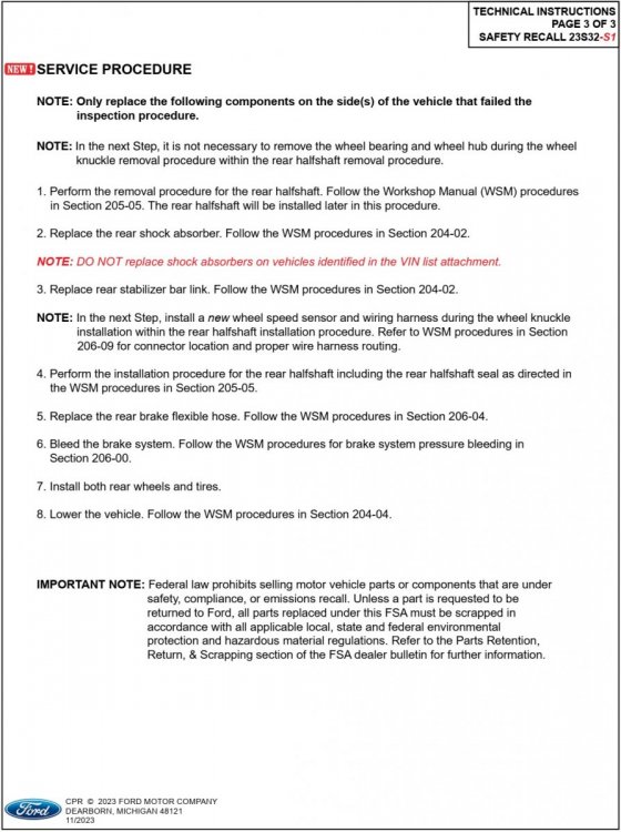
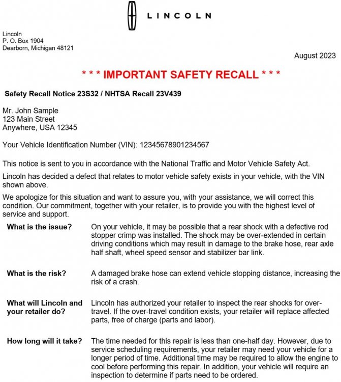
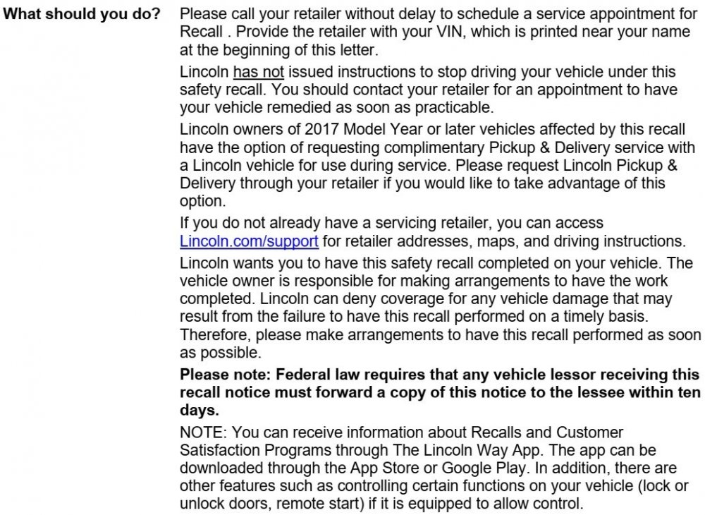
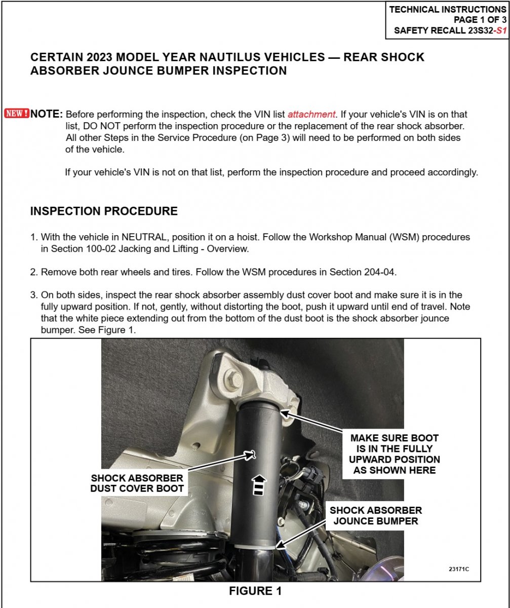
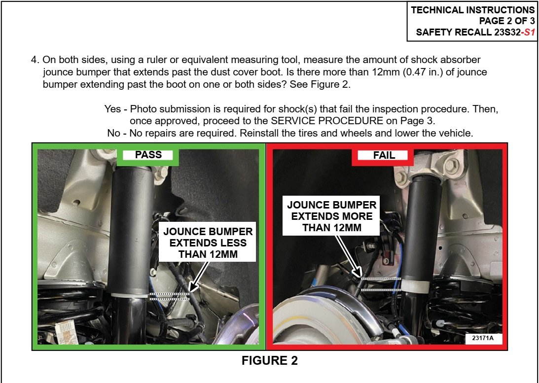
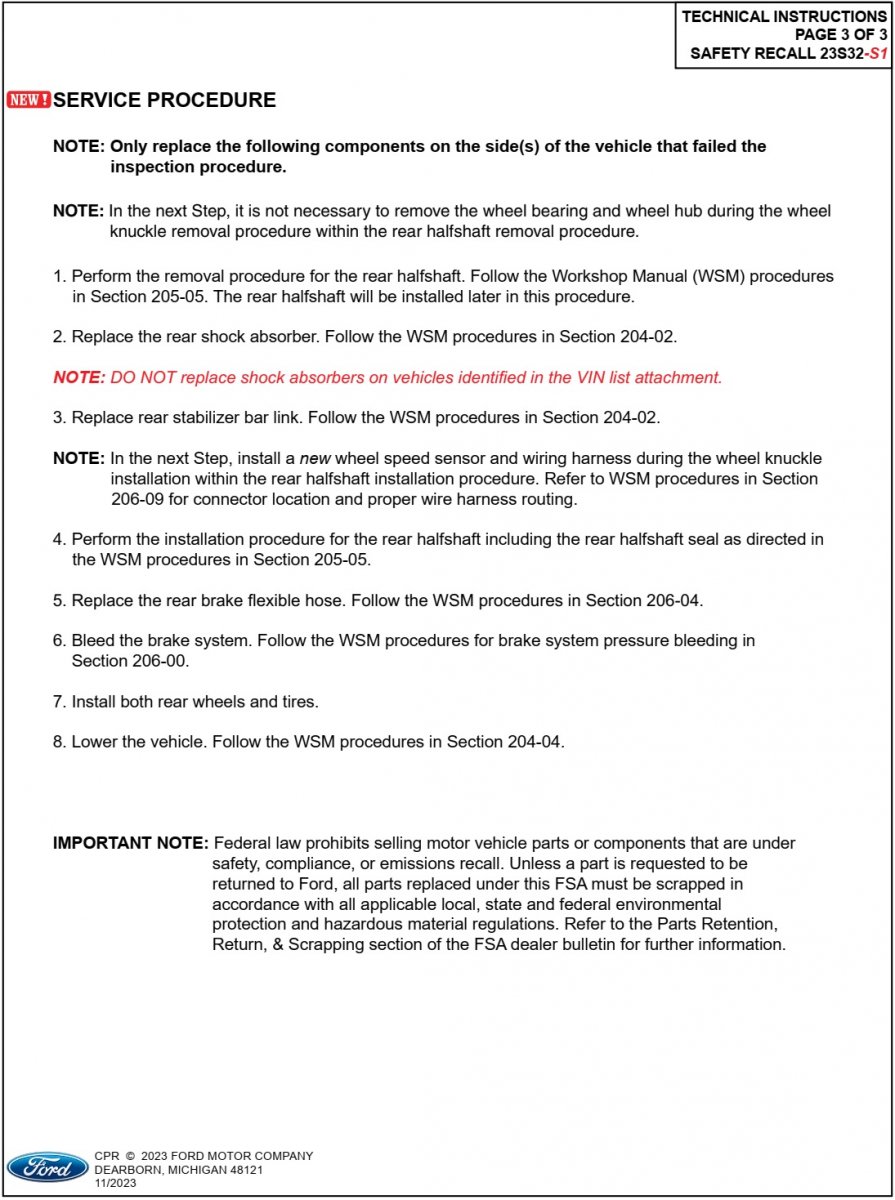
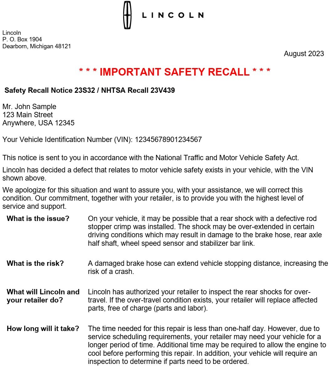
Dealers have received additional information regarding Safety Recall 23S32...


-
1
-
-
Document download link> TSB 23-2345 - Navigation Feature Unable To Change From Miles To Kilometers On SYNC 4 Equipped Vehicles.pdf
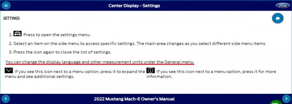
TECHNICAL SERVICE BULLETIN
Navigation Feature Unable To Change From Miles To Kilometers On SYNC 4 Equipped Vehicles23-2345
14 November 2023Model:
Ford2021-2023 BroncoBuilt on or before 18-Jul-20232023 Escape Built on or before 26-Jul-20232022-2023 Expedition 2022 Super Duty 2021-2023 F-150 Lincoln2021-2023 NautilusBuilt on or before 03-Apr-20232023 Corsair Built on or before 26-Jul-20232022-2023 Navigator Issue: Some 2021-2023 Ford and Lincoln vehicles equipped with SYNC 4 may exhibit the navigation feature in the center display screen only displaying imperial (feet and miles) units and not being able to change to metric (meters and kilometers) units. This may be due to the software level of the SYNC module (APIM). To correct this condition, follow the Service Procedure to update the APIM to the latest software level via a coordinated flash.
NOTE: The APIM software update that addresses the symptom listed in this article may have been sent via Ford Power-Up software updates delivered over-the-air (OTA) to connected vehicles that have automatic updates enabled through the center display screen. Enter the vehicle identification number (VIN) in Professional Technician System (PTS) and check the OTA Dashboard under the Connected Vehicle tab for OTA update history. If an update to the APIM has successfully completed recently and the customer is reporting the symptoms are no longer present, this article may not apply.
Action: Follow the Service Procedure to correct the condition on vehicles that meet all of the following criteria:
• One of the following vehicles:
- 2021-2023 Bronco built on or before 18-Jul-2023- 2021-2023 Nautilus built on or before 03-Apr-2023- 2023 Escape/Corsair built on or before 26-Jul-2023- 2022-2023 Expedition/Navigator- 2022 F-Super Duty- 2021-2023 F-150 (non-Lightning) vehicles• Equipped with SYNC 4
• Navigation feature in the center display screen only displaying imperial (feet and miles) units and not being able to change to metric (meters and kilometers) units
Parts
Parts To Inspect And Replace Only If Necessary
Service Part Number Quantity Description Unit of Issue Piece Quantity BAGM-94RH7-800 1 Battery (800 Amp) - Refer To The Parts Catalog For The VIN Specific Application 1 If Needed BAGM-48H6-760 1 Battery (760 Amp) - Refer To The Parts Catalog For The VIN Specific Application 1 If Needed BAGM-49H8 1 Battery (850 Amp) - Refer To The Parts Catalog For The VIN Specific Application 1 If Needed BXT-99RT4-A 1 Battery (470 Amp) - Refer To The Parts Catalog For The VIN Specific Application 1 If Needed BEF-48H6-A 1 Battery (700 Amp) - Refer To The Parts Catalog For The VIN Specific Application 1 If Needed BXT-94RH7-730 1 Battery (730 Amp) - Refer To The Parts Catalog For The VIN Specific Application 1 If Needed BXT-65-650 1 Battery (650 Amp) - Refer To The Parts Catalog For The VIN Specific Application 1 If Needed BXT-59-W 1 Battery (540 Amp) - Refer To The Parts Catalog For The VIN Specific Application 1 If Needed BXT-65-750 1 Battery (750 Amp) - Refer To The Parts Catalog For The VIN Specific Application 1 If Needed BXT-48H6-610 1 Battery (610 Amp) - Refer To The Parts Catalog For The VIN Specific Application 1 If Needed Quantity refers to the amount of the service part number required to repair the vehicle.
Unit of Issue refers to the number of individual pieces included in a service part number package.
Piece Quantity refers to the total number of individual pieces required to repair the vehicle.
As Needed indicates the amount of the part may vary and/or is not a whole number. Parts can be billed out as non-whole numbers, including less than 1.
If Needed indicates the part is not mandatory.
Labor Times
Description Operation No. Time 2021-2023 Various Vehicles: Check Battery State Of Charge And Reprogram The Appropriate Modules As Required By The Software Update And Service Procedure (Do Not Use With Any Other Labor Operations) MT232345 Actual Time Repair/Claim Coding
Causal Part: 14G371 Condition Code: 04 Service Procedure
NOTE: Ask the customer to bring their spare key fob to assist in the Ford Diagnosis and Repair System (FDRS) programming. The time required to complete this procedure will vary depending on several factors including the number of module software updates required, available internet bandwidth, universal serial bus (USB) flash drive variability, and the potential that controller area network (CAN) flashing (software update via the data link connector [DLC] with FDRS) may be required. It is recommended to connect to the internet with an ethernet cable and use a USB 3.0/3.1 capable flash drive when performing software updates.
1. Start an FDRS session and navigate to Toolbox tab > Datalogger > body control module (BCM) and select the BATT_SOC parameter identification (PID). Verify the PID reads 50% or higher. If state of charge (SOC) is less than 50%, charge the battery then navigate back to Toolbox tab > BCM > Reset Battery Monitor Sensor Learned Values application. Perform the battery monitor sensor (BMS) reset.
(1). If the battery is unable to achieve an 50% SOC then a new battery may be required. Use the Rotunda GRX-3590 or DCA-8000 testers to verify if replacement is required. If the battery is replaced, fully recharge the new battery. Then disconnect the Rotunda charger and perform a BMS reset using the FDRS scan tool.
2. Reconnect the battery charger and set it to maintain a vehicle voltage of 12.6 – 13.6 volts. A low battery state of charge while performing a software update to any module may result in a repeat Restart Required message in the vehicle center screen or a message on the FDRS saying Part Number Validation Failed or DID Validation Failed.
3. Are there any updates available for the gateway module A (GWM), APIM, or telematic control unit module (TCU)?
(1). Yes - proceed to Step 4.
(2). No - this article does not apply. Refer to Workshop Manual (WSM), Section 415-00.
4. Perform the Module Software Updating Procedures outlined below for the GWM, APIM, and TCU. Perform a network test after each software update using the latest software level of the FDRS scan tool. This will refresh the list of modules that have available software updates based current module software levels. Continue performing software updates until all available software updates for those modules are complete. If any error conditions are experienced during programming, refer to WSM Section 418-01A > General Procedures > Module Programming for the Error Condition Table.
Module Software Updating Procedure
NOTE: Depending on the current software level of the modules, all the following updates may not be required.
The following instructions apply when performing a software update on any of the following modules:
- GWM
- APIM
- TCU
NOTE: If the next update is not showing available, perform a network test and recheck availability.
NOTE: A 32GB or larger universal serial bus (USB) flash drive is required for the GWM, TCU and APIM software updates. USB 3.0 or higher is recommended for faster file transfer.
Make sure the USB flash drive being used is formatted correctly. To see the available drives, hold down the Windows icon keyboard key and press the E keyboard key. Right click on the USB flash drive and select Properties. If File System under the General tab is not exFAT, the drive must be formatted.
To format the USB flash drive:
• Right click on the USB flash drive
• Select Format, select exFAT for the File System
• Select Default Allocation Size for the Allocation Unit Size.
De-selecting Quick Format is not necessary and will result in a lengthier operation.
1. Using the FDRS, begin module programming by selecting the SW Updates tab. Follow all on-screen instructions carefully. Perform the next available update.
2. When prompted, connect the USB flash drive to the FDRS.
3. When prompted by the FDRS, safely remove/eject the USB flash drive from the FDRS and connect it to the USB media hub to install the software into the module. When the USB software update begins, the center display screen displays a message stating Do Not Remove USB. The update may take 10 minutes or longer to complete.
NOTE: It may take up to 5 minutes for the vehicle to recognize the USB flash drive.
4. When the pop-up stating Restart Required appears on the center display screen:
(1). Turn the ignition off.
(2). Wait for 10 minutes.
(3). Restart the vehicle (key-on vehicle running/ready). The update is still in progress at this time.
NOTE: It may take up to 5 minutes before the center display screen displays Update Successful pop up. After 5 minutes if Update Successful pop up is not shown on the center display screen, remove the USB and select yes on the FDRS Was the USB Update Successful prompt (FDRS verifies if the module software update was successfully installed on the module).
5. Once the pop up stating Update Successful appears in the center display screen, select Close, remove the USB flash drive from the USB media hub, and select Yes on FDRS indicating the update installed successfully. This initiates the remaining automated configuration steps and reports the module software part numbers and application software levels to the Ford online database. Failure to follow this step results in an inaccurate database as well as omitted, improperly installed, or improperly configured applications (features) such as navigation (if equipped). It is normal for the module to reset during this step.
© 2023 Ford Motor Company
All rights reserved.
NOTE: The information in Technical Service Bulletins is intended for use by trained, professional technicians with the knowledge, tools, and equipment to do the job properly and safely. It informs these technicians of conditions that may occur on some vehicles, or provides information that could assist in proper vehicle service. The procedures should not be performed by "do-it-yourselfers". Do not assume that a condition described affects your car or truck. Contact a Ford or Lincoln dealership to determine whether the Bulletin applies to your vehicle. Warranty Policy and Extended Service Plan documentation determine Warranty and/or Extended Service Plan coverage unless stated otherwise in the TSB article. The information in this Technical Service Bulletin (TSB) was current at the time of printing. Ford Motor Company reserves the right to supersede this information with updates. The most recent information is available through Ford Motor Company's on-line technical resources.
-
1
-
-
SSM 52064 - 2019-2021 Edge/Nautilus - AWD - Chatter/Shudder/Grind/Bind During Low Speed Turning Events
Some 2019-2021 Edge/Nautilus vehicles equipped with all-wheel drive (AWD) may exhibit a noise/vibration/chatter/shudder/grind/bind from the rear of the vehicle during low speed turning events. To correct the condition, reprogram the AWD module using the latest software level of the appropriate Ford diagnostic scan tool. For claiming use casual part RECAL and applicable labor times in Section 10 of the Service Labor Time Standards (SLTS) Manual.
-
2
-
-
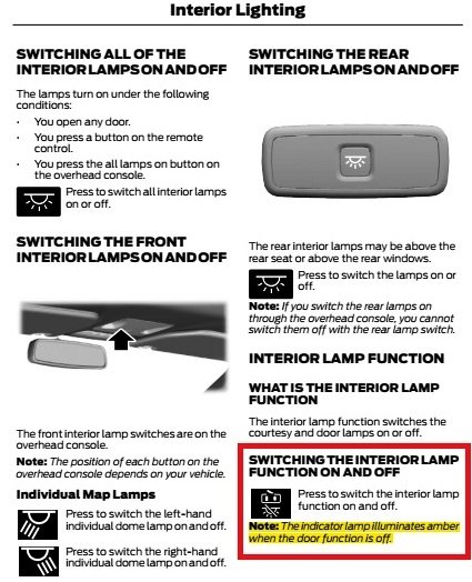
As @dabangsta describes, from page 103 of the 2024 Ford Edge Owner's Manual (PDF download link)...
Good luck!
-
1
-
-
Welcome to the Ford Edge Forum, amer fatayer!
There are many Mustang Mach-e discussion forums available to you... link to Web Search Listing.
But as long as you're here...
Document download links>
2022 Ford Mustang Mach-e Owner's Guide in English
2022 Ford Mustang Mach-e Quick Reference Guide in English
Good luck!
-
1
-
-
From PTS...
The Workshop Manual, Section 414-01, Description and Operation has been updated on all 2020 and later vehicles with a new folder called Battery Load Shed .
This folder has information on systems that are affected by battery state of charge during any vehicle system diagnostics.414-01 Battery, Mounting and Cables 2020 Edge Description and Operation Procedure revision date: 07/26/2023
Battery Load Shed
The main purpose of controlling electrical consumption with a load management strategy is to:
- Limit battery discharge
- Monitor the battery charge status
The alternator is not dimensioned to support all loads in all situations. In some situations energy has to be drawn from the battery. These are mainly during:
- engine idle
- cold climate with a lot of electrical heating functions active
- warm conditions with the engine cooling fan running
- large transient loads (i.e. EPAS )
During cold conditions, the charge acceptance of the battery is very low which increases the time needed to recharge the battery. This means that it can take up to several hours of driving before the battery is recharged.
The electrical consumption control is using Ignition_Status, Remote_Start_Status and EngineStateInternal in order to define the load management strategy during the different operating states of the vehicle.
The BCM is the primary module that is responsible for controlling the load management strategy. The BCM processes measurements of the system and uses the information for calculations and load prioritization
The strategy allows drain to occur from the battery. Load Management minimizes the drain by controlling the time and magnitude of the drain that can occur. The battery drain changes depending on the driving cycle and the types of loads the driver has activated, therefore, the BCM must be able to shut down or reduce the loads if necessary. The intent of the initial load shed stage, LSHED1, is to reduce electrical loads in a manner that is not noticed by the vehicle operator. During LSHED1, requests are sent in a prioritized order for the appropriate modules to begin shedding available loads. In order to prevent customer satisfaction issues, the loads are requested to reduce power consumption with minimum impact to the customer.
The second load shed event, LSHED2, occurs in two stages, SHED2_TRANS and SHED2_CONTIN. During operation of a vehicle equipped with large transient loads, there are transient peaks for current draw. The Load Management algorithm reacts to these spikes by using the SHED2_TRANS state. This state requires all non-critical loads to shed immediately, without customer indication, so that large transient loads can operate normally with little to no adverse impact to the customer. SHED2_CONTIN is a continuous deactivation of the loads to ensure the vehicle is able to re-start once the ignition is turned off. During SHED2_CONTIN, a message is displayed to the vehicle operator notifying them of the vehicle's charging system status.
Independent of load shed requests, the Load Management control can request boosts to the engine idle speed. Boosting the engine idle speed allows for increased output of the alternator to deliver more current to the battery. Idle speed increases are done through network IBoost messages.
The load shed charts provide a general overview of the features available on the vehicle based on the build options.
Load Shed Charts
Priority List Load Shedding 1
Priority List Load Shedding 1, Engine Running System Affected Battery State Of Charge (SOC) Battery Voltage Charging system at 95 % capacity Heated washer fluid Below 62% Below 11.6 Volts Heated steering wheel Smart trailer tow battery charge Heated and cooled seats Heated back glass, Heated mirrors Heated wind screen (windshield) Rear Aux blower Engine cooling fan Priority List Load Shedding 2
Priority List Load Shedding 2, Engine Running (which includes load shedding 1) System Affected Battery State Of Charge (SOC) Battery Voltage Charging system at 95 % capacity Energy management relay Below or equal to 50% Below 9 Volts Non-Chime related information 110 volt inverter 12 volt power points Ambient lighting Manual climate control blower (less FMVSS required for operation) NOTE: The electric booster heater has it's own Load Management strategy which includes idle boost request to the PCM and current limiting capabilities.
Electric booster heaterPriority List Load Shedding Engine Off
Priority List Load Shedding Engine Off System Affected Battery State Of Charge (SOC) Battery Voltage NOTE: Battery SOC threshold may increase slightly as the battery temperature gets colder (i.e. < 0°C /32°F)
- Ignition on/engine off for > 30 minutes and battery voltage <= to 12.8 Volts (Gasoline engines)
- Ignition on/engine off for > 30 minutes and battery voltage <= to 13.2 Volts (Electric vehicles)
- Ignition on/engine off for > 5 minutes and battery voltage <= to 12.8 Volts and battery SOC < 40% (Gasoline engines)
- Ignition on/engine off for > 5 minutes and battery voltage <= to 13.2 Volts and battery SOC < 40% (Electric vehicles)
Heated washer fluid Loads determined by the engine off timer by the BCM sets the load control status Heated steering wheel Smart trailer tow battery charge Heated and cooled seat (Rear Driver) - stage 3 Heated and cooled seat (Rear Passenger) - stage 3 Heated seat Only (Rear Driver) Heated seat Only (Rear Passenger) Heated wind screen (windshield) Dual automatic climate control front blower (less FMVSS required for operation) Manual climate control blower (less FMVSS required for operation) NOTE: Battery SOC threshold may increase slightly as the battery temperature gets colder (i.e. < 0°C /32°F)
- Ignition on/engine off for > 30 minutes and battery voltage <= to 12.8 Volts (Gasoline engines)
- Ignition on/engine off for > 30 minutes and battery voltage <= to 13.2 Volts (Electric vehicles)
- Ignition on/engine off for > 5 minutes and battery voltage <= to 12.8 Volts and battery SOC < 40% (Gasoline engines)
- Ignition on/engine off for > 5 minutes and battery voltage <= to 13.2 Volts and battery SOC < 40% (Electric vehicles)
Heated back glass, Heated mirrors Loads determined by the engine off timer by the BCM sets the load control status Split-screen Heated back glass, Heated mirrors Energy management relay Infotainment Electronic Finish Panel (less FMVSS required operation) 110 volt inverter 12 volt power points Ambient lighting
© Copyright 2023, Ford Motor Company.
Document download link> Battery Load Shed - Description and Operation - 2020 & Later Workshop Manuals.pdf
-
2
-
From the 2016 Edge Workshop Manual...
Document download links>
Quick Release Coupling - General Procedures - 2.0L EcoBoost - 2016 Edge Workshop Manual.pdf
Quick Release Coupling - General Procedures - 3.5L Duratec - 2016 Edge Workshop Manual.pdf
Good luck!
-
3
-
-
SSM 52051 - 2019-2023 Edge/Nautilus, 2022-2023 Maverick - AWD - Chatter/Shudder During Low Speed Turning Events
Some 2019-2023 Edge/Nautilus and 2022-2023 Maverick vehicles equipped with all wheel drive (AWD) may exhibit chatter/shudder during low speed turning events. This may be due to fluid contamination in the rear drive unit (RDU). Drain and refill the RDU, refer to Workshop Manual Section (WSM) 205-02. Drive for 5 miles (8 km) in stop and go conditions with right and left turns and re-evaluate. If the issue is still present, continue with normal WSM diagnostics. For claiming, use causal part 4000.
Supplemental information from 2019-2023 Edge-Nautilus Workshop Manual RDU Diagnostics and Testing document...
Axle Fluid Analysis
The appearance of yellow or green axle fluid in early mileage axles is a result of yellow marking compound used at the assembly plant to verify gear mesh contact pattern. The marking compound within the fluid will darken some over time. Appearance of milky fluid could be caused by water intrusion. Drain and refill the fluid and retest for normal operation.
Supplemental document download links> (Applicable to 2019-2023 Edge-Nautilus)
-
4
-
 1
1
-
-
-
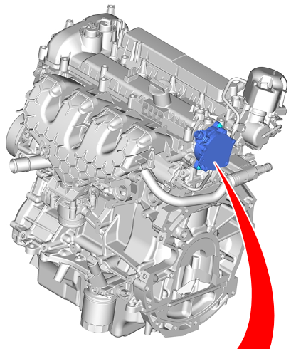
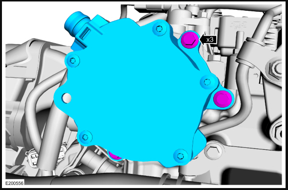
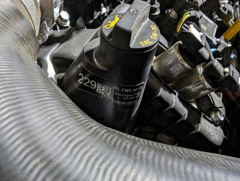
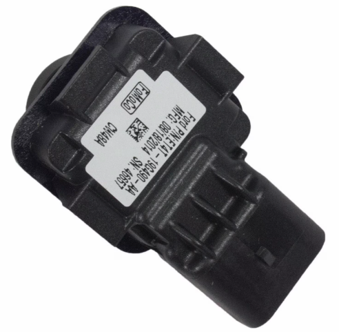
oskar27: The information you provide relates specifically to the Brake Vacuum Pump upon which the sticker is affixed...
For Engine Build information, refer to the Valve Cover Label shown in this post.
Good luck!
-
1
-
-
The following information from the Edge Workshop Manual may be helpful toward determining your vehicle's Engine Build Date...
Engine Code Information Label
The engine code information label, located on the LH valve cover, contains the following:
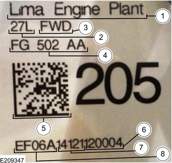
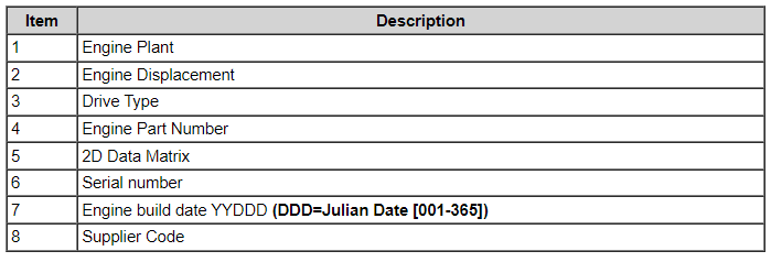
Item 6/7/8 data is also included as the Engine Trace Serial Number in the OASIS System's Vehicle Information Report, allowing verification of an engine as originally installed.
The label's appearance may vary by model year, but Build Date coding is consistent...
Good luck!
-
3
-
-
With appreciation to akirby for jogging my memory on the previously posted...
Good luck!
-
2
-
-
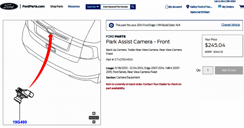
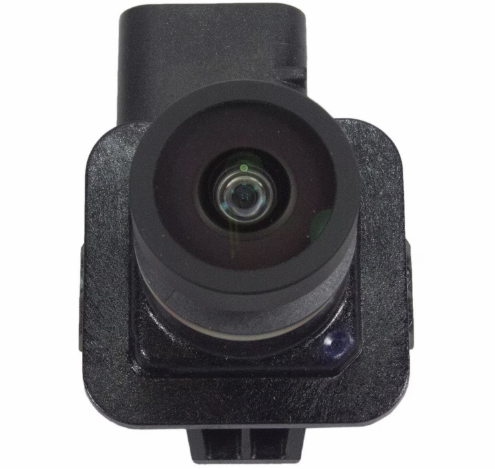
From the 2014 Edge Workshop Manual (placing your device cursor over underlined acronyms may yield full-word descriptions)...
Parking Aid Video
The rear video camera system consists of the following:
- Video camera (located in the liftgate)
- Accessory Protocol Interface Module (APIM) (If equipped with 8 in (203.2 mm) touchscreen)
- Front Display Interface Module (FDIM) (If equipped with 8 in (203.2 mm) touchscreen)
- FCDIM (If equipped with 4.2 in (106.68 mm) display)
- Instrument Panel Cluster (IPC)
- Body Control Module (BCM)
The video camera system visually aids the driver while reversing or reverse parking the vehicle. Fixed guidelines are displayed on the video image to assist the driver in backing into a parking space or aligning the vehicle with other objects while reversing.
On vehicles equipped with the 8 in (203.2 mm) touchscreen, the video camera system is equipped with the following optional features:
- Fixed guidelines — this feature assists the driver with backing into a parking space or aligning the vehicle with an object.
- Visual park aid alert — this feature assists the driver to visually see the object causing the parking aid system to sound.
- Manual zoom — this feature assists the driver with connecting or towing a trailer allowing the driver to manually zoom closer to an object behind the vehicle.
- Video camera delay — this feature allows the driver to see the image behind the vehicle after the vehicle is shifted out of reverse. The image will not be displayed if the vehicle is shifted into park.
The features are controlled though the FDIM .
Parking Aid Video - Principles of Operation
NOTE: Close the liftgate for correct operation of the video camera system.
The rear video camera system is active with the ignition in run and the transaxle selector in the REVERSE (R) position. The video camera receives commands and sends status over a dedicated Local Interconnect Network (LIN) to the Body Control Module (BCM) . The video camera sends a video signal to the Accessory Protocol Interface Module (APIM) (vehicles equipped with a 8 in (203.2 mm) touchscreen) or the FCDIM (vehicles equipped with a 4.2 in (106.68 mm) display) on a pair of shielded video circuits. The APIM sends the video signal to the Front Display Interface Module (FDIM) (mounted to the APIM ) which displays the video image of the area behind the vehicle.
For vehicles equipped with a 8 in (203.2 mm) touchscreen, the video camera system has 4 video features that are controlled in the FDIM . The features are:
- Fixed guidelines
- Visual park aid alert
- Manual zoom
- Video camera delay
NOTE: Vehicles equipped with a 4.2 in (106.68 mm) display do not have any features that can be configured by the driver. The system displays fixed guidelines that cannot be turned off.
For each one of these system features except the camera delay feature, the APIM sends a network message requesting the system feature to the Instrument Panel Cluster (IPC) via the High Speed Controller Area Network (HS-CAN) . The IPC sends the message to the BCM over the HS-CAN . The BCM sends the message to the video camera over the LIN . The LIN is a dedicated single wire communication line that sends and receives network messages from the BCM to the video camera. The video camera delay feature is controlled with in the APIM .
The messages sent from the BCM to the video camera are:
- transmission selector (PRNDL) status
- liftgate ajar status
- camera configuration data
- display manual zoom request
- parking aid audible warning status
- parking aid sensor distance to object data
The messages sent from the video camera to the BCM are:
- camera status
- display zoom status
- camera part number data
- visual park aid alert status
- fixed guideline status
All of the video camera features are enabled and disabled within the FDIM menu screen.
The video camera fixed guidelines feature displays guidelines on top of the video image to assist the driver with alignment of the vehicle. A dashed line on the displayed image represents the center of the vehicle and 3 color-coded lines (red, yellow, green) identify different zones between the rear of the vehicle and objects.
NOTE: The color-coded lines cannot indicate accurate or consistent distances between objects located behind the vehicle and at the rear of the vehicle. This normal condition is due to variances in vehicle ride height, including, but not limited to, vehicle loading.
The video camera delay feature keeps the image displayed on the FDIM until the vehicle reaches 8 km/h (5 mph) when the vehicle is shifted out of reverse or if any button on the FDIM is pressed.
The visual park aid alert feature utilizes the 4 parking aid sensor inputs from the Parking Aid Module (PAM) and the video camera image. When the transaxle selector is in the reverse position and an object is detected in the path of the parking aid sensor, a network message of the distance from the parking aid sensor to the object is sent from the PAM to the BCM over the HS-CAN . The BCM networks the parking aid sensor message to the video camera over the LIN . The visual alerts are red, yellow or green and appear as highlights on top of the displayed image to indicate in which zone the object is detected. The highlighted visual alerts are still operational if the parking aid system is disabled within the IPC and the visual alert feature is enabled.
The manual zoom feature is controlled by the video camera. The manual zoom feature has 3 zoom levels that are only active when the vehicle is in reverse. If the manual zoom feature is enabled and the vehicle is shifted out of reverse the manual zoom feature is disabled. The manual zoom feature must be re-enabled the next time the vehicle is shifted into reverse. When the FDIM requests the video image to be zoomed in or out, the APIM sends a zoom request network message to the IPC . The IPC sends the message to the BCM , which sends the zoom request message to the video camera over the LIN . The video image sent by the video camera is then digitally zoomed in or out.
Video Camera - Removal and Installation
Edge
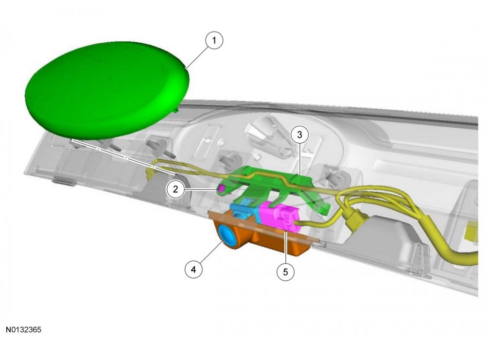
Removal
Edge
- Remove the rear liftgate applique. For additional information, refer to Section 501-08.
- Carefully remove the name plate from the rear liftgate applique and discard.
-
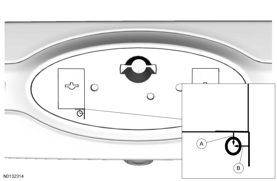
Drill a 6.35 mm (0.25 in) hole through the rear lift gate applique as indicated.
- A: measure down 3.175 mm (0.125 in) from the left side embossed edge.
- B: measure over 6.35 mm (0.25 in) from the left side embossed edge.

- Loosen the rear video camera bracket screw (T-20) through the access hole.
-
Remove the rear video camera bracket and the rear video camera.
- Disconnect the electrical connector.
Installation
Edge
-
Install the rear video camera and install the rear video camera bracket.
- Connect the electrical connector.
- Tighten the rear video camera bracket screw through the access hole.
- Cut a piece of mylar tape (19E523) 12.7 mm (0.5 in) long and cover the access hole.
- Install a new name plate onto the rear liftgate applique.
- Install the rear liftgate applique. For additional information, refer to Section 501-08.
-
NOTE: If the camera was replaced, the rear video camera guidelines will not display if the rear video camera is not configured.
Configure the rear video camera following the instructions on the scan tool.
© Copyright 2023, Ford Motor Company.
Document download links>
Liftgate Applique - Removal and Installation - 2014 Edge Workshop Manual.pdf
Liftgate Trim Panel - Removal and Installation - 2014 Edge Workshop Manual.pdf
Good luck!
-
3
-
Omar302: Good catch on the absent referred-to illustration!
I have edited and revised my original post.
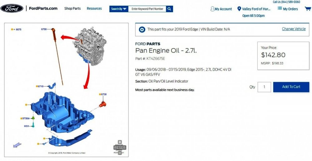
The originally released TSB 23-2338 lacked imagery, however, I checked the Professional Technician System website today and the missing images are now included, which clarifies the 'new' oil pan and preformed perimeter gasket.
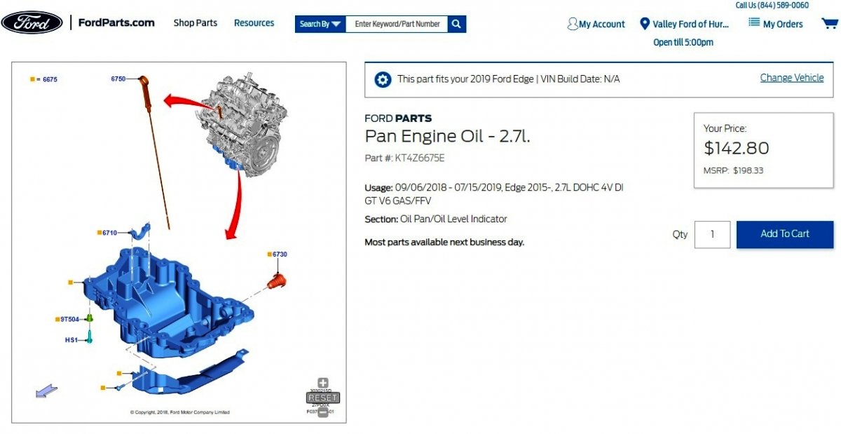
I say 'new', because I find the KT4Z-6675-E oil pan part number on several online sites associated with 2019 Edge-Nautilus & 2019-2023 F-150 2.7L EcoBoost installations, as well as the second image in the TSB comes straight from the Oil Pan Removal and Installation procedure in the 2019-2024 Edge-Nautilus & 2019-2023 F-150 Workshop Manuals.
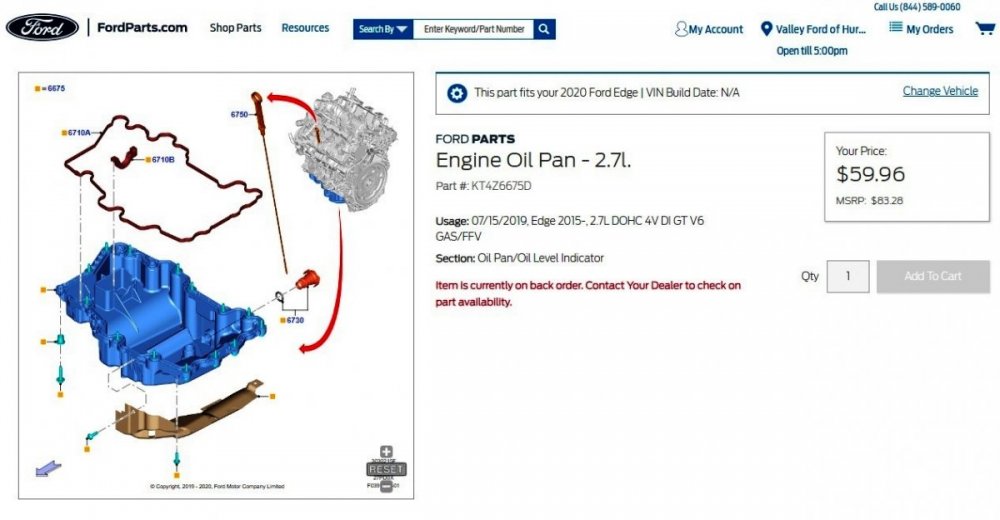
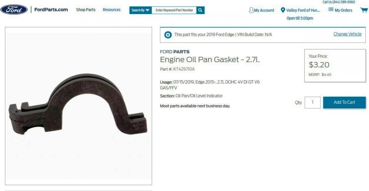
Ford's online parts-selling site includes this page for KT4Z6675E, which lacks any preformed perimeter in the illustration, and identifies the oil pan as fitting 2019 Edge & Nautilus, so FordParts is not quite ready for Prime Time on this...
Link to this FordParts webpage
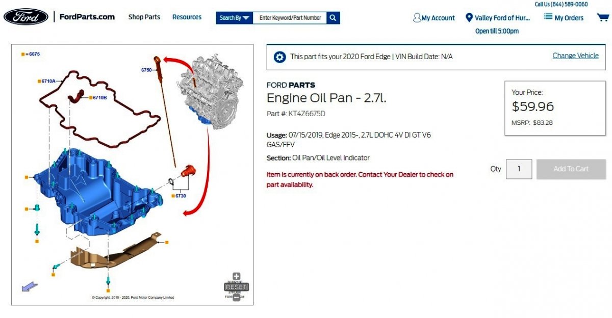
FordParts' webpage for the KT4Z6675D Oil Pan provides the previously expected illustration and indicates this part fits 2019-2024 Edge...
Link to this FordParts webpage
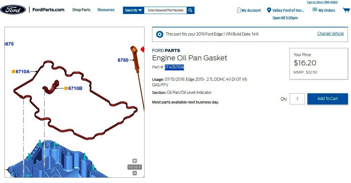
FordParts informs on this associated JT4Z6710A preformed perimeter Oil Pan Gasket, described as fitting 2019-2024 Ford Edge, 2019-2024 F-150-Lobo, 2021-2024 Bronco, and 2024 Ranger...
Link to this FordParts webpage

...and on the associated KT4Z6710B internal Oil Pan Gasket, described as fitting 2019 Lincoln Nautilus and 2019-2024 Ford Edge...
Link to this FordParts webpage

The following 2019 Edge Workshop Manual section may be a useful supplement to TSB 23-2338...
Document download link> Oil Pan - Removal and Installation - 2.7L EcoBoost - 2019 Edge Workshop Manual.pdf
bscott99: If you do not have any Ford/FordProtect Extended Service Plan (ESP) and your Edge's Powertrain Warranty expired at 5 Years/60,000 miles, but your Edge has received two replacement Oil Pans, then it is worth seeking coverage for the TSB 23-2338 Service on the basis of those prior warranty-covered (?) replacements under the Service Parts Warranty, especially if its 2-year timeframe fits...
Document download link> Ford-Motorcraft Service Parts Limited Warranty Summary - June 2023.pdf
Good luck!
-
3
-
-
This TSB 22-2181 has been superceded by TSB 23-2338 - 2015-2017 Edge 2.7L EcoBoost, 2016-2017 MKX 2.7L EcoBoost + Other Models - Oil Pan Leaking on 10-30-2023.
Good luck!
-
3
-
-
Document download link (corrected document)> TSB 23-2338 - 2.7L-3.0L EcoBoost - Oil Pan Leaking - 10-30-2023.pdf
TECHNICAL SERVICE BULLETIN
2.7L/3.0L EcoBoost - Oil Pan Leaking23-2338
30 October 2023This bulletin supersedes 22-2181.
Model:
Ford2015-2017 EdgeEngine: 2.7L EcoBoost2017 Fusion Engine: 2.7L EcoBoostLincoln2017 ContinentalEngine: 2.7L EcoBoostEngine: 3.0L EcoBoost2016-2017 MKX Engine: 2.7L EcoBoost2017 MKZ Engine: 3.0L EcoBoostSummary
This article supersedes TSB 22-2181 to update the Service Procedure and Part List.
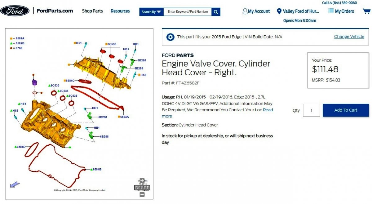
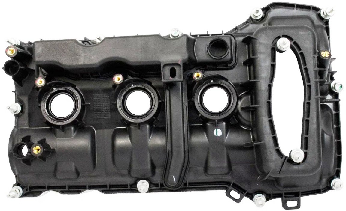
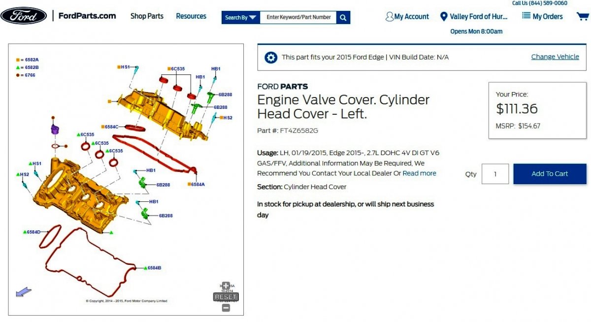
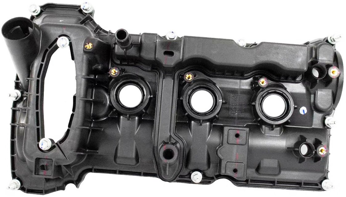
Issue: Some 2015-2017 Edge, 2016-2017 MKX, 2017 Fusion/MKZ/Continental vehicles equipped with a 2.7L EcoBoost or 3.0L EcoBoost engine may exhibit an oil leak from the engine oil pan RTV seal. This may be due to a lack of RTV adhesion. To correct the condition, follow the Service Procedure to replace the valve covers and replace the factory oil pan with a press in place gasket style oil pan.
Action: Follow the Service Procedure to correct the condition on vehicles that meet all of the following criteria:
• One of the following vehicles:
- 2015-2017 Edge- 2016-2017 MKX- 2017 Continental/Fusion/MKZ• 2.7L/3.0L Engine
• Oil leak from the oil pan RTV seal
Parts
Service Part Number Quantity Description Unit of Issue Piece Quantity Note 9W7Z-19B596-A 1 Seal Kit - A/C Compressor Gasket And O-Ring, 1/2 Inch (Edge/MKX) DL3Z-19B596-B 1 Seal Kit - A/C Compressor Gasket And O-Ring, 5/8 Inch (Continental 2.7L) HL3Z-19B596-A 1 Seal Kit - A/C O-Rings - 3/4 Inch, 1/2 Inch, 5/8 Inch And 3/8 Inch (Fusion/MKZ And Continental 3.0L) DS7Z-19B596-A 1 Seal Kit - A/C Compressor Gaskets 8 mm, 1/2 Inch, 5/8 Inch (All Models) KT4Z-6675-E 1 Oil Pan 1 1 Oil pan is different than the original part KU2Z-6731-A 1 Oil Filter Element And O-Ring Seals 1 1 O-ring seals are only available as an assembly with the oil filter W714265-S442 1 Left Catalytic Converter Nuts 4 2 FT4Z-6626-A 1 Oil Pump Seal 1 1 BL3Z-9450-A 1 Catalytic Converter Gasket 1 1 FT4Z-6582-F 1 Right Valve Cover 1 1 FT4Z-6582-G 1 Left Valve Cover 1 1 YN-33-A As Needed R-1234yf Refrigerant (All Markets Except Canada) HS7Z-19B519-BA As Needed R-1234yf Refrigerant (Canada Only) YN-35 As Needed Refrigerant Oil ZC-30-A As Needed Motorcraft® Gasket Remover TA-357 As Needed Motorcraft® High Performance Engine RTV Silicone XO- 5W30-Q1SP As Needed Motorcraft® SAE 5W-30 Synthetic Blend Motor Oil (All Markets Except Canada) CXO-5W30-LSP6 As Needed Motorcraft® SAE 5W-30 Super Premium Motor Oil (Canada Only) PM-4-A As Needed Motorcraft® Metal Brake Parts Cleaner (Compliant With Low Volatile Organic Compound Requirements As Required In Some USA States) PM-4-B As Needed Motorcraft® Metal Brake Parts Cleaner (Not Compliant With Volatile Organic Compound Requirements) VC-13-G As Needed Motorcraft® Yellow Concentrated Antifreeze/Coolant (All Markets Except Canada) CVC-13-G As Needed Motorcraft® Yellow Concentrated Antifreeze/Coolant (Canada Only) Parts
Parts To Inspect And Replace Only If Necessary
Service Part Number Quantity Description Note 1X4Z-9E936-AA If Needed Coil Boot (Fusion 2.7L) FU7Z-12A402-A If Needed Coil Boot (MKX 2.7L) FT4Z-6A832-C If Needed Oil Filter And Cap Assembly Kit Oil cap is only available as an assembly with the oil filter Quantity refers to the amount of the service part number package(s) required to repair the vehicle.
Unit of Issue refers to the number of individual pieces included in a service part number package.
Piece Quantity refers to the total number of individual pieces required to repair the vehicle.
As Needed indicates the amount of the part may vary and/or is not a whole number. Parts can be billed out as non-whole numbers, including less than 1.
If Needed indicates the part is not mandatory.
Warranty Status: Eligible under provisions of New Vehicle Limited Warranty (NVLW)/Service Part Warranty (SPW)/Special Service Part (SSP)/Extended Service Plan (ESP) coverage. Limits/policies/prior approvals are not altered by a TSB. NVLW/SPW/SSP/ESP coverage limits are determined by the identified causal part and verified using the OASIS part coverage tool.
Labor Times
Description Operation No. Time 2017 Continental 2.7L/3.0L EcoBoost: Inspect And Replace The Engine Oil Pan (Do Not Use With Any Other Labor Operations) 232338A 2.9 Hrs. 2017 Continental 2.7L/3.0L EcoBoost: Inspect And Replace Both Valve Covers And The Engine Oil Pan (Do Not Use With Any Other Labor Operations) 232338B 7.2 Hrs. 2015-2017 Edge, 2016-2017 MKX 2.7L EcoBoost: Inspect And Replace The Engine Oil Pan (Do Not Use With Any Other Labor Operations) 232338C 3.0 Hrs. 2015-2017 Edge, 2016-2017 MKX 2.7L EcoBoost: Inspect And Replace Both Valve Covers And The Engine Oil Pan (Do Not Use With Any Other Labor Operations) 232338D 7.6 Hrs. 2017 Fusion 2.7L EcoBoost: Inspect And Replace The Engine Oil Pan (Do Not Use With Any Labor Operations Outside Of This Article) 232338E 3.1 Hrs. 2017 Fusion 2.7L EcoBoost: Inspect And Replace Both Valve Covers And The Engine Oil Pan (Do Not Use With Any Other Labor Operations) 232338F 7.4 Hrs. 2017 MKZ 3.0L EcoBoost: Inspect And Replace The Engine Oil Pan (Do Not Use With Any Labor Operations Outside Of This Article) 232338G 3.1 Hrs. 2017 MKZ 3.0L EcoBoost: Inspect And Replace Both Valve Covers And The Engine Oil Pan (Do Not Use With Any Other Labor Operations) 232338H 8.1 Hrs. Repair/Claim Coding
Causal Part: 6675 Condition Code: D8 Service Procedure
NOTE: There are internal positive crankcase ventilation (PCV) system check valves built into some oil pans and valve covers. Follow the Service Procedure to make sure replacement parts are properly chosen to maintain an operable PCV system.
1. Inspect the valve cover design around the ignition coils on both sides. Does the coil location have the extended plastic protective ribbing as shown in red? (Figure 1)
Figure 1
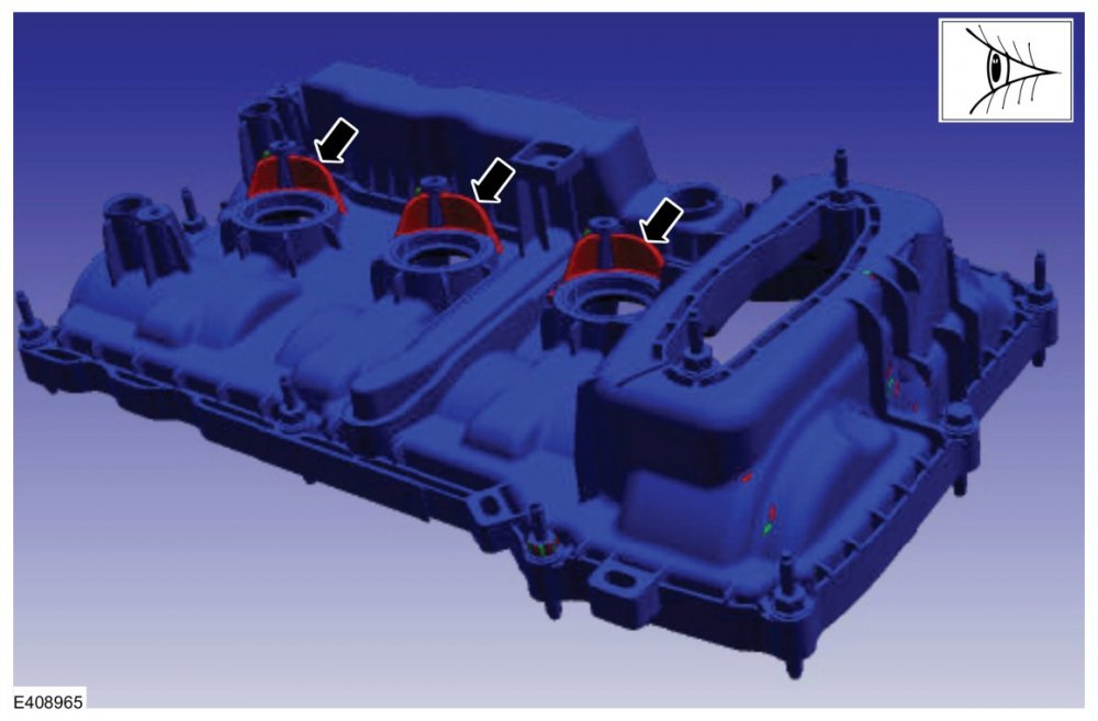
(1). Yes - proceed to Step 3.
(2). No - proceed to Step 2.
2. Replace both valve covers. Refer to Workshop Manual (WSM), Section 303-01, Removal and Installation > Valve Cover LH and Valve Cover RH. Proceed to Step 3.
3. Remove and discard the oil pan and oil pump seal. Refer to WSM, Section 303-01, Removal and Installation > Oil Pan.
4. Clean and prepare the engine sealing surface. Refer to WSM, Section 303-00 General Procedures.
5. Install the new oil pump seal. Refer to WSM, Section 303-01, Removal and Installation > Oil Pan.
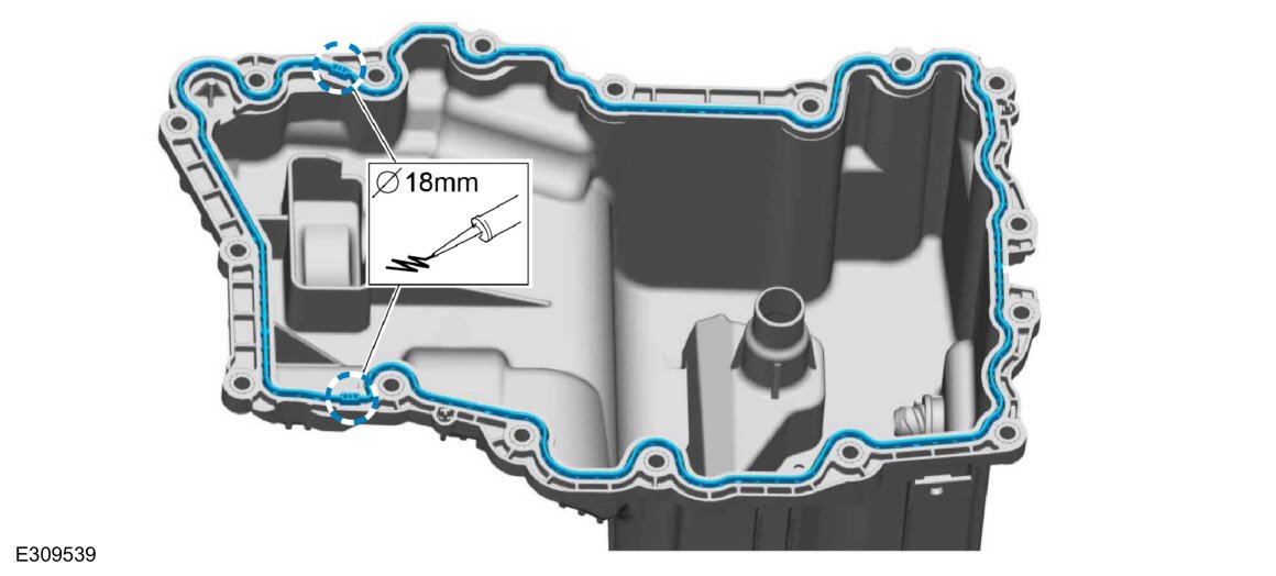
6. Apply a 18 mm (0.708 in.) bead of Motorcraft® High Performance Engine RTV Silicone to the oil pan where the front cover-to-cylinder block joint areas contact. (Figure 2)
Figure 2

NOTE: The new oil pan does not require the use of Motorcraft® High Performance Engine RTV Silicone in any other location.
7. Verify the correct orientation of the new press in place gasket and install the new oil pan. Refer to the WSM, Section 303-01, Removal and Installation > Oil Pan.
© 2023 Ford Motor Company
All rights reserved.
NOTE: The information in Technical Service Bulletins is intended for use by trained, professional technicians with the knowledge, tools, and equipment to do the job properly and safely. It informs these technicians of conditions that may occur on some vehicles, or provides information that could assist in proper vehicle service. The procedures should not be performed by "do-it-yourselfers". Do not assume that a condition described affects your car or truck. Contact a Ford or Lincoln dealership to determine whether the Bulletin applies to your vehicle. Warranty Policy and Extended Service Plan documentation determine Warranty and/or Extended Service Plan coverage unless stated otherwise in the TSB article. The information in this Technical Service Bulletin (TSB) was current at the time of printing. Ford Motor Company reserves the right to supersede this information with updates. The most recent information is available through Ford Motor Company's on-line technical resources.
-
5
-
-
Welcome to the Forum, Tor22 !
On 6/7/2022 at 4:29 PM, Haz said:Many gauge cluster warnings are low-voltage triggered, and most codes will clear when subsequent key cycles serve up normal voltage.
Have the battery tested -- probably a bad cell or bad cells.
Good luck!
-
Ford has established a download link to a new document which lists the latest SYNC 4 versions for all SYNC 4 equipped Ford/Lincoln models. by Model Year...
Document download link> SNYC 4 Latest Software Level
GENERAL SERVICE BULLETIN
Determining Latest SYNC 4 Software Level23-7146
25 October 2023Summary
This article will provide information on determining the latest level of SYNC 4 software due to FDRS limitations that may not expose available software updates and to make sure a complete update has been performed before returning the vehicle to the customer.
Service Information
In-vehicle method
NOTE: In some cases, other modules will need to be updated or updated multiple times before the latest SYNC 4 software is obtained. Always follow the directions in a TSB for the vehicle and model year completely to obtain the latest level of SYNC 4 software.
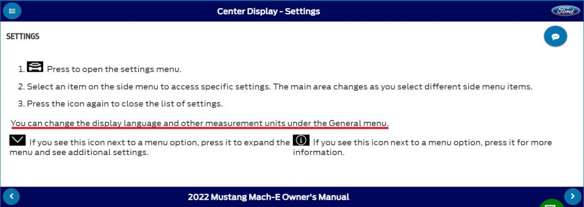
• While SYNC is powered up with ignition in run or accessory, go to the Settings selection on the center display screen.
- Refer to the Owner's Manual if Settings cannot be found.• Go to General Settings.
• Select About SYNC.
• Find the SYNC 4 Software Version followed by a number structure such as 4.0.*****. (*=numbers) Compare that version to the latest version located in this link: SNYC 4 Latest Software Level.
• If the version in the vehicle is lower than the number in the document, then follow the applicable TSB or SSM to update the software.
Referring to PTS method
NOTE: In some cases other modules will need to be updated or updated multiple times before the latest SYNC 4 software is obtained. Always follow the directions in a TSB for the vehicle and model year completely to obtain the latest level of SYNC 4 software.
• Go to the PTS website.
• Under the Vehicle ID tab, select By VIN enter the VIN number and select Go.
• When the system loads, highlight the Diagnostics tab and scroll down and select SYNC. Review the part number or version located next to the CIP and compare that to the latest version located in this link: SNYC 4 Latest Software Level.
• If the version in the vehicle is lower than the number in the document, follow the applicable TSB or SSM to update the software.
© 2023 Ford Motor Company
All rights reserved.
NOTE: This information is not intended to replace or supersede any warranty, parts and service policy, workshop manual (WSM) procedures or technical training or wiring diagram information.
-
2
-
1
-
-
From the 2019 Edge Workshop Manual (placing your device cursor over underlined acronyms should yield the full word description)...
High Beams
The SCCM monitors the LH steering column multifunction switch for a high beam request. When the LH steering column multifunction switch is in the HIGH BEAMS position, the SCCM sends a message over the HS-CAN2 to the GWM , then the GWM sends the message to the BCM over the HS-CAN1 .
When the low beams are on and the BCM receives a request for high beams, the low beam Light Emitting Diodes (LEDs) remains powered on and the high beam Light Emitting Diodes (LEDs) is also activated. This changes the headlamp beam pattern to illuminate a greater distance.
The BCM also provides Field Effect Transistor (FET) protection of the high beam output circuits. When an excessive current draw is detected, the BCM disables the affected circuit driver.
For additional information on BCM Field Effect Transistor (FET) protection,
Refer to: Module Controlled Functions - System Operation and Component Description (419-10 Multifunction Electronic Modules, Description and Operation).(Download link below)Headlamps (edited to provide high series info)
For high series headlamps, the LED headlamp system consists of a non-replaceable low and high beam Light Emitting Diodes (LEDs) that are focused through a single projector lens and additional high beam Light Emitting Diodes (LEDs) that are focused through a separate smaller lens inboard of the main lens.
If the LH steering column multifunction switch is pushed into the high beam position, the high beam Light Emitting Diodes (LEDs) illuminate until the LH steering column multifunction switch is returned to the center position.
The mid and high series headlamps may be equipped with automatic headlamp leveling. The headlamp beam height is automatically adjusted according to vehicle load, speed, acceleration and braking. Automatic headlamp leveling is activated when the headlamp switch is in the HEADLAMPS or AUTOLAMPS position.
The high series headlamps are equipped with adaptive front lighting. Depending on the inputs received (steering wheel angle and vehicle speed for example), the adaptive front lighting module can command the angle at which the headlamps are aimed (left or right) to improve nighttime visibility around curves. Adaptive front lighting is only activated when the headlamp switch is in the AUTOLAMPS position.
The following documents provide Headlamp system information, including Diagnostic Trouble Code (DTC) charts, wiring diagrams, connector details, and diagnostic Pinpoint Test 'B' for addressing the issue of one-or-both inoperative High Beam(s)...
Document download links>
Exterior Lighting - Overview - 2019 Edge Workshop Manual.pdf
Exterior Lighting - System Operation and Component Description - 2019 Edge Workshop Manual.pdf
Headlamps - Diagnosis and Testing - DTC Charts - 2019 Edge Workshop Manual.pdf
Headlamps, Left Hand - Wiring Diagram - 2019 Edge.pdf
HEADLAMP ASSEMBLY LH - Connector C1284 Details - 2019 Edge.pdf
Headlamps, Right Hand - Wiring Diagram - 2019 Edge.pdf
HEADLAMP ASSEMBLY RH - Connector C1285 Details - 2019 Edge.pdf
Headlamps Control Module - Wiring Diagram - 2019 Edge.pdf
HEADLAMP CONTROL MODULE (HCM) - Connector C2129 Details - 2019 Edge.pdf
Headlamp Control Module (HCM) - Removal and Installation - 2019 Edge Workshop Manual.pdf
BODY CONTROL MODULE (BCM) - Connector C2280B Details - 2019 Edge.pdf
Steering Column Control Module - Wiring Diagram - 2019 Edge.pdf
STEERING COLUMN CONTROL MODULE (SCCM) - Connector C226A Details - 2019 Edge.pdf
STEERING COLUMN CONTROL MODULE (SCCM) - Connector C226A Location - 2019 Edge.pdf
If you need any additional information, just let me know -- and please let us all know once you've achieved success through your efforts.
Good luck!
-
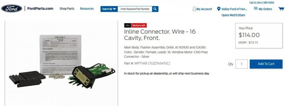
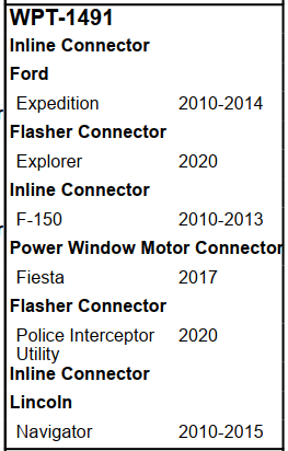
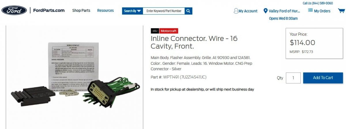
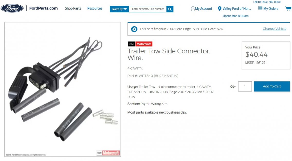
Pigtail repair kit pricing is absolutely nuts, perhaps due to supplying conductors for all 16 cavities because of the many applications of the connector across model lines...
Link to this FordParts webpage
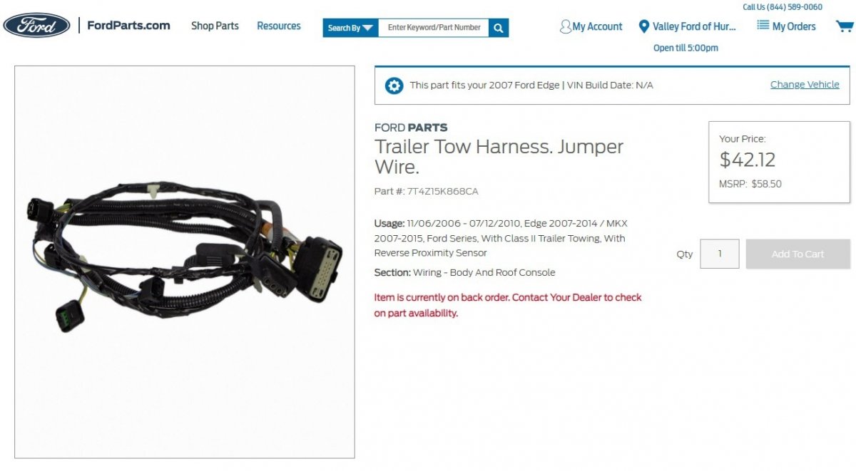
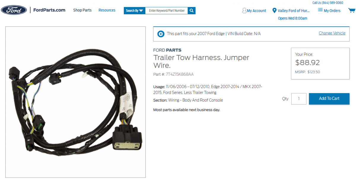
...when compared to the Service part equivalent to 2007 Edge Trailer Tow/Rear Parking Aid Sensors Harness 14N139...
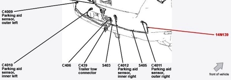
Link to this FordParts webpage
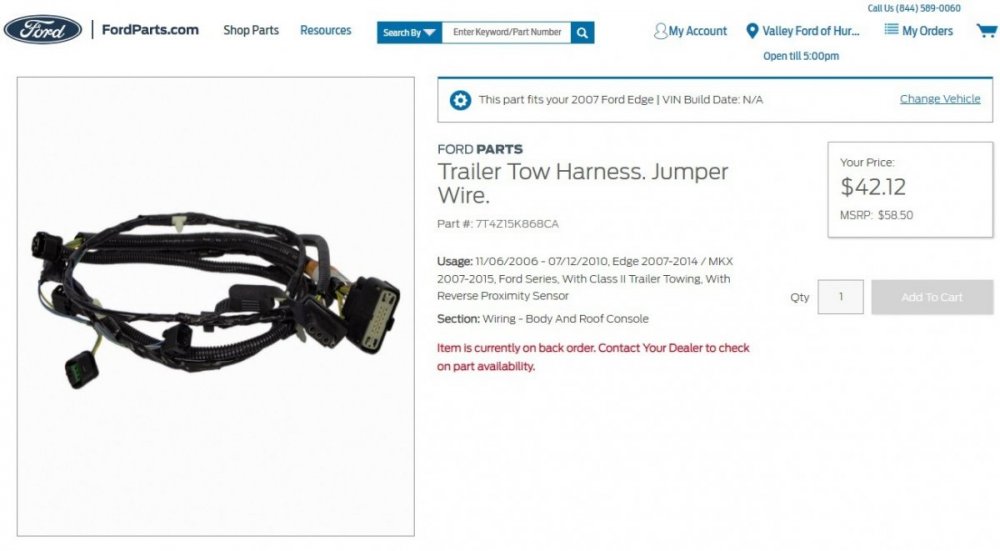
...which includes the 4-pole flat Trailer Lamps connector ...
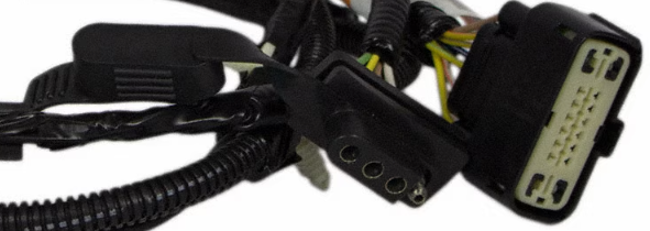
...compared to the Rear Parking Aid Sensors-Only Service Harness that costs more than twice the price of the above Trailer Tow Harness...

Doing web searches of these various part numbers may yield different pricing (and availability?) from other online sellers, compared to FordParts'.
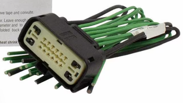
You may find Pigtail kits comparable to Motorcraft WPT-1491 on eBay by searching earlier connector designations of WPT-982 and WPT-1142, with pricing just under the Trailer Tow harness, with some connectors shipping from China sources.
I expect the connector-side conductors of the Trailer Tow harness for the Rear Parking Aid Sensors could be released and either zip-tied or fully removed from the Trailer Tow Harness' split-corrugated plastic sheathing, leaving only the Trailer Lamps conductors in the female-socketed Connector C406.
Additionally, you could be confident the conductor gauging is appropriately sized in the Trailer Tow harness, since conductor gauging in the Pigtail kits is not disclosed.
Good luck!
-
Welcome to the Forum, michaelwoosley !
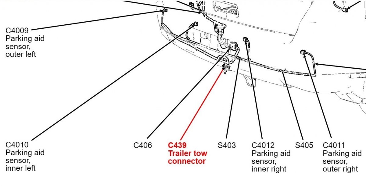
If you're seeing an unused factory connector dangling behind the center of the rear bumper cover, then your Edge is likely not equipped with Rear Parking Aid Sensors, and the connector is an Inline Connector C406, looking perhaps like a receptacle version of this...
Inline Connector C406
Inline Connector C406 conveys the Rear Parking Aid Sensor circuits and the Trailer Lamp circuits from Ford's grossly overpriced flat 4-pole Trailer Connector C439 (buy an aftermarket connector kit)...
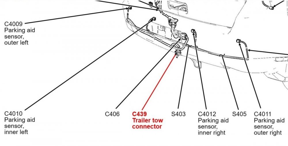
Link to Ford's online parts-selling site webpage

The more elaborate plug& play wiring harness kits you describe are for owners lacking a soldering iron and high-output hair dryer, but you strike me as being a 'cut & splice'-capable owner.
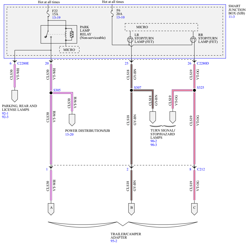
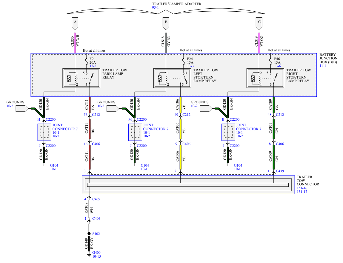
The 2007 Edge wiring diagrams have been updated to some extent, beyond what you show, and includes Smart Junction Box (SJB) involvement in addition to the Battery Junction Box (BJB)...
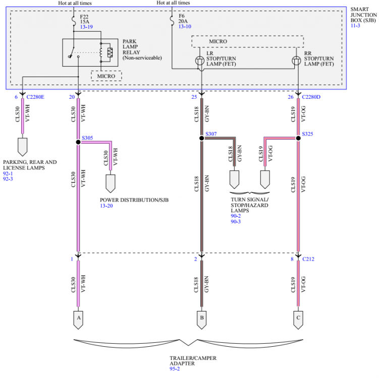
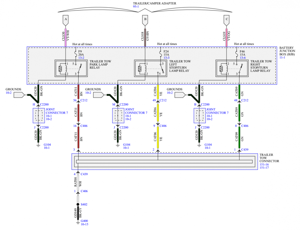
So, you'll be needing to likely verify the SJB fuse & relay and supply the three BJB relays for working Trailer Lamps operation -- in addition to installing a thriftier aftermarket 4-pole flat trailer-side connector.
Below are download links to resources I expect will get you across the Finish Line...
Document download links>
Trailer Tow - Smart Junction Box (SJB) Wiring Diagram - 2007 Edge.pdf
Smart Junction Box (SJB) Illustration - 2007 Edge.pdf
Smart Junction Box (SJB) Fuse & Relay Legend - 2007 Edge.pdf
Trailer Tow - Battery Junction Box (BJB) Wiring Diagram - 2007 Edge.pdf
Battery Junction Box (BJB) Illustration, Includes Trailer Tow Relay Locations - 2007 Edge.pdf
Battery Junction Box (BJB) Fuse & Relay Legend - 2007 Edge.pdf
Trailer Tow - Connector C439 & Connector C406 Locations - 2007 Edge.pdf
Inline Connector C406 Details - 2007 Edge.pdf
Trailer Tow - Connector C439 Details - 2007 Edge.pdf
Ford recommended splicing method.pdf
Trailer Lamps - Diagnosis and Testing - 2007 Edge Workshop Manual.pdf
If you require any additional information, just let me know -- and please let us all know once you've achieved Trailer Lamps success.
It's worth noting that the GEN 1 Edge Trailer Lamps set-up is simpler to add-in than adding Ford's Trailer Tow Module set-up to GEN 1+ & GEN 2 Edges/MKX/Nautilus.
Good luck!
-
1
-
-
Torus: Welcome to the Forum and congratulations on your diagnostic progress !
Because C211 is an inline connector, the connector details document only lists circuit identifiers in relation to the connector pins
To better equip you, I did some cutting & pasting and built a supplemental list that shows the involved components and electrical functions.
Document download links>
Inline Connector C211 – Pin-to-Circuit Identifier-to-Component Detail List – 2015 Edge.pdf
It's worth noting that your Edge may not be equipped with all the described circuits & components.
Good luck!
-
2
-
-
Yes, however, given the low voltage DTC -- and especially if all these DTCs popped up concurrently -- you may want to have the battery checked to ensure it's not failing or failed, since a bad battery can induce a multiplicity of DTCs and module misbehavior.
If the battery tests good, or you replace it, then clear all codes and see if any of the DTCs reoccur.
Good luck!
-
1
-


Special Service Message 52076 - 2019-2021 Edge/Nautilus - AWD - RDU Actuator Noise From The Rear Of The Vehicle When Approaching Vehicle Or Prior To Starting Engine
in Recalls, TSBs & Warranty
Posted · Edited by Haz
Supplemental information on Rear Drive Unit (RDU) operation and the RDU Actuator Motor's appearance and location...
Document download links>
Rear Drive Axle and Differential - System Operation and Component Description - 2019 Edge Workshop Manual.pdf
Rear Drive Unit (RDU) Actuator Motor - Removal and Installation - 2019 Edge Workshop Manual.pdf
Good luck!