


Haz
-
Posts
1,095 -
Joined
-
Last visited
-
Days Won
272
Content Type
Profiles
Forums
Gallery
Posts posted by Haz
-
-
Al: Have you scanned your Edge for Diagnostic Trouble Codes (DTCs) ?
From the System Operation and Component Description document...
Digital Signal Processor (DSP)
The audio system provides theater quality sound in the vehicle. Audio signals are sent from the ACM and APIM to the DSP module. The DSP module processes the audio signals and sends them to the speakers.
Additionally, from the 2018 Edge Workshop Manual, relating to: No Sound From All Speakers
Normal Operation and Fault Conditions
When the ignition status message from the BCM indicates that the engine is cranking, the ACM mutes the audio output.
If the audio DSP module detects an open, short to ground, or less than 3.5 volts on the enable circuit, the speaker output will be muted for all of the speakers.
A short to ground or short to voltage in the circuitry to one of the speakers may cause multiple speakers to lose sound due to the built-in overload protection feature of the audio DSP module. In this case, a speaker fault DTC sets.
DTC Fault Trigger Conditions
DTC Description Fault Trigger Conditions DTC Type B1142:27 Ignition Status 1: Signal Rate of Change Above Threshold Set by the ACM when an error is detected in the ignition status message from the BCM during engine start. Continuous B13FB:11 Audio Enable Line: Circuit Short To Ground Set by the audio DSP module when a short to ground is detected on the enable circuit Continuous Possible Sources
- Wiring, terminals, or connectors
- ACM
- Audio DSP module
I can provide diagnostic Pinpoint Test 'F' if either of the above DTCs are present in the ACM or DSP modules.
Good luck!
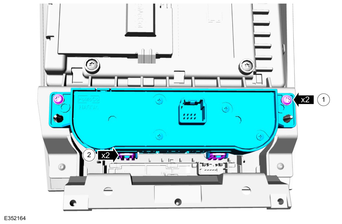
Document download link> Audio Digital Signal Processing (DSP) Module - Removal and Installation - 2018 Edge Workshop Manual.pdf
-
 1
1
-
Al: Have you tried using the Bezel Diagnostics procedure?
Your Edge's HVBoM shows originally fit unit as FT4T19C107HE.
As-Built data for your Edge's ACM shows as...
727-01-01 10A0 F000 00D0 727-01-02 0000 31 727-02-01 5B8C 727-03-01 3C6E 727-04-01 0001 0155 53DD Document download links>
Bezel Diagnostics - General Procedures - 2018 Edge Workshop Manual.pdf
Module Configuration - System Operation and Component Description - 2018 Edge Workshop Manual.pdf
Good luck!
-
2
-
-
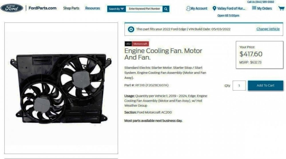
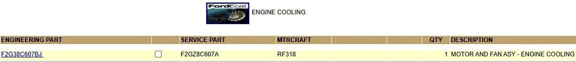
To supplement dabangsta's findings, I pulled Historical Vehicle Bill of Material (HVBoM) reports on 2022 & 2024 ST Performance Brake Package Edges and both confirm the Ford and Motorcraft part numbers...
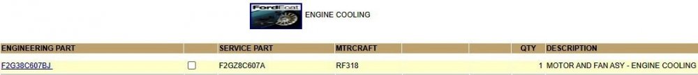
Similarly, those same part numbers are reflected on the FordParts website in reply to the same 2022 & 2024 ST Performance Brake Package Edge VINs...
Document download links>
Cooling Module - Removal and Installation - 2.7L EcoBoost - 2022-2024 Edge Workshop Manual.pdf
Good luck!
-
2
-
-
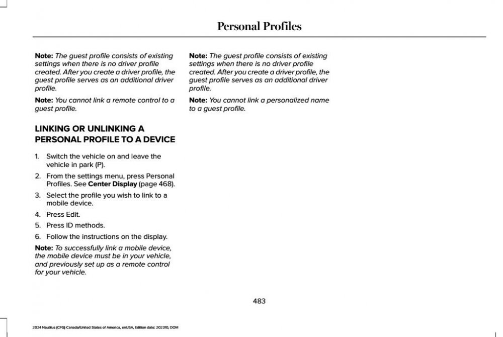
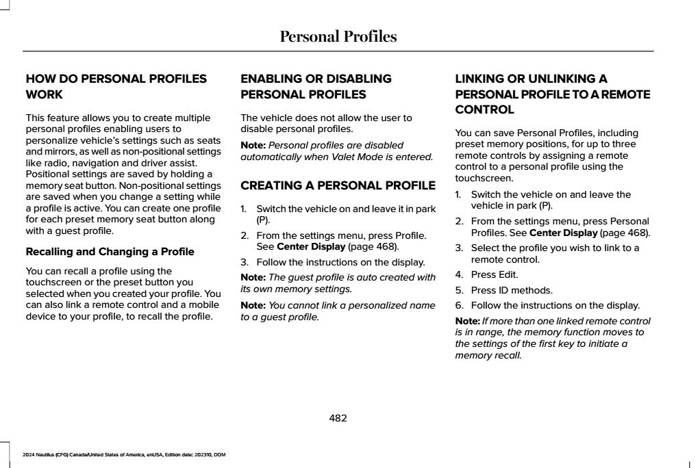
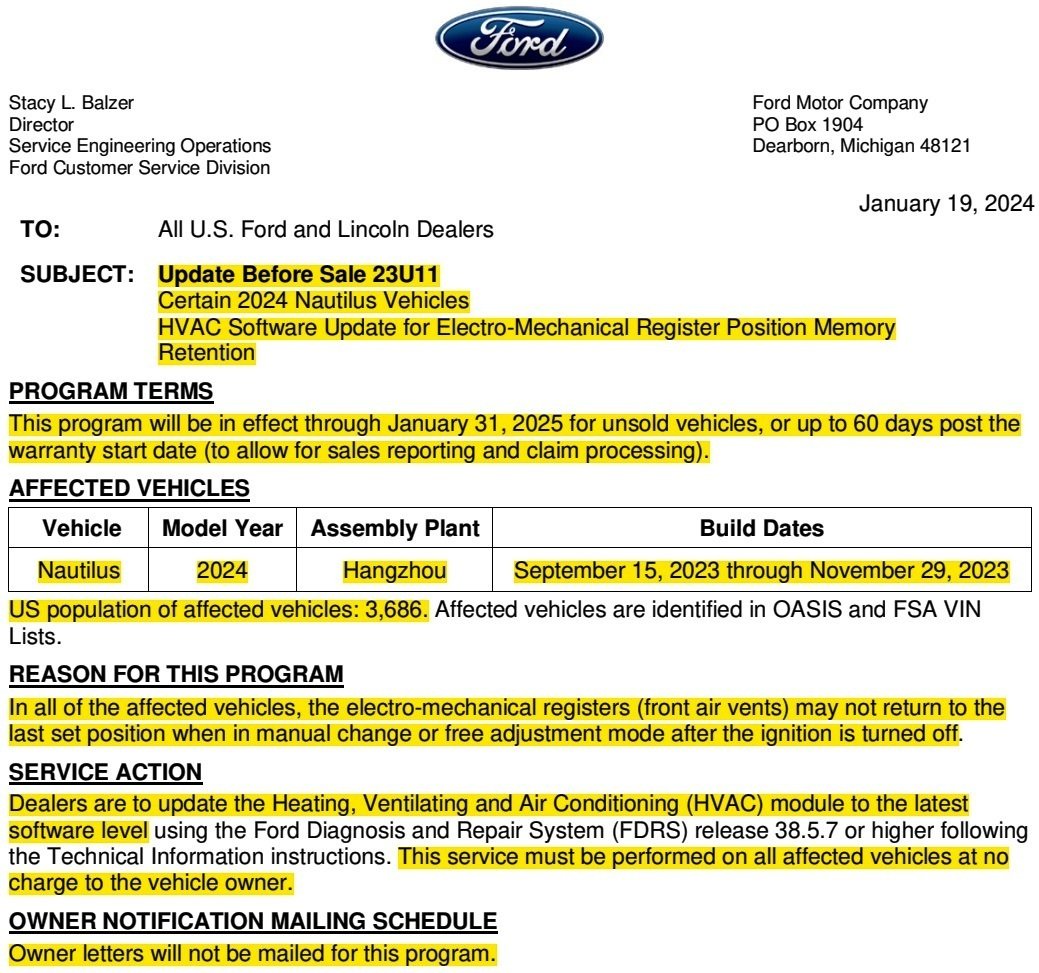
SSM 52231 - 2024 Nautilus - Audio Settings And Presets Will Not Save Some 2024 Nautilus vehicles may exhibit concerns with the last audio settings or audio presets not saving, audio system defaulting to AM radio, or memory seat settings not being retained. This may be due to the customer using a guest profile or inadvertently switching to a guest profile. Memory seat, audio presets, or last audio settings will not be retained when using a guest profile. Customers must set up a personnel profile and link the key fob and seat memory to a profile for these features/settings to remain in memory. Refer to the Personal Profiles section of the Owner Manual for further information. Customers may also be referred to the Lincoln YouTube Channel or Lincoln owners website for additional videos and information on how to use the features on their vehicle including how to set up a personal profile.
The referred-to Owner's Manual section...

-
1
-
-
14 hours ago, Termin8r said:
Haz; are you saying there should be a spoken command to turn of the audio via SYNC Voice Command?
Our 2015 MKX's comparatively Stone Age SYNC 2 system reacts to "Radio Off" and Radio On", though beginning the phrase with "Turn" confuses SYNC 2.
SYNC 4A is described as having Enhanced Voice Recognition, and being more capable with conversational expressions, so I expect that "Turn Radio Off" & "Turn Radio On" should be effective commands.
Good luck!
SYNC 4A with Enhanced Voice Recognition
2021 Edge Availability
SYNC 4A with Enhanced Voice Recognition is a one-stop shop for most of the vehicle controls, including applications, settings and climate controls. The SYNC 4A touchscreen offers a unique layout and larger font size for readability.
-
Status bar: Now supports up to six buttons and five icons
- Buttons include: Home, Settings, Camera, Android Auto™ or Apple CarPlay® (if activated), Alexa Built-in, Ford Power-Up software updates and Personal Profiles (if equipped). Certain buttons can be customized
- Icons include: Charging (if applicable), TA (traffic announcement), Wi-Fi, location sharing, phone signal strength, temperature and time
- Active screen: Displays the current feature in use, with Dash Cards below. A smaller version of Dash Cards now display up to six recently used apps that function as quick links. Swipe up or tap to launch a card into the active area and swipe down to close it
- Lower tray: Climate controls are always available here on-screen, along with audio volume/On/Off knob (if equipped). Pressing on temperature, fan or heated seat icons now enable the volume knob for quick level control, instead of sliders
-
Touchscreen features accessed on the Status Bar:
-
Applications drawer: Pressing the Home button brings up two tabs:
- Apps include both factory installed and third-party apps, as a phone is paired
- Entertainment includes games and music available for stationary times, like charging
- NOTE: Charging, Towing, Intelligent Backup Power, Zone Lighting and Pro Power Onboard are now native apps
-
Settings drawer: The Toggle button now brings up a consolidated view for quicker access:
- Controls, at the top of the menu, opens first by default when the drawer is open; Drive Modes, Camera and Seats are located here
- Settings, such as Sound, Phone List and Driver Assistance, can be accessed on the left menu
- Profiles drawer: Pressing the Personal Profiles button (if equipped) now brings up a dedicated drawer to see them and set up a new one
-
Applications drawer: Pressing the Home button brings up two tabs:
- Owners will appreciate cordless smartphone pairing, SiriusXM with 360L availability and Alexa Built-In compatibility. Up to 12 smartphones can be paired, but only two phones can be connected to Bluetooth® at the same time. Two phones cannot call or conference simultaneously
- The Ford Assistant allows owners to use conversational voice commands to talk to the vehicle and ask questions more like Siri or Alexa
-
Ford Sketch allows owners to draw, erase, clear, save and use different brush sizes directly on their SYNC 4A touchscreen
- They can also play tic-tac-toe and use a calculator with this feature (Mustang Mach-E only)
-
SYNC 4 Technology also carries over base embedded voice capability from SYNC 3, with the addition of a “wake word,” natural language understanding and one-shot Navigation search. The following embedded features are available regardless of whether a cloud connection is available in the vehicle:
- Phone controls, such as email message read and reply
- Navigation (with an active subscription) options, such as one-box search from main menu for addresses, Points of Interest (POI) and intersections
- Radio/media operation
- Climate features
- SYNC AppLink controls
-
The embedded voice allows the owner to use a “wake word” to talk to the vehicle. The wake word is turned Off by default but can be turned On in Settings. Go to Settings > Voice Control > Listen for Wake Word
- “OK, Ford” is the default wake word. Other options include “OK, FordPass,” “OK, Ford SYNC” or “Hello, Ford”
- A short press of the Push-to-Talk (PTT) button on the steering wheel can be used instead of the wake word. A long press of the PTT button will alert Android Auto or Apple CarPlay, if they are connected
- Penny Games: When the vehicle is stationary, owners will be able to entertain themselves with casual, quick to play games, including Sudoku, Doublesum, Jigsaw Puzzles, Lane Change and more
-
Using SYNC 4 Technology, owners can simultaneously connect two phones through Bluetooth. They can alternate between the two phones to call, answer, email and text. Either phone can be enabled to speak commands, stream media and use Android Auto/Apple CarPlay
NOTE: The Dual Phone feature does not allow the connection/conference of two calls from both phones.
-
1
-
Status bar: Now supports up to six buttons and five icons
-
From the 2012 Workshop Manual...
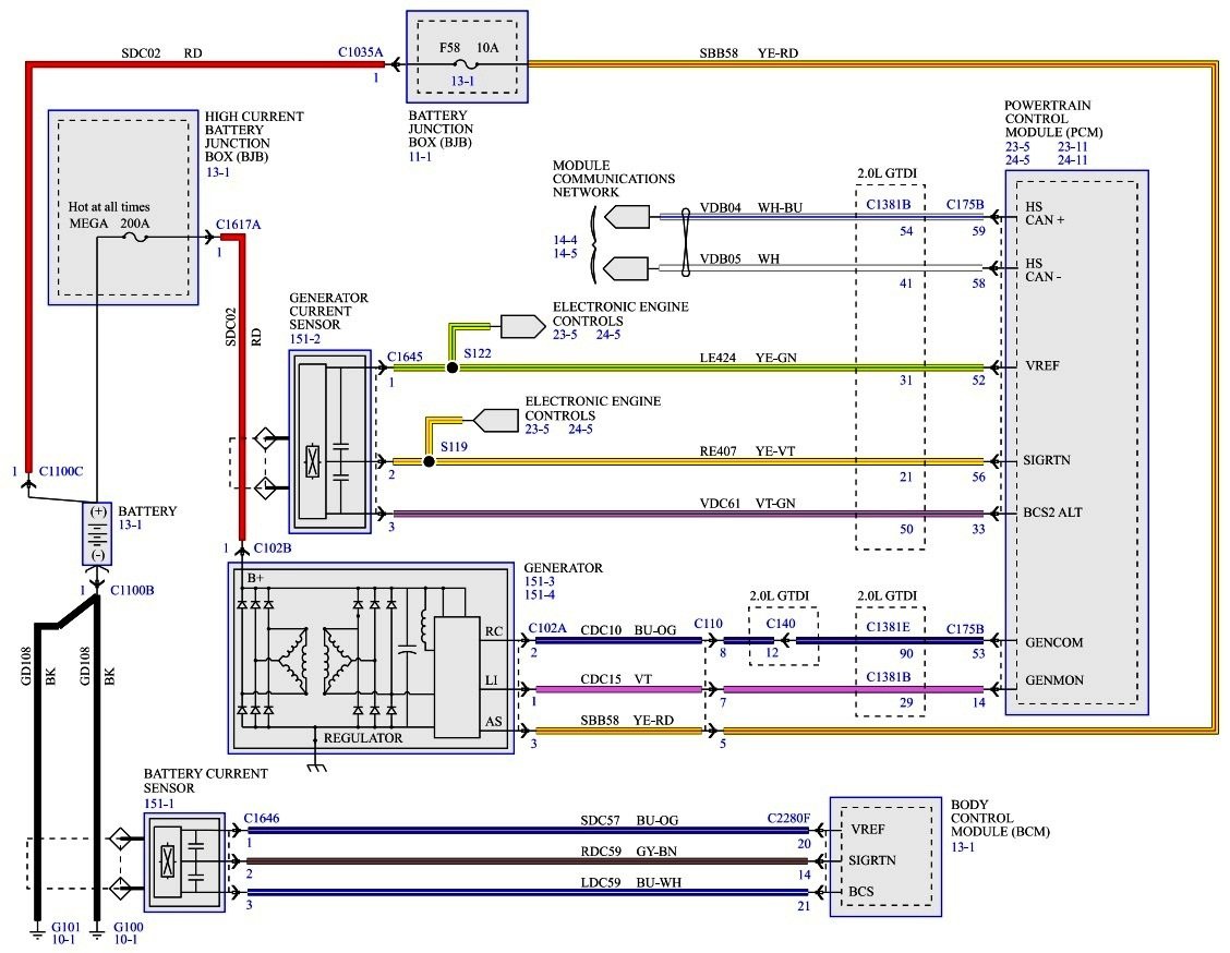
Pinpoint Test D - DTC P0625 or P0626 [Introduction - Full procedure is linked below]
Refer to Wiring Diagrams Cell 12 , Charging System for schematic and connector information [Pictured here and also linked below]...
Normal Operation [Emphasis added]
The PCM monitors the generator output via the generator monitor (GENMON) circuit. If the PCM cannot read the GENMON circuit due to an open or short to ground, when the engine rises above approximately 2,000 rpm, the generator defaults to a steady voltage of approximately 13.5 volts and the PCM sends a request to the Instrument Panel Cluster (IPC) to illuminate the charging system warning indicator. A GENMON duty cycle of 3% or less indicates a short to ground fault is present and results in DTC P0625 setting in the PCM. A GENMON duty cycle of 98% or more indicates an open or short to voltage fault is present and results in DTC P0626 setting in the PCM.
- DTC P0625 (Generator Field Terminal Circuit Low) — The PCM sets this DTC if the GENMON circuit is shorted to ground, the "A" sense circuit is open or the B+ circuit is open. This DTC also sets by a faulted PCM or generator.
- DTC P0626 (Generator Field Terminal Circuit High) — The PCM sets this DTC if the GENMON circuit is open or shorted to power. This DTC can also be set by a faulted PCM or generator.
This pinpoint test is intended to diagnose the following:
- Fuse
- Wiring, terminals or connectors
- Radial arm adapter
- Engine, generator and battery grounds
- Battery
- Generator
- PCM
Relevant wiring and connector information & Workshop Manual sections are linked immediately below.
Document download links>
Pinpoint Test D For DTC P0625 or P0626 - Diagnosis and Testing - 2012 Edge Workshop Manual.pdf
Charging System Wiring Diagram - 2012 Edge.pdf
Generator - Connector C102A Details - 2012 Edge.pdf
Generator - Connectors C102A & C102B Location - 2012 Edge.pdf
Powertrain Control Module (PCM) - Connector C175B Details - 2012 Edge.pdf
Powertrain Control Module (PCM) - Connector C175B Location - 2012 Edge.pdf
Charging System Principles of Operation - Diagnosis and Testing - 2012 Edge Workshop Manual.pdf
Good luck!
-
1
-
Welcome to the Forum, Anthony_a2 !
Diagnostic Trouble Codes (DTCs) may be present that can guide corrective efforts.
Try performing the Audio Control Module (ACM) Self-Diagnostic procedure, also known as Bezel Diagnostics.
From the 2010 Edge Workshop Manual...
Audio Systems With Navigation
- Turn the ACM on.
- Operate the audio system in radio tuner (AM/FM) mode.
-
Press and hold preset buttons 3 and 6 for 3 seconds until the speaker walk test begins.
- The display indicates each speaker as it is tested.
-
NOTE: If the speaker walk test is the only test required, this procedure can be stopped after this step, or by allowing the speaker walk test to complete on its own.
Before the speaker walk test is complete, press the "End Test" selection.
-
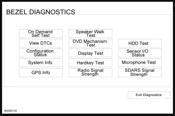
The following tests are available through the "BEZEL DIAGNOSTICS" menu:
Display Selection Diagnostic Function Description On Demand Self Test The ACM carries out a self-test. At the end of the self-test, the display either indicates "Test Passed" or lists any DTCs present. Note that the self-test may not indicate all DTCs that are present. If DTCs are suspected, retrieve continuous and on-demand DTCs using the scan tool. View DTCs The ACM displays any DTCs that are present. If there is more than a full screen of DTCs present, to scroll through the DTCs, press the down arrow on the display. If no DTCs are present, the display reads NO DTCS. Press the "Clear DTCs" selection to clear any DTCs present. Configuration Status The display shows the ACM configuration. A "0" indicates the item is configured off, while a "1" indicates the item is configured on. If the ACM appears to be misconfigured, refer to Section 418-01. System Info The ACM displays system information for various components of the audio system. The following items are most important for servicing the audio system: - Nav Radio Part Number — provides the ACM part number
- ESN1 — provides the satellite radio Electronic Serial Number (ESN)
GPS Info The current Global Positioning System (GPS) satellite information is shown, along with the current vehicle position. Pressing the "SV Status" selection provides additional information, if present. Speaker Walk Test The ACM carries out the speaker walk test. DVD Mechanism Test The ACM tests the internal CD/DVD drive mechanism. Display Test This test provides for testing of the touchscreen colors and the touchscreen sectors. Pressing any of the colors on the display causes the whole display to change to that color; pressing the display again returns to the Display Test menu. Pressing the "Touchscreen Activation Test" selection enters the touchscreen sector test. Press any area of the screen to test the touchscreen sector; press the "X" at the RH lower corner of the display to return to the Display Test menu. Hardkey Test This test provides for testing of the ACM buttons (not the touchscreen). When each button is pressed, the screen displays the button that is active. This test can also be used to isolate a stuck button. Radio Signal Strength The ACM displays the AM/FM antenna signal strength. To run this test, the audio system should be in AM radio tuner mode before entering the ACM self-diagnostic mode. HDD Test The ACM tests its internal hard drive. Sensor I/O Status The ACM displays inputs it is receiving from external sources. These inputs include: - Ignition — indicates ON (ignition in ACC or RUN) or OFF
- Brake — indicates ON (brake applied) or OFF (brake not applied)
- Illumination — indicates ON or OFF
- ReverseGear — indicates ON (vehicle in reverse) or OFF (vehicle not in reverse)
Microphone Test The ACM tests the microphone by supplying a test tone and monitoring the input from the microphone. As this vehicle is not equipped with a microphone, this test does not provide any diagnostic assistance. SDARS Signal Strength The ACM displays the satellite radio antenna signal strength.
- To exit the self-diagnostic mode, press the "Exit Diagnostics" selection from the "BEZEL DIAGNOSTICS" menu.
Please report back on the outcome, and then we'll determine if additional diagnostic procedures are necessary.
Good luck!
Illustration-2010EdgeWorkshopManual.jpg.287ef7920bebebbef435959e8828fd22.jpg)
-
2
-


Good luck!
-
2
-
 1
1
-
-
The audio system not powering-off via spoken SYNC command is an added symptom that dealership Service staff will explore, along with any related DTCs, if they exist.
The issue may involve corrupted software or a faulty module, apart from the audio control panel.
Online resources show your Edge's various SYNC & APIM software are up-to-date, but the dealership tech will connect your Edge to Ford's online Service systems to verify that, as well as to perform other diagnostic procedures comparable to Pinpoint Test J.
Establishing a relationship with a local dealer's Service department is a useful thing, especially if they participate in Ford's Pickup & Delivery Service.
As MLTEdge describes, absent overt physical damage, correcting this issue will very likely occur at no cost to you.
I can't speak to the Power pushbutton's depth of travel, if it is other-than a momentary contact control -- perhaps another GEN 2 Edge owner will clarify that.
Good luck!
-
1
-
-
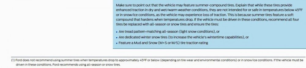
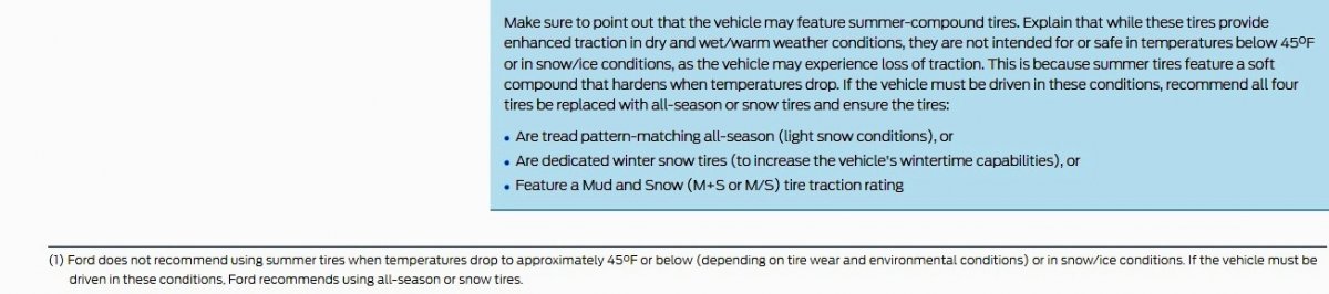
First released in December 2006, this instructive reference for Service Advisors and Technicians provides photos of tire conditions & guidance on whether they are warrantable or unwarrantable...

Document download link>
-
2
-
-
Based upon this description from the 2013 Edge Workshop Manual...
Steering Wheel Controls
The steering wheel controls are mounted directly to the steering wheel and wired to the Steering Column Control Module (SCCM) . Depending on what features the vehicle is equipped with, the SCCM sends messages via the High Speed Controller Area Network (HS-CAN) to the PCM (cruise control) and the Instrument Panel Cluster (IPC) (message center and entertainment system). The IPC receives the SCCM entertainment system messages via the HS-CAN and then sends them to the applicable entertainment system module(s) along the Infotainment Controller Area Network (I-CAN) .
...and this Front Control/Display Interface Module (FCDIM) - wiring diagram...
-WiringDiagram-2018Edge.thumb.jpg.81fd043048f7c968f955440b4251ffa7.jpg)
Your Edge's main plug may be the FCDIM Connector C2123...
-ConnectorC2123Image-2018Edge.thumb.jpg.421effdf298afa62d1aa22c59f8cc924.jpg)
If so, then your Aftermarket Head's two wires may find their rightful places on Pin 4 and Pin 5...
-ConnectorC2123Details-2018Edge.thumb.jpg.1c8e445b65bed3052f5a14ce6f94fa21.jpg)
Document download links>
FRONT CONTROL DISPLAY INTERFACE MODULE (FCDIM) - Wiring Diagram - 2018 Edge.pdf
FRONT CONTROL DISPLAY INTERFACE MODULE (FCDIM) - Connector C2123 Location - 2018 Edge.pdf
FRONT CONTROL DISPLAY INTERFACE MODULE (FCDIM) - Connector C2123 Details - 2018 Edge.pdf
Steering Wheel Switch, Right - Wiring Diagram without SYNC - 2013 Edge.pdf
Steering Wheel Switch, Right - Connector C2999 Location - 2013 Edge.pdf
Steering Wheel Switch, Right - Connector C2999 Details - 2013 Edge.pdf
Good luck!
-
1
-
-
-
Relating to the Battery Monitoring System (BMS) reset method and effects, this from the 2018 Edge Workshop Manual...
- If the vehicle battery is replaced, it is very important to perform the BMS Reset using a diagnostic scan tool.
- This reset is reserved for new battery installation. Resetting the battery monitoring system will clear the learned battery data, the battery time in service, and will affect the aging algorithm parameters, which have been learned since the installation of the battery.
- If the battery monitoring system reset is not carried out, it holds the old battery parameters and time in service counter in memory. Additionally it tells the system the battery is in an aged state and may limit the Electrical Energy Management system functions.
So, use of a diagnostic scan tool (including Forscan and other scanning apps) is the only way to perform a BMS reset.
The 8-hours is involved in the Body Control Module (BCM) validly tracking the battery's State of Charge, this from the 2018 Edge Workshop Manual...
- The BCM uses the battery current sensor (without auto-start-stop) or battery monitoring sensor (with auto-start-stop) to keep track of the battery state of charge. During a drive cycle the Electrical Energy Management software adjusts the battery state of charge up during charging, and down during discharge.
- During rest periods with the key off, and the vehicle enters sleep mode, the BCM automatically recalibrates the Battery State of Charge. It takes 8 hours in sleep mode, with the vehicle undisturbed, no doors opened or keyless entry buttons pressed, and the total vehicle current draw less than 300mA, to calibrate the battery state of charge to a high accuracy. If the system draw has not allowed the battery state of charge to calibrate over the previous 7 days, the state of charge quality factor changes to identify this and some Electrical Energy Management system functions may be temporarily turned off until a calibration takes place.
- This vehicle is equipped with an Electrical Energy Management system which manages battery charging and monitors the battery state of charge. The Electrical Energy Management system software is housed in the BCM . It has the algorithms and control structure for the Smart Regenerative Charging, and Load Shed Control Strategy. The Electrical Energy Management system is equipped with a battery current sensor (without auto-start-stop), or a battery monitoring sensor (with auto-start-stop) and generator current sensor to monitor the battery. These sensors serve as input to the Electrical Energy Management system software. If the sensors malfunction due to wiring issues or failure, a DTC will be set. In most cases the Electrical Energy Management system functions will be turned off until the sensor operation is restored.
So, while the 8-hours in sleep mode doesn't perform a BMS reset, it is comparably important.
Relating to the CHECK CHARGING SYSTEM message and/or the charging system warning indicator, this from the 2018 Edge Workshop Manual...
- The PCM reports any charging system faults and sends a message through the High Speed Controller Area Network (HS-CAN) to the BCM . The BCM controls the charging system warning indicator by sending a message over the Medium Speed Controller Area Network (MS-CAN) to the IPC . The IPC then controls charging system warning indication based on the message from the PCM through the BCM . The status of the PCM charging system warning indicator and/or message is confirmed by viewing PCM PID generator fault indicator lamp (GENFIL). Any charging system fault detected by the PCM results in 1 or more Diagnostic Trouble Codes (DTCs) being set and the PID GENFIL having a status of On. If equipped with a charging system warning indicator, the IPC turns the indicator on or off. If equipped with a message center, the IPC displays a CHECK CHARGING SYSTEM message. In some instances, the CHECK CHARGING SYSTEM message may not display if the ignition is on and the engine is off.
- Under certain circumstances, the charging system may have a concern but will still keep the battery charged and the vehicle running. GENCOM normally initiates charging but with a fault in this circuit, the generator can self-excite and start charging on its own. The charging system warning indicator is illuminated and/or the CHECK CHARGING SYSTEM message is displayed, and the generator operates in a default mode (approximately 13.5 volts).

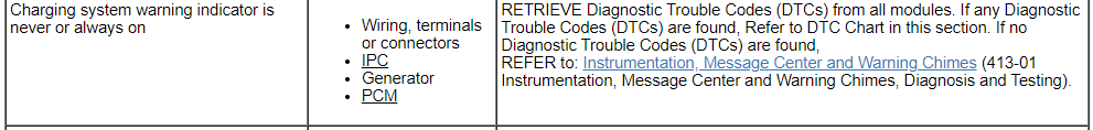


The Charging System RTT Warning Indicator Is Never Or Always On
Normal Operation and Fault Conditions
See Charging System RTT indicator.
REFER to: Message Center - System Operation and Component Description (413-01 Instrumentation, Message Center and Warning Chimes, Description and Operation).If the charging system indication request is missing for less than 5 seconds, the IPC defaults the charging system RTT indicator to the last indication state (on or off), based upon on the last message received.
If the charging system indication request is missing for 5 seconds or longer, the IPC defaults the charging system RTT indicator on.
Possible Sources
- Charging system concern
- Communication concern
- GWM concern
- IPC
PINPOINT TEST AJ: THE CHARGING SYSTEM RTT (RECONFIGURABLE TELLTALE) WARNING INDICATOR IS NEVER OR ALWAYS ON AJ1 CHECK THE MESSAGE CENTER OPERATION
- Ignition ON.
- Close all doors, the hood and the liftgate.
- Clear all message center warnings by pressing the OK button for each warning present.
- Monitor the door ajar RTT warning indicator.
- Open the driver door.
- Clear the message center popup warning.
- Monitor the door ajar RTT warning indicator.
Is the door ajar RTT warning indicator off with the door closed, and on with the door open?
Yes GO to AJ2 No

 VIN required to access Guided Routine (IPC)
AJ2 PERFORM THE IPC (INSTRUMENT PANEL CLUSTER) SELF-TEST- Using a diagnostic scan tool, perform the IPC self-test.
Are any Diagnostic Trouble Codes (DTCs) recorded?
Yes REFER to DTC Chart: IPC in this section. No GO to AJ3
AJ3 CHECK THE GWM (GATEWAY MODULE A) DIAGNOSTIC TROUBLE CODES (DTCS)- Using a diagnostic scan tool, check the GWM Continuous Memory Diagnostic Trouble Codes (DTCs).
Are any Diagnostic Trouble Codes (DTCs) recorded?
Yes
REFER to: Communications Network (418-00 Module Communications Network, Diagnosis and Testing).No GO to AJ4
AJ4 CHECK THE CHARGING SYSTEM OPERATION- Check the charging system operation.
Does the charging system operate correctly?
Yes If the charging system warning indicator is never on, the system is operating correctly at this time.
If the charging system warning indicator is always on, DIAGNOSE all BCM Diagnostic Trouble Codes (DTCs).
REFER to: Body Control Module (BCM) (419-10 Multifunction Electronic Modules, Diagnosis and Testing).No
REFER to: Charging System - 2.0L EcoBoost (184kW/250PS) – MI4 (414-00 Charging System - General Information, Diagnosis and Testing).
Relevant sections of the 2018 Edge Workshop Manual are linked for download below, and in an immediately following post, due to Forum file attachment limitations...
Document download links>
Charging System - 2.0L EcoBoost - Overview - 2018 Edge Workshop Manual.pdf
Message Center - System Operation and Component Description - 2018 Edge Workshop Manual.pdf
Battery Load Shed - Description and Operation - 2018 Edge Workshop Manual.pdf
-
1
-
SSM 52206 - 2024 Lincoln Nautilus - Reserve And Black Label - Knocking Type Noise From Rear Shock Absorber Area Some 2024 Lincoln Nautilus vehicles equipped with the Reserve and Black Label packages may exhibit a knocking noise from the rear shock absorber area of the vehicle while driving at speeds between 8 mph and 19 mph (13 km/h and 30 km/h) on rough road surfaces or when going over bumps. If the concern is isolated to the rear shock absorber assembly, replacing it at this time is unlikely to resolve the concern and is not recommended. This concern has no effect on vehicle operation or durability and is currently under investigation. Repair direction is expected late Q1 2024. Schedule a service appointment for this timeframe and monitor OASIS for additional information.
-
2
-
-
Document download link> Bezel Diagnostics - General Procedures - 2022-2024 Edge Workshop Manual.pdf
Good luck!
-
1
-
-
It is true that scanning your Edge's electronic modules will reveal any current and/or historical DTCs, including those associated with the Audio Control Panel.
Your good choice to invest in the longer-term Ford Protect CPO-Wraparound Premiumcare, to expand the covered items and extend the duration of the selling dealership's Blue Advantage Gold CPO, relieves you of any need to scan the Edge, unless you already have the device on hand.
The selling dealer's Service department will surely correct your Edge's radio power-off issue, and your being able to tell them whether or not the radio powers-off to your SYNC Voice Command may be useful to the Service Writer and Repair Tech as they seek the issue's root cause.
Your Edge's original factory Bumper-To-Bumper warranty coverage expires on August 13, 2024, so covered Warranty repairs to your vehicle should be performed at no cost to you through that date.
After that, the $100 deductible of your Ford Protect CPO-Wraparound contract will apply to covered repairs, except in the case of manufacturer Recall actions which are fulfilled at no cost to owners.
There are no unfulfilled Field Service Actions on your Edge, as a result of the selling dealer's completion of Recall 22S14 (link to details) in November 2023.
Once again, welcome to the Forum -- and congratulations on your 2021 Edge/CPO-wraparound purchase.
Good luck!
-
1
-
-
Document download link> Headlamp Assembly - Removal and Installation - 2022-24 Edge Workshop Manual.pdf
Good luck!
-
2
-
-
-
Providing full removal procedure with fastener locations for possible partial unfastening & repositioning to accomplish your task.
Document download link> Fender Splash Shield - Removal and Installation - 2022-2024 Edge Workshop Manual.pdf
Good luck!
-
1
-
-
I surveyed photos of 2021-2023 Edges offered for sale online and these images are representative of what I found...
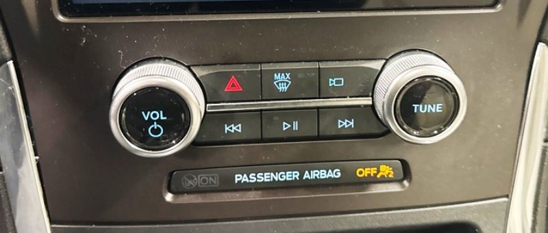
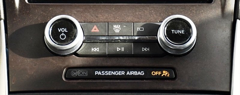
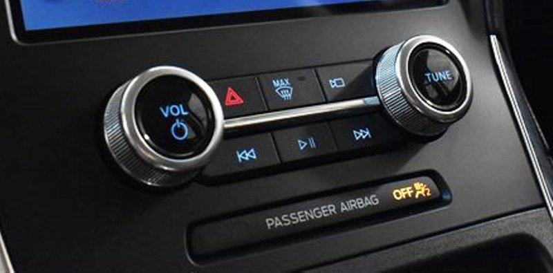
The Edge Workshop Manual offers 'Pinpoint Test J' as a diagnostic for the Audio Control Panel. Diagnostic Trouble Codes (DTCs) which are set for several faulty conditions...
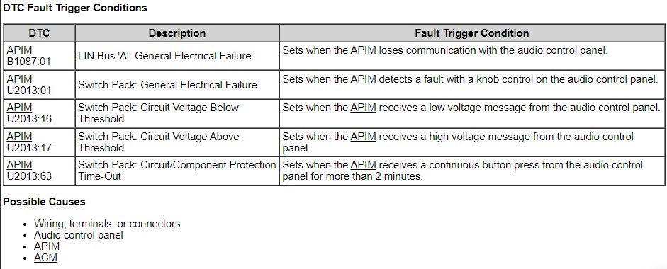
The DTCs for knob control fault and/or continuous button press may indicate an issue with the Power Button.
Given that the sales rep unsuccessfully addressed the radio power-off question with you, and, you've recognized the no-power-off issue after only two weeks, the selling dealer may consider covering the full repair cost or a shared-cost repair arrangement for your Edge.
- Have you tried using SYNC Voice Command to turn off the radio?
If the dealer refuses to cover any repair cost, and using SYNC Voice Command successfully turns radio power Off and On, then it's up to you to decide if the cost of a functioning Power button is worth it.
Additional Workshop Manual documents relating to the Audio Control Panel are attached for your awareness...
Document download links>
Audio Control Panel to SYNC Module Wiring Diagram - 2021 Edge.pdf
AUDIO CONTROL PANEL - Connector C2009 Details - 2021 Edge.pdf
AUDIO CONTROL PANEL - Connector C2009 Location - 2021 Edge.pdf
SYNC MODULE (APIM) - Connector C2383A Details - 2021 Edge.pdf
SYNC MODULE (APIM) - Connector C2383A Location - 2021 Edge.pdf
Audio Control Panel to Body Control Module (BCM) Wiring Diagram - 2021 Edge.pdf
Audio Control Panel to Ground Wiring Diagram - 2021 Edge.pdf
Audio Control Panel to HVAC Module Wiring Diagram - 2021 Edge.pdf
Audio Control Panel to Body Control Module (BCM) Hazard Lamps Wiring Diagram - 2021 Edge.pdf
Good luck!
-
3
-
Additional info...

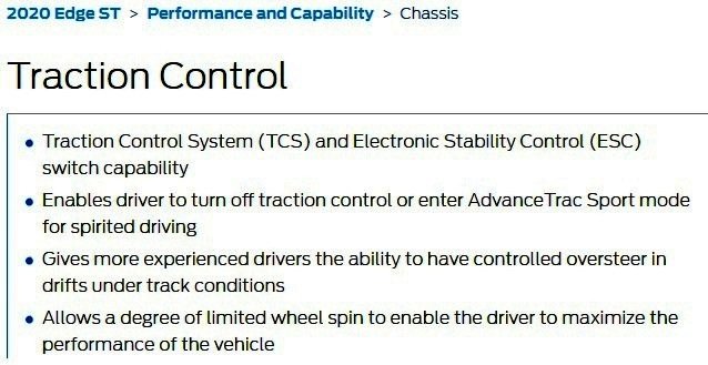
2019-2024 Edge Workshop Manuals all include the Sport Mode Traction Control engage/disengage instruction, along with a typo omitting the word spirited.
Placing your device cursor over underlined acronyms may yield full-word descriptions...
AdvanceTrac
The AdvanceTrac system is comprised of the traction control and ESC features.
Traction Control (TC)
The ABS module continuously monitors and compares the rotational speed of the drive wheels in relation to the non-driven wheels. When the drive wheels begin to spin faster than the non-driven wheels, the ABS module modulates brake pressure to the appropriate brake caliper(s) by opening and closing the appropriate solenoid valves inside the HCU while the hydraulic pump motor is activated. At the same time, the ABS module calculates how much engine torque reduction is required to eliminate the wheel slip and sends this torque reduction message along with a traction event message to the GWM over the HS-CAN2 . The GWM sends the engine torque reduction message to the PCM over the HS-CAN1 and the traction event message to the IPC over the HS-CAN3 . When the PCM receives the torque reduction message, it adjusts engine timing and decreases fuel injector pulses to reduce the engine torque to the requested level. When the IPC receives the traction event message it flashes the stability-traction control indicator (sliding car icon). Once the driven wheel speed returns to the desired speed, the ABS module returns the solenoid valves in the HCU to their normal position, deactivates the hydraulic pump motor and stops sending the traction event and torque reduction messages. The PCM returns engine timing and fuel injectors to normal operation and the IPC extinguishes the stability-traction control indicator (sliding car icon). After the vehicle speed exceeds 100 km/h (62 mph), traction control is accomplished only through the PCM torque control.
Traction control can be disabled using the traction control switch in the following manner:
- Momentarily pressing the switch disables only traction control, ABS , ESC and RSC remain enabled.
- Pressing the switch twice rapidly engages Sport Mode. Sport mode modifies the stability control intervention thresholds to allow for a more driving experience.
- Pressing the switch once after the system is deactivated fully enables the traction control system.
- Pressing the switch once after Sport mode is activated, deactivates Sport mode and fully enables the traction control system.
When the driver disables traction control, the IPC communicates traction control status to the GWM along the HS-CAN2 . The GWM sends the message to the ABS module along the HS-CAN2 . The ABS module takes no further action in regards to traction control until the driver activates the function or until the ignition is cycled from OFF to ON.
Traction control is disabled if there is a wheel speed sensor or solenoid valve DTC present in the ABS module. Traction control is also disabled if there is a communication error between the ABS module and the GWM . When traction control is disabled, the ABS module sends a message to the GWM along the HS-CAN2 which gateways the message to the IPC over the HS-CAN3 to illuminate the stability-traction control OFF indicator (sliding car OFF icon).
Electronic Stability Control (ESC)
The ABS module continuously monitors the vehicle motion relative to the intended course. This is done by using sensors to compare the steering wheel sensor messages, yaw rate sensor messages and longitudinal acceleration with the actual vehicle motion. On vehicles without active park assist, steering angle information is calculated by the PSCM and sent to the ABS module over the HS-CAN2 . On vehicles with active park assist, steering angle information is sent by the SCCM over the HS-CAN2 . Vehicle yaw rate and longitudinal acceleration information is sent to the ABS module from the RCM over the HS-CAN2 . If the ABS module determines from the inputs the vehicle is unable to travel in the intended direction, the brake pressure to the appropriate brake caliper(s) is modulated by opening and closing the appropriate solenoid valves inside the HCU while the hydraulic pump motor is activated. At the same time the ABS module calculates how much engine torque reduction is required to reduce vehicle speed to help stabilize the vehicle and sends this torque reduction message, along with an ESC event message, to the GWM over the HS-CAN2 . The GWM sends the torque reduction message to the PCM over the HS-CAN1 and the ESC event message to the IPC over the HS-CAN3 . When the PCM receives the torque reduction message, it adjusts engine timing and decreases fuel injector pulses to reduce the engine torque to the requested level. When the IPC receives this message, it flashes the stability-traction control indicator (sliding car icon).
Once the vehicle instability has been corrected, the ABS module returns the solenoid valves in the HCU to their normal position, deactivates the hydraulic pump motor and stops sending the ESC event and torque reduction messages. The PCM returns engine timing and fuel injectors to normal operation and the IPC extinguishes the stability-traction control indicator (sliding car icon).
ESC does not operate with the transmission in REVERSE. ESC is disabled if there is a wheel speed sensor, stability sensor or steering angle sensor DTC present in the ABS module. ESC is also disabled if there is a communication error between the ABS module and the PSCM , the ABS module and the RCM or the ABS module and the SCCM (if equipped). When ESC is disabled, the ABS module sends a message to the GWM along the HS-CAN2 which gateways the message to the IPC over the along the HS-CAN3 to illuminate the stability-traction control OFF indicator (sliding car OFF icon).
Roll Stability Control (RSC)
The ABS module continuously monitors the vehicle motion relative to the intended course. This is done by using sensors to compare the steering wheel sensor messages, yaw rate sensor messages, lateral acceleration sensor messages, longitudinal acceleration sensor messages and roll rate sensor messages with the actual vehicle motion. On vehicles without active park assist, steering angle information is calculated by the PSCM and sent to the ABS module over the HS-CAN2 . On vehicles with active park assist, steering angle information is sent by the SCCM over the HS-CAN2 . Vehicle yaw rate, lateral acceleration, longitudinal acceleration and roll rate information is sent to the ABS module from the RCM over the HS-CAN2 . If the ABS module determines from the inputs the vehicle is becoming unstable, the brake pressure to the appropriate brake caliper(s) is modulated by opening and closing the appropriate solenoid valves inside the HCU while the hydraulic pump motor is activated. At the same time the ABS module calculates how much engine torque reduction is required to help stabilize the vehicle and sends this torque reduction message, along with an RSC event message, to the GWM over the HS-CAN2 . The GWM sends the torque reduction message to the PCM over the HS-CAN1 and the RSC event message to the IPC over the HS-CAN3 . When the PCM receives the torque reduction message, it adjusts engine timing and decreases fuel injector pulses to reduce the engine torque to the requested level. When the IPC receives this message, it flashes the stability-traction control indicator (sliding car icon).
Once the vehicle instability has been corrected, the ABS module returns the solenoid valves in the HCU to their normal position, deactivates the hydraulic pump motor and stops sending the RSC event and torque reduction messages. The PCM returns engine timing and fuel injectors to normal operation and the IPC extinguishes the stability-traction control indicator (sliding car icon).
RSC does not operate with the transmission in REVERSE. RSC is disabled if there is a wheel speed sensor, stability sensor or steering angle sensor DTC present in the ABS module. RSC is also disabled if there is a communication error between the ABS module and the PSCM , the ABS module and the RCM or the ABS module and the SCCM (if equipped). When RSC is disabled, the ABS module sends a message to the GWM along the HS-CAN2 which gateways the message to the IPC over the along the HS-CAN3 to illuminate the stability-traction control OFF indicator (sliding car OFF icon).
Ford's advice to not use Sport Mode may be due to the outcome of a driver losing control of a vehicle having diminished TC/ESC reactive capability on public roads, compared to the same event occurring on a race track.
Good luck!
-
2
-
Document download links>
Generator - 2.7L EcoBoost - Removal and Installation - 2016 Edge Workshop Manual.pdf
Please note that several of the numbered action-step descriptions appear on the page prior to the illustration to which they apply, due to formatting for maximum illustration size.
Go Vols !
-
1
-
2
-
-
Welcome to the Forum, Termin8r !
As others have mentioned, from the 2021 Edge Owner's Manual...
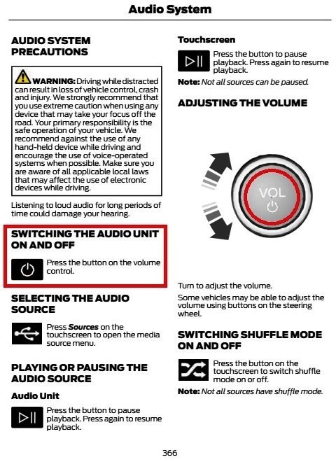
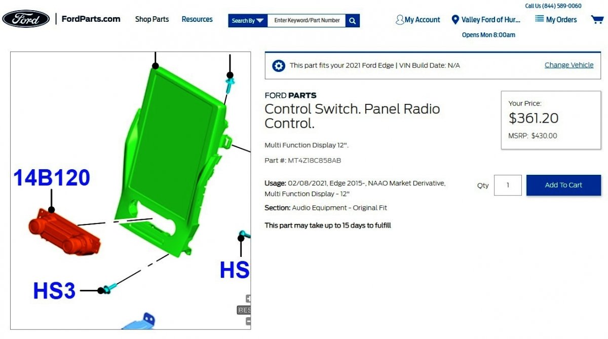
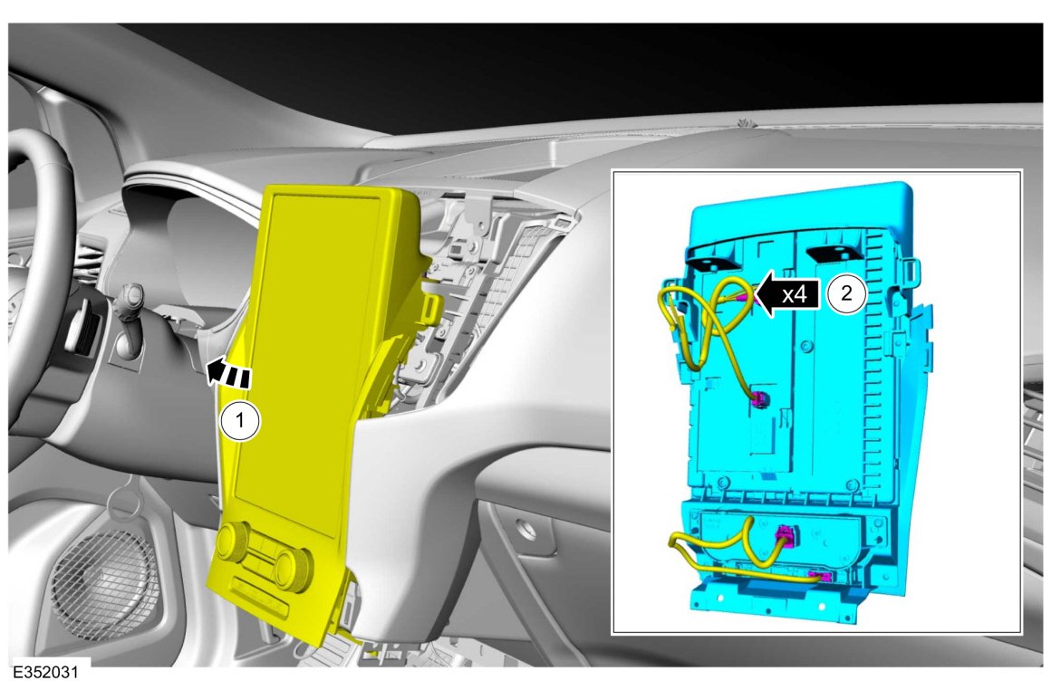
If the power switch function of the left control knob is faulty, the Radio Control Switch Panel is replaceable separate from the Display Screen...


Document download links>
Audio Controls - Removal and Installation - 2021 Edge Workshop Manual.pdf
Floor Console - Removal and Installation - 2021 Edge Workshop Manual.pdf
Good luck!
-
2
-
1
-
-
From the 2012 Edge Workshop Manual...
Battery Management System
Load Shed Strategy
NOTICE: When any vehicle module is being programmed, connect an external battery charger to make sure that the module programming is completed without the interruption due to the load shedding feature becoming active. The external battery charger must maintain a system voltage above 13 volts. This can require a charger setting higher than the lowest charge setting. The external battery charger negative connection must be made to an engine or vehicle chassis ground and not the negative battery terminal. If the connection is to the negative battery terminal, load shedding cannot be prevented from being invoked and module programming may be corrupted. After charging has begun, start the engine to clear any load shed states and then turn the engine off and proceed with programming.
NOTE: To maintain correct operation of the load shed, any electrical devices or equipment must be grounded to the chassis ground and not the negative battery terminal. A connection to the negative battery terminal can cause an inaccurate measurement of the battery state of charge and can cause incorrect load shed system operation.
This vehicle is equipped with a load shed strategy. The Body Control Module (BCM) uses the battery current sensor to keep track of the battery state of charge. The battery current sensor is a Hall-effect sensor attached to the battery ground cable. On vehicles equipped with Intelligent Access (IA) , the ignition state can also change.
Engine Off Load Shed
The BCM uses the battery current sensor to keep track of the battery state of charge. The battery current sensor is a Hall-effect sensor attached to the battery ground cable. When the engine is off, and the BCM determines the battery state of charge is below 40%, 10% of the charge has been drained or 45 minutes have elapsed, a load shed message is sent over the Controller Area Network (CAN) . This message turns off the audio system to save the remaining battery charge. Under this condition, a message may be displayed on the IPC or center stack display to alert the driver that battery protection actions are active.
When charging the vehicle battery by connecting the charger to the negative battery terminal is necessary, such as when using a combination battery charger and battery tester/analyzer, like the GR 1 190 V3.0 Intelligent Diagnostic Charger, the BCM will not immediately update the battery state of charge. In this instance, after charging, you must CARRY OUT the Battery Monitoring System (BMS) Reset using the scan tool. This reset is needed for proper engine off load shedding and to prevent invoking of engine off load shedding earlier than normal.
NOTE: If the reset is not carried out, when the battery is charged by connecting the charger to the negative battery terminal, it takes approximately 8 hours for the BCM to learn the new battery state of charge. During this 8 hour period, the vehicle must be undisturbed, with no doors opened or keyless entry button presses. If the vehicle is used before the BCM is allowed to learn the new battery state of charge, engine off load shedding can still occur and a message may be displayed.
When charging the vehicle battery by connecting the charger to engine or chassis ground, the negative charger clamp must be connected to an unpainted chassis surface or a solid engine component such as a generator mount or engine lifting eye. In this instance, after charging, the BMS reset is not required if the ignition was ON during charging by above method. Through this method of charging, the BCM updates the battery state of charge during the charging process. If the ignition was OFF during charging by above method, a BMS reset may be required since the BCM does not update battery state of charge with ignition key OFF unless the vehicle is parked undisturbed for 8 hours.
Document download link> Charging System - Diagnosis and Testing - 2012 Edge-MKX Workshop Manual.pdf
Good luck!
-
3
-


-WiringDiagram-2018Edge.jpg.3a04b89d1900886b74f9b7222552b4ce.jpg)
-ConnectorC2123Image-2018Edge.jpg.114b650098cf9cba1c12f340cc431e74.jpg)
-ConnectorC2123Details-2018Edge.jpg.baed6356b65717f36d04e6f4773ce4ea.jpg)

2018 Edge Audio Control Module - No sound
in Audio, Backup, Navigation & SYNC
Posted
Because you have a record of the modules exhibiting DTCs in your Forscan screen capture(s), I would try performing a Clear All Codes, followed by performing Self Test routines on all modules for which Forscan previously indicated DTCs.
From my perspective, the outcome of the Self Tests will indicate fault states currently existing, versus those previously shown which were historical, but are not currently faulted -- if that makes any sense.
My hope would be that the DSP's DTC-indicated fault that is capable of blocking speaker audio may be historical, and clearing the DTC may restore the speaker audio -- but I may be wrong.
Initially clearing all DTCs and performing the Self Tests is easier/quicker than the disassembly needed to access & perform Pinpoint Test F's circuits/connectors volt/ohm evaluations.
If this B13FB:11 DTC reoccurs, there is Pinpoint Test F for you -- or a dealership technician -- to perform...
Did the ACM and audio DSP module pass the network test?
REFER to: Communications Network (418-00 Module Communications Network, Diagnosis and Testing).
F2 CHECK FOR SPEAKER DIAGNOSTIC TROUBLE CODES (DTCS)
Are any speaker fault Diagnostic Trouble Codes (DTCs) present?
F3 CHECK THE ENABLE CIRCUIT FUNCTIONALITY BY CHECKING THE AUDIBLE PROMPT FUNCTIONALITY
Does the SYNC® system produce an audible prompt correctly; indicating voice recognition mode has been entered?
F4 CHECK FOR AN AUDIO SIGNAL TO THE AUDIO DSP (AUDIO DIGITAL SIGNAL PROCESSING MODULE) MODULE
NOTICE: This pinpoint test step directs testing circuits using a back-probe method. Use the special back-probe tool POM6411. Do not force test leads or other probes into connectors. Adequate care must be exercised to avoid connector terminal damage, while ensuring that good electrical contact is made with the circuit or terminal. Failure to follow these instructions may cause damage to wiring, terminals, or connectors, and may cause subsequent electrical faults.
Is a fluctuating AC voltage present?
F5 CHECK THE AUDIO DSP (AUDIO DIGITAL SIGNAL PROCESSING MODULE) MODULE ENABLE CIRCUIT FOR CORRECT VOLTAGE
NOTICE: This pinpoint test step directs testing circuits using a back-probe method. Use the special back-probe tool POM6411. Do not force test leads or other probes into connectors. Adequate care must be exercised to avoid connector terminal damage, while ensuring that good electrical contact is made with the circuit or terminal. Failure to follow these instructions may cause damage to wiring, terminals, or connectors, and may cause subsequent electrical faults.
Is the voltage between 3.5 and 8.5 volts?
F6 CHECK THE AUDIO DSP (AUDIO DIGITAL SIGNAL PROCESSING MODULE) MODULE ENABLE CIRCUIT FOR A SHORT TO VOLTAGE
Is any voltage present?
F7 CHECK THE AUDIO DSP (AUDIO DIGITAL SIGNAL PROCESSING MODULE) MODULE ENABLE CIRCUIT FOR A SHORT TO GROUND
Is the resistance greater than 10,000 ohms?
F8 CHECK THE AUDIO DSP (AUDIO DIGITAL SIGNAL PROCESSING MODULE) MODULE ENABLE CIRCUIT FOR AN OPEN
Is the resistance less than 3 ohms?
F9 CHECK FOR CORRECT ACM (AUDIO FRONT CONTROL MODULE) OPERATION
Is the concern still present?
REFER to: Audio Front Control Module (ACM) (415-00C Information and Entertainment System - General Information - Vehicles With: Sony Audio System, Removal and Installation).
F10 CHECK FOR CORRECT AUDIO DSP (AUDIO DIGITAL SIGNAL PROCESSING MODULE) MODULE OPERATION
Is the concern still present?
REFER to: Audio Digital Signal Processing (DSP) Module (415-00C Information and Entertainment System - General Information - Vehicles With: Sony Audio System, Removal and Installation).
Below, and in an immediately following post due to Forum attachment limitations, are download links to wiring diagrams, connector information, and module access procedures in support of Pinpoint Test F efforts...
Document download links>
Front Controls Interface Module (FCIM) - Removal and Installation - 2018 Edge Workshop Manual.pdf
Front Display Interface Module (FDIM) - Removal and Installation - 2018 Edge Workshop Manual.pdf
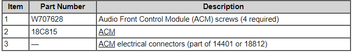
Audio Front Control Module (ACM) - Removal and Installation - 2018 Edge Workshop Manual.pdf
Loadspace Trim Panel - Removal and Installation - 2018 Edge Workshop Manual.pdf
Audio Front Control Module (ACM) to Audio Digital Signal Processing (DSP) Module Wiring Diagram - 2018 Edge w Sony.pdf
AUDIO DIGITAL SIGNAL PROCESSING (DSP) MODULE - Power Distribution Wiring Diagram - 2018 Edge w Sony.pdf
AUDIO DIGITAL SIGNAL PROCESSING (DSP) MODULE to Speakers - Wiring Diagram 1 - 2018 Edge w Sony.pdf
AUDIO DIGITAL SIGNAL PROCESSING (DSP) MODULE to Speakers - Wiring Diagram 2 - 2018 Edge w Sony.pdf
AUDIO DIGITAL SIGNAL PROCESSING (DSP) MODULE to Speakers - Wiring Diagram 3 - 2018 Edge w Sony.pdf
DSP-ACM-APIM - Wiring Diagram - 2018 Edge w Sony.pdf
Audio Front Control Module (ACM) to Audio Digital Signal Processing (DSP) Module - Inline Connector C210 Details - 2018 Edge w Sony.pdf
Audio Front Control Module (ACM) to Audio Digital Signal Processing (DSP) Module - Inline Connector C210 Location - 2018 Edge w Sony.pdf
AUDIO DIGITAL SIGNAL PROCESSING (DSP) MODULE - Connector C4362A Details - 2018 Edge w Sony.pdf
AUDIO DIGITAL SIGNAL PROCESSING (DSP) MODULE - Connector C4362B Details - 2018 Edge w Sony.pdf
AUDIO DIGITAL SIGNAL PROCESSING (DSP) MODULE - Connector C4362C Details - 2018 Edge w Sony.pdf
AUDIO FRONT CONTROL MODULE (ACM) - Connector C240B Details - 2018 Edge w Sony.pdf