


Haz
-
Posts
1,568 -
Joined
-
Last visited
-
Days Won
437
Content Type
Profiles
Forums
Gallery
Posts posted by Haz
-
-
Dealer Software Support Hotline (DSSH) authorization requirements are being expanded to the ordering of Powertrain Control Modules (PCM) replacements for 2023+ Model Year vehicles...
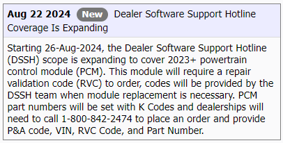

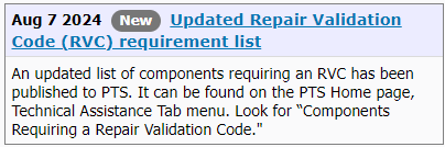
Announcing the Dealer Software Support Hotline (DSSH) Update
Always use the PTS Diagnostics Tab and Workshop Manual to determine the correct diagnostic for your vehicle concern.
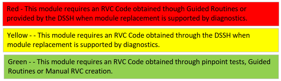
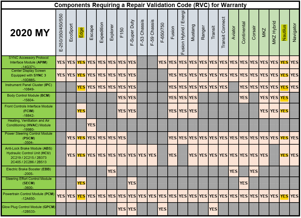
Modules in this chart require a Repair Validation Code (RVC) using the following process:
Red – This module requires an RVC obtained through Pinpoint Tests, Guided Routines or provided by the DSSH when module replacement is supported by diagnostics. Yellow - This module requires an RVC obtained through the DSSH when module replacement is supported by diagnostics. Green - This module requires an RVC obtained through Pinpoint Tests, Guided Routines or Manual RVC creation.
IMPORTANT: If you are required to submit a Technical Support Request (TSR) to the DSSH you must do this prior to module removal.
NOTE: This Chart will be updated frequently to keep you informed of policy changes regarding module replacements. Be sure to check here often; a PTS What's New will be released with each updated chart.
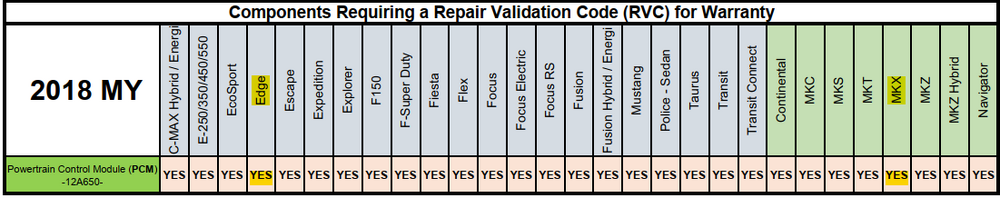
Components Requiring a Repair Validation Code (RVC) for Warranty* (updated 09/2024)
*Always check the warranty start date to confirm warranty coverage.2018 Model Year Vehicle Powertrain Control Module
(PCM)
-12A650-2018 - All Vehicles under 8,500 GVW YES
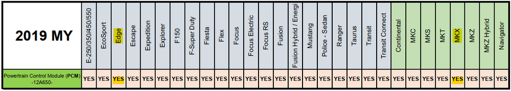
2019 Model Year Vehicle Powertrain Control Module
(PCM)
-12A650-2019 - All Vehicles under 8,500 GVW YES
2020 Model Year Vehicle SYNC Accessory Protocol Interface Module
(APIM)
-14G371- / -14G670-Display Screen Equipped with
SYNC
-10D885-Image Processing Module A
(IPMA)
-14G647- / -19H406-Image Processing Module B
(IPMB)
-19H405-Powertrain Control Module
(PCM)
-12A650-Power Steering Control Module
(PSCM)
-3504-Body Control Module
(BCM)
-15604-Electric Brake Booster
(EBB)
-2005-Steering Effort Control Module
(SECM)
-3600-Anti-Lock Brake Module (ABS)
Hydraulic Control Unit (HCU)
2C219 / 2C215 / 2B373
2C405 / 2C286 / 2B513Heating, Ventilation and Air Conditioning Module
(HVAC)
-19980-Front Controls Interface Module
(FCIM)
-18842-Instrument Panel Cluster
(IPC)
-10849-Glow Plug Control Module
(GPCM)
-12B533-2020 Aviator YES YES YES YES YES YES 2020 Continental YES YES YES YES YES YES YES YES 2020 Corsair YES YES YES YES YES YES YES 2020 EcoSport YES YES YES YES YES 2020 Edge YES YES YES YES YES YES YES YES 2020 Escape YES YES YES YES YES YES YES 2020 Expedition YES YES YES YES YES YES 2020 Explorer YES YES YES YES YES YES YES 2020 F-150 YES YES YES YES YES YES YES YES YES 2020 F-250-600 Super Duty YES YES YES YES YES YES YES YES YES 2020 F-53 Motorhome/F-59 Strip Chassis YES YES 2020 Fusion YES YES YES YES YES YES YES YES 2020 Fusion Hybrid/PHEV YES YES YES YES YES YES YES 2020 MKZ YES YES YES YES YES YES YES YES 2020 MKZ Hybrid YES YES YES YES YES YES YES 2020 Mustang YES YES YES YES YES YES YES YES 2020 Nautilus YES YES YES YES YES YES YES YES 2020 Navigator YES YES YES YES YES YES 2020 Ranger YES YES YES YES YES YES 2020 Transit YES YES YES YES YES YES YES 2020 Transit Connect YES YES YES YES YES YES
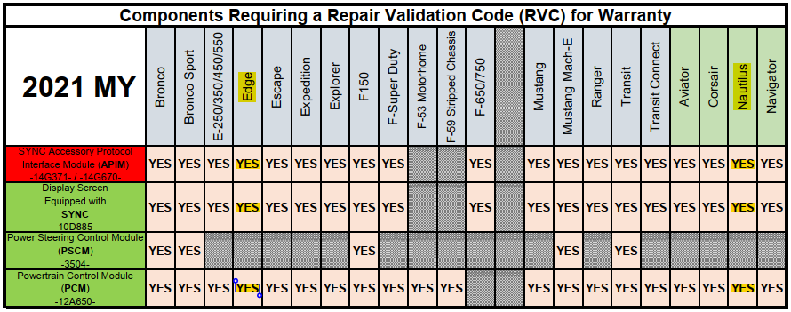
2021 Model Year Vehicle SYNC Accessory Protocol Interface Module
(APIM)
-14G371- / -14G670-Display Screen Equipped with
SYNC
-10D885-Image Processing Module A
(IPMA)
-14G647- / -19H406-Image Processing Module B
(IPMB)
-19H405-Powertrain Control Module
(PCM)
-12A650-Power Steering Control Module
(PSCM)
-3504-2021 Aviator YES YES YES 2021 Bronco YES YES YES YES 2021 Bronco Sport YES YES YES YES 2021 Corsair YES YES YES 2021 E-350/450 YES YES YES 2021 EcoSport YES YES YES 2021 Edge YES YES YES 2021 Escape YES YES YES 2021 Expedition YES YES YES 2021 Explorer YES YES YES 2021 F-150 YES YES YES YES 2021 F-250-600 Super Duty YES YES YES 2021 F-53 Motorhome/F-59 Strip Chassis YES 2021 F-650/750 YES YES YES 2021 Mustang YES YES YES 2021 Mustang Mach-E YES YES YES YES 2021 Nautilus YES YES YES 2021 Navigator YES YES YES 2021 Ranger YES YES YES 2021 Transit YES YES YES YES 2021 Transit Connect YES YES YES
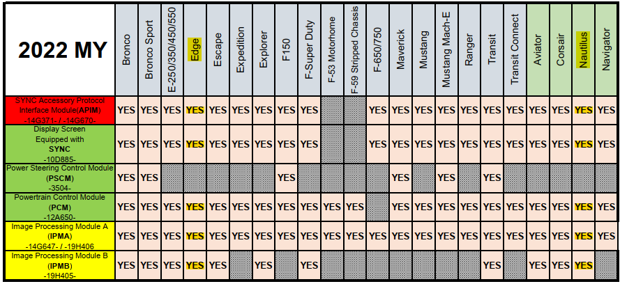
2022 Model Year Vehicle SYNC Accessory Protocol Interface Module
(APIM)
-14G371- / -14G670-Display Screen Equipped with
SYNC
-10D885-Image Processing Module A
(IPMA)
-14G647- / -19H406-Image Processing Module B
(IPMB)
-19H405-Powertrain Control Module
(PCM)
-12A650-Power Steering Control Module
(PSCM)
-3504-2022 Aviator YES YES YES YES YES 2022 Bronco YES YES YES YES YES YES 2022 Bronco Sport YES YES YES YES YES YES 2022 Corsair YES YES YES YES YES 2022 E-350/450 YES YES YES YES 2022 EcoSport YES YES YES 2022 Edge YES YES YES YES YES 2022 Escape YES YES YES YES YES 2022 Expedition YES YES YES YES 2022 Explorer YES YES YES YES YES 2022 F-150 YES YES YES YES YES 2022 F-250-600 Super Duty YES YES YES YES YES 2022 F-53 Motorhome/F-59 Strip Chassis YES YES 2022 F-650/750 YES YES YES YES 2022 Maverick YES YES YES YES YES 2022 Mustang YES YES YES YES 2022 Mustang Mach-E YES YES YES YES YES 2022 Nautilus YES YES YES YES YES 2022 Navigator YES YES YES YES 2022 Ranger YES YES YES YES 2022 Transit YES YES YES YES YES YES 2022 Transit Connect YES YES YES YES
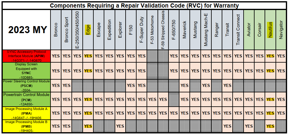
2023 Model Year Vehicle SYNC Accessory Protocol Interface Module
(APIM)
-14G371- / -14G670-Display Screen Equipped with
SYNC
-10D885-Image Processing Module A
(IPMA)
-14G647- / -19H406-Image Processing Module B
(IPMB)
-19H405-Powertrain Control Module
(PCM)
-12A650-Power Steering Control Module
(PSCM)
-3504-2023 Aviator YES YES YES YES YES 2023 Bronco YES YES YES YES YES YES 2023 Bronco Sport YES YES YES YES YES YES 2023 Corsair YES YES YES YES 2023 E-350/450 YES YES YES YES 2023 Edge YES YES YES YES YES 2023 Escape YES YES YES YES 2023 Expedition YES YES YES YES 2023 Explorer YES YES YES YES YES 2023 F-150 YES YES YES YES YES 2023 F-250-600 Super Duty YES YES YES YES YES 2023 F-53 Motorhome/F-59 Strip Chassis YES YES 2023 F-650/750 YES YES YES YES 2023 Maverick YES YES YES YES YES 2023 Mustang YES YES YES YES 2023 Mustang Mach-E YES YES YES YES YES 2023 Nautilus YES YES YES YES YES 2023 Navigator YES YES YES YES 2023 Ranger YES YES YES YES 2023 Transit YES YES YES YES YES YES 2023 Transit Connect YES YES YES YES
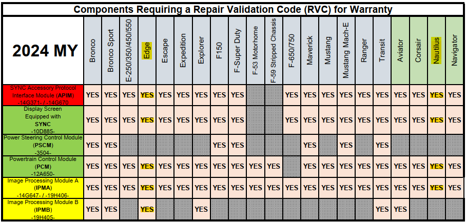
2024 Model Year Vehicle SYNC Accessory Protocol Interface Module
(APIM)
-14G371- / -14G670-Display Screen Equipped with
SYNC
-10D885-Image Processing Module A
(IPMA)
-14G647- / -19H406-Image Processing Module B
(IPMB)
-19H405-Powertrain Control Module
(PCM)
-12A650-Power Steering Control Module
(PSCM)
-3504-2024 Aviator YES YES YES YES YES 2024 Bronco YES YES YES YES YES YES 2024 Bronco Sport YES YES YES YES YES YES 2024 Corsair YES YES YES YES 2024 E-350/450 YES YES YES YES 2024 Edge YES YES YES YES YES 2024 Escape YES YES YES YES 2024 Expedition YES YES YES YES 2024 Explorer YES YES YES YES YES 2024 F-150 YES YES YES YES YES 2024 F-250-600 Super Duty YES YES YES YES YES 2024 F-53 Motorhome/F-59 Strip Chassis YES YES 2024 F-650/750 YES YES YES YES 2024 Maverick YES YES YES YES YES 2024 Mustang YES YES YES YES 2024 Mustang Mach-E YES YES YES YES YES 2024 Nautilus YES YES YES YES 2024 Navigator YES YES YES YES 2024 Ranger YES YES YES YES 2024 Transit YES YES YES YES YES YES
2025 Model Year Vehicle SYNC Accessory Protocol Interface Module
(APIM)
-14G371- / -14G670-Display Screen Equipped with
SYNC
-10D885-Image Processing Module A
(IPMA)
-14G647- / -19H406-Image Processing Module B
(IPMB)
-19H405-Powertrain Control Module
(PCM)
-12A650-Power Steering Control Module
(PSCM)
-3504-2025 Aviator YES YES YES YES 2025 Bronco YES YES YES YES YES YES 2025 Bronco Sport YES YES YES YES YES 2025 Corsair YES YES YES YES 2025 E-350/450 YES YES YES 2025 Escape YES YES YES YES 2025 Expedition YES YES YES YES 2025 Explorer YES YES YES YES 2025 F-150 YES YES YES YES YES 2025 F-250-600 Super Duty YES YES YES YES YES 2025 F-53 Motorhome/F-59 Strip Chassis YES 2025 F-650/750 YES YES YES 2025 Maverick YES YES YES YES YES 2025 Mustang YES YES YES YES 2025 Mustang Mach-E YES YES YES YES YES 2025 Navigator YES YES YES YES 2025 Ranger YES YES YES YES 2025 Transit YES YES YES YES YES -
 3
3
-
-
-
Special Service Message 52820 - 2019-2024 Various Vehicles – “Location” Toggle Button Grayed Out - Location Sharing Cannot Be Disabled
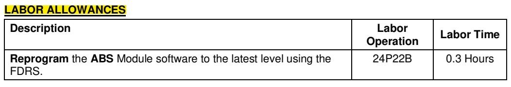
Some 2019-2024 Ford and Lincoln vehicles equipped with a telematics control unit module (TCU) may exhibit the “Location” toggle button in the Connectivity setting menu grayed out with an inability to switch it off. This may be due to the TCU software. To correct the condition and allow the customer to switch off the vehicle location setting, using Ford Diagnostic and Repair System (FDRS) select "BCM - Transport and Factory Mode Deactivation”, and select "unlock vehicle connectivity settings" and then press "Continue" to unlock the "Location" button. For claiming, use causal part 14G087 and applicable labor operations in Section 10 of the Service Labor Time Standards (SLTS) Manual.
-
1
-
-
Edge / MKX / Nautilus models ARE NOT INVOLVED in this Advance Notice Safety Recall...
@enigma-2: The answer to your question...
-
@omar302: Here's the 2016 version...
Center Registers - Removal and Installation - Climate Control System - 2016 Edge Workshop Manual.pdf
And, the above-attached 2017 document has been re-uploaded.
Good luck!
-
2
-
-
Gratitude to @enigma-2 for resurrecting @Holmy's wintertime question.
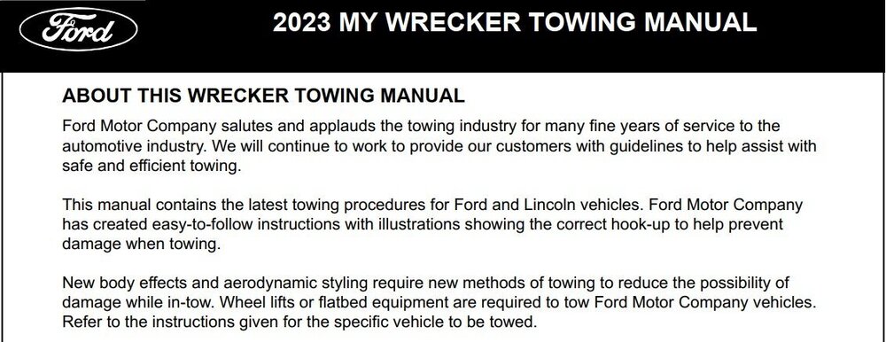
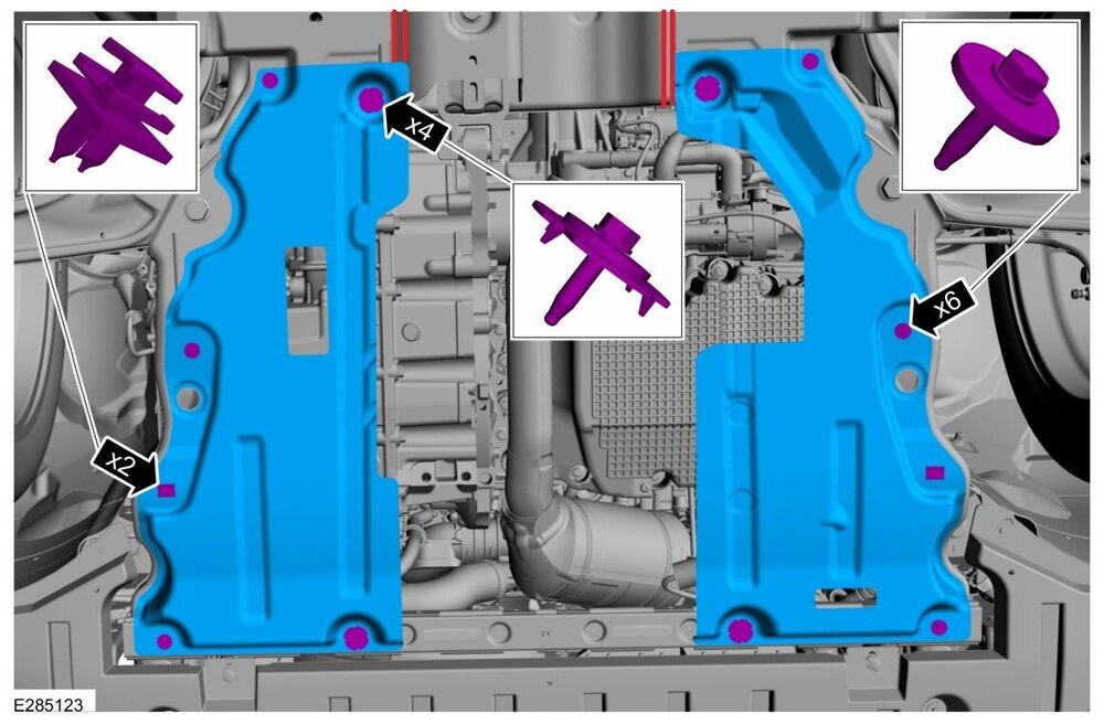
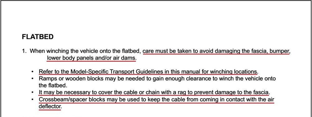
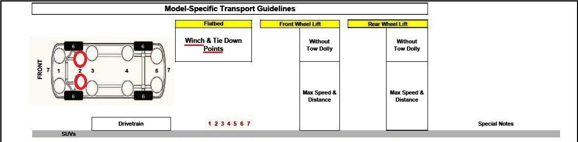
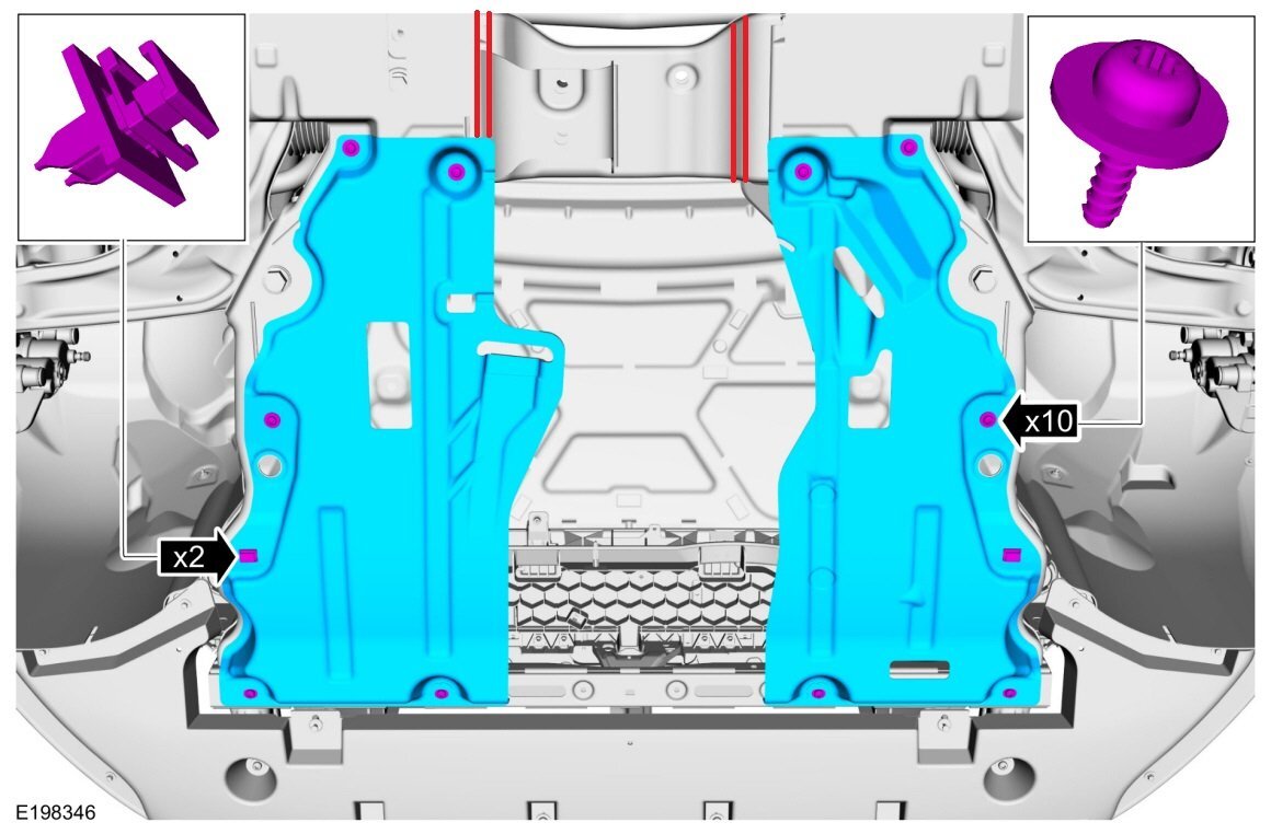
Ford produces manuals by Model Year to guide vehicle recovery efforts by professional Wrecker drivers...
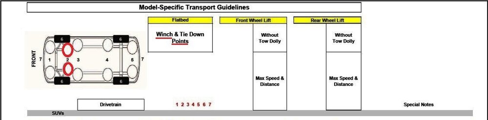


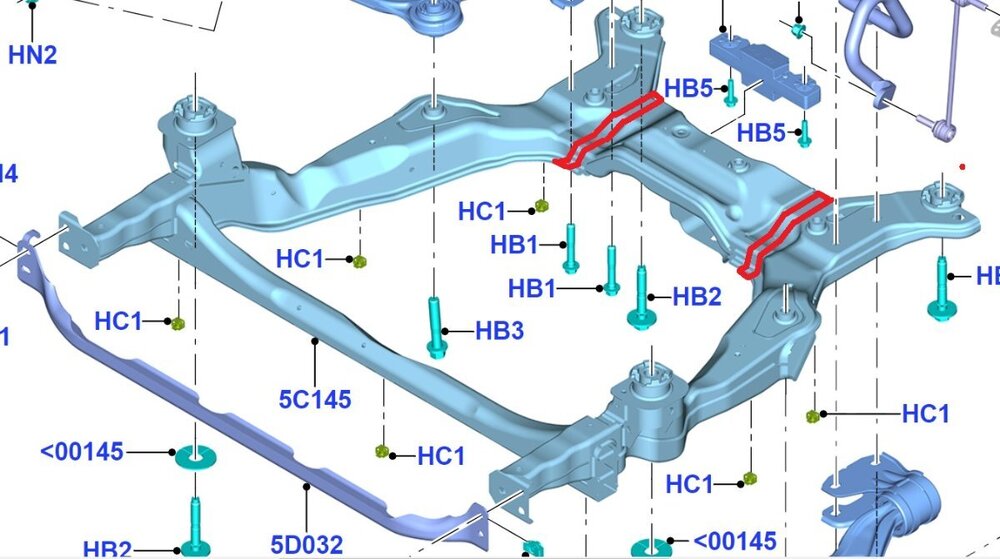
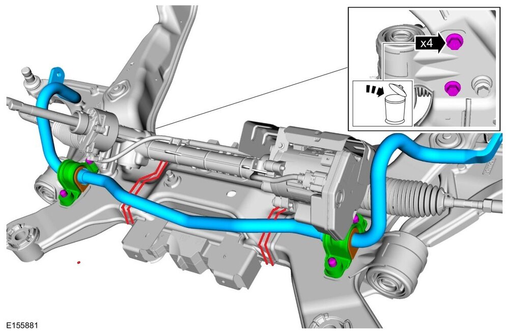
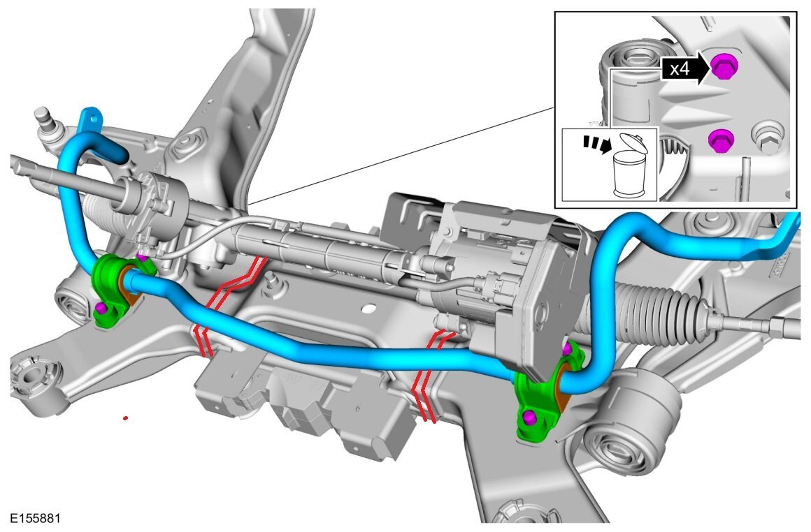
The following Workshop Manual images have been red-lined in areas expected to correspond to the #2 designation...
Front Subframe, rear crossmember
Front Subframe, Rear Crossmember, with Steering Gear and Anti-Roll Bar Installed
One-Piece Front Underbody Shield In Place, blocks access to Front Subframe
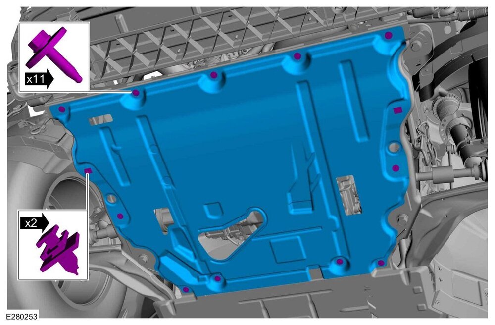
Two-Piece Front Underbody Shield In Place
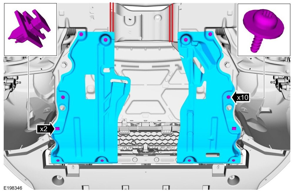
Two-Piece Front Underbody Shield In Place, Alternate View
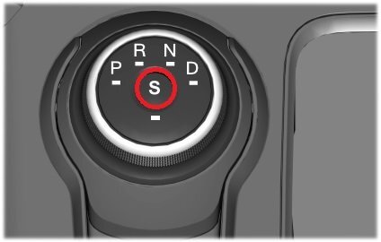
Transmission shift-by-wire technology in some Edge/Nautilus model years requires awareness of Automatic Return to Park and Stay in Neutral Mode.
From the Workshop Manual...
Rotary Dial Shift Modes
Automatic Return to Park
NOTE: This feature does not operate when your vehicle is in Stay In Neutral Mode or neutral tow.
The vehicle has a safety feature that will automatically shift the transmission into P when one of the following conditions are met at low speed:
- The ignition is turned off and vehicle falls below low speed threshold
- The driver door is opened with the seat belt unlatched
- Unlatching the safety belt while the driver door is open
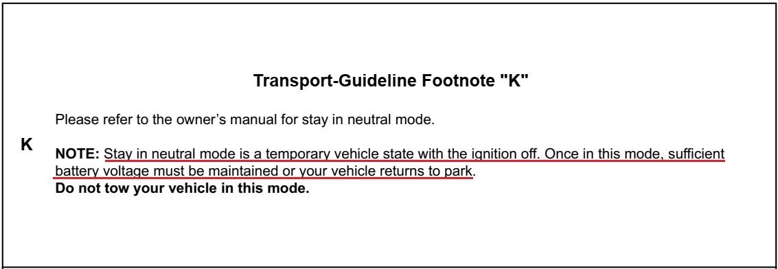
Stay in Neutral Mode
If necessary for the vehicle to stay in N without the driver present, such as being pulled through a car wash, this mode disables Return to Park. In Stay in Neutral the system will remain awake draining the battery if the engine is off. When you enter neutral at low speed a message will be displayed stating press the S button to stay in neutral mode. Then, if the driver presses the S button within the time limit, the message Stay in Neutral Mode appears on the multifunction display. During this mode the N position on the GSM flashes continuously and the instrument cluster will display N as the selected gear. To exit the Stay in Neutral Mode, shift out of neutral.
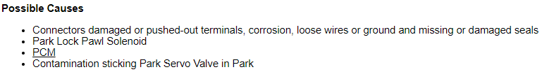
If the battery discharges while in Stay in Neutral Mode, the Park Lock Pawl Solenoid will release and transmission will return to Park. Do not tow the vehicle in this mode.
Gear Shift Module (GSM) Image with 'S' button red-circled
This awareness requirement is reinforced by Ford's Manual for Wrecker drivers as Footnote 'K'...

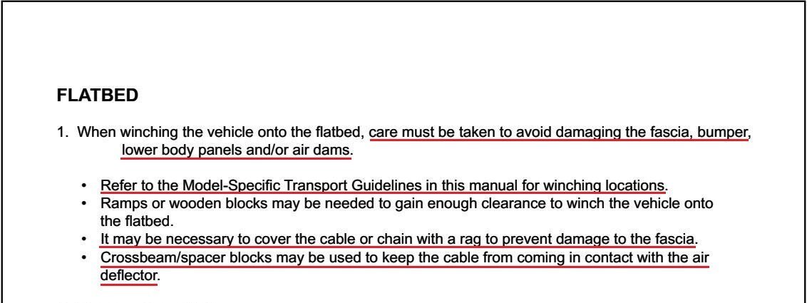
Using a J-Hook bridle around the outside of the Front Sub-Frame's Rear Crossmember is easier than wrapping a strap around the crossmember -- and preferred to attaching to suspension A-arms, which Ford does not recommend...
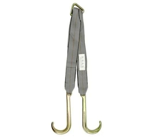

Mindfulness toward not damaging a vehicle's facia/bumper cover is also advised...
With all of that said, an installed trailer hitch and one of these makes things a lot easier...

And, if hazards require the vehicle to be unoccupied during recovery, use Stay In Neutral Mode on shift-by-wire vehicles.
Good luck!
-
2
-
Welcome to the Forum @schareco5!
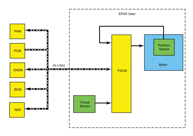
Because you describe your Edge's steering wheel as not controlling your vehicle, the following is a description of the Electronic Power Assist Steering (EPAS) system from the 2022-2024 Edge Workshop Manual...
Placing your device cursor over the underlined acronyms may yield full-words descriptions of the acronyms.
Power Steering - System Operation and Component Description
System Operation
System Diagram
Network Message Chart
Module Network Input Messages: Power Steering Control Module (PSCM)
Broadcast Message Originating Module Message Purpose ABS active ABS Used to confirm that the ABS is operational. Power mode BCM Used to confirm the ignition status of the vehicle. Stability control brake active ABS Used to confirm the operational state of the stability control system. Steering angle counter SASM Used to verify the validity of the steering angle message. Steering angle status SASM Used to confirm the steering angle sensor is initialized and operating correctly. Steering wheel direction of rotation SASM Used to confirm the direction in which the EPAS motor is driven. Traction control brake active ABS Used to confirm the operational state of the traction control system. Transport mode BCM Used to confirm the vehicle is in normal operation mode, factory mode, transport mode or a crash event has been identified and the vehicle has been set to a post crash configuration. Vehicle configuration/information ABS Used to compare the PSCM configuration against the vehicles specific configuration (central car configuration). Vehicle speed ABS Used to determine the level of assist supplied. Wheel speed data ABS Used to validate the steering wheel component angle by comparing the rotational speeds of each wheel. The difference in the speed of each wheel is used to derive a steering angle for comparison against the absolute steering angle message from the SASM .
EPAS System
The PSCM controls the functions of the EPAS system and communicates with other modules over the HS-CAN2 .
To activate, the EPAS system needs to be connected to battery voltage at the hot at all times input and at the ignition-run input to the PSCM . In addition, the system must communicate with other modules over the HS-CAN2 . The PSCM must receive the power mode signal from the BCM in order to be set into operation mode.
The main input for calculating the level of EPAS assist is the steering torque sensor signal. Vehicle speed is also taken into consideration in order to achieve the vehicle speed dependent steering assist characteristic.
The EPAS gear uses a reversible motor to apply the steering assist. The motor is connected to the rack of the steering gear by a toothed belt and pulley-bearing assembly.
The motor is used by the PSCM to move the rack inside the steering gear housing.
The PSCM continually monitors and adjusts steering efforts based on the steering torque sensor signal, motor position and HS-CAN2 inputs to enhance the feel of the steering system. As vehicle speed increases, the amount of assist decreases to improve and enhance road feel at the steering wheel. As vehicle speed decreases, the amount of assist increases to ease vehicle maneuvering. Compensation is made to reduce the effect of pull or drift that can be experienced when driving on roads with a high degree of camber. Also compensation for the impact of wheel imbalance on steering feel is made up to a predetermined threshold.
The steering torque sensor senses the torque at the steering wheel. It is integrated into the PSCM and works by measuring the relative rotation between an input and output shaft which are connected by a torsion bar. The steering torque sensor sends out 2 PWM signals which allows a channel to channel cross-check and an accurate correction of the neutral point.
The PSCM is self-monitoring and is capable of setting and storing Diagnostic Trouble Codes (DTCs). Depending on the DTC set, the PSCM may enter a failure mode. In addition, the PSCM may send a request to the IPC to display a message in the message center, alerting the driver of a potential EPAS concern. The warning message is sent over the HS-CAN2 to the GWM where it is converted to a HS-CAN3 message and forwarded on to the IPC over the HS-CAN3 .
Failure Modes
When a DTC is present in the PSCM , the EPAS enters 1 of 2 modes of operation.
The EPAS system enters a reduced steering assist mode to protect the internal components of the EPAS system when a concern is detected by the PSCM such as low or high battery voltage or over-temperature concerns not considered to be a critical safety concern. This reduced steering assist mode gives the steering a heavier than normal feel.
The EPAS system enters a manual steering mode (no electrical steering assistance is provided) when a concern considered to be a critical safety concern is detected. In manual steering mode, the vehicle has mechanical steering operation only, which gives steering operation a heavy feel.
There are 3 failure strategies used by the PSCM for determining failure modes. The first strategy is limp home; when the PSCM detects a fault requiring the EPAS to switch to a failure mode, the PSCM calculates a "safe" level of torque assist and provides this assist until the ignition is cycled. If the fault remains during the next ignition cycle, the PSCM switches to manual steering mode until the fault is repaired. If the fault is not present during the next ignition cycle, the PSCM resumes normal operation and steering assist.
The next strategy is limp aside; similar to the limp home strategy except the limp aside strategy can recover normal steering assist during the same ignition cycle if the fault is no longer present or the ignition is cycled. If the fault is still present, the PSCM switches to manual steering mode until the fault is repaired.
The last strategy is ramp down; the PSCM uses all the various inputs to calculate a torque output command to provide steering assist, if the module cannot calculate this output, it uses the last known good torque command to provide steering assist until the PSCM completely removes assist and switches to manual steering mode until the fault is repaired.
Component Description
EPAS Steering Gear
The EPAS gear is an assembly that consists of a PSCM , a motor, and a steering torque sensor, all of which are serviced as an assembly. The inner and outer tie rods and the gear bellows boots are available for service.
- The steering torque sensor is mounted near the input shaft of the EPAS gear and is used by the PSCM to determine how much force is being used to turn the steering wheel.
- The EPAS gear has one inner tie rod located at each end of the gear assembly and is available separately for service.
- The EPAS gear has one outer tie rod located at each end of the gear assembly and is available separately for service.
- The EPAS gear has one bellows boot located at each side of the EPAS gear assembly. Each boot is held in place with 2 boot clamps. The boots and clamps are available for service.
PSCM
The PSCM is the ECU for the EPAS system. The module monitors all sensor inputs and HS-CAN2 messages that relate to the EPAS system and directly controls the output of the EPAS motor.
Attached below as PDF documents are three Diagnostic Pinpoint Tests used by dealership Service Technicians. Each provides step-by-step guidance toward analyzing the kinds of symptoms you describe. You may be able to address some portion of the evaluation yourself.
If you have not already, it may be useful to have your Edge scanned for Diagnostic Trouble Codes (DTCs), which can provide fuller guidance toward resolving any contributing issues. Typically, nationwide-brand auto parts stores will perform electronic module scans. If you choose to do this, document the scanner results by taking smartphone photos of the found DTC descriptions displayed on the scanner and feel free to report them out here.
Good luck!
Power Steering - System Operation and Component Description - 2022-2024 Edge Workshop Manual.pdf Diagnostic Pinpoint Test ''B'' - Unable To Replicate Customer's Intermittent Assist Concern During A Test Drive - 2022-2024 Edge Workshop Manual.pdf Diagnostic Pinpoint Test ''G'' - Steering Sytem Pull, Drift Or Wander - 2022-2024 Edge Workshop Manual.pdf Diagnostic Pinpoint Test ''F'' - Excessive Wheel Play - 2022-2024 Edge Workshop Manual.pdf
-
1
-
-
Welcome to the Forum @EdgeGT350!
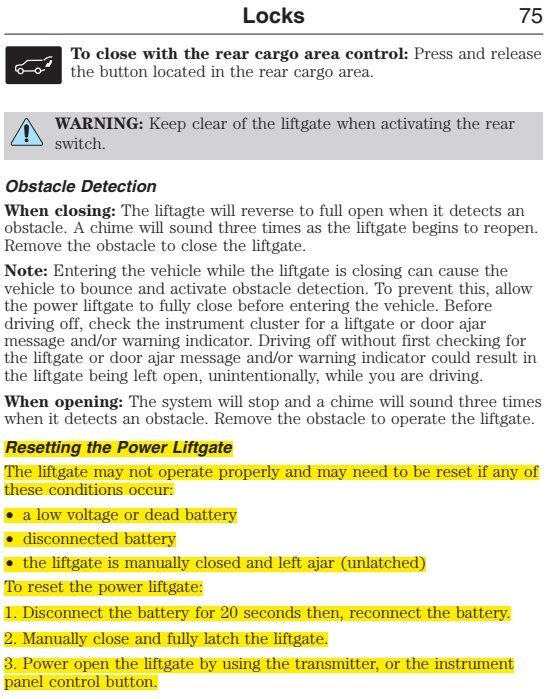
As @enigma-2 indicates, with us looking to the 2013 Edge Owners Guide pictured below (with relevant text highlighted in yellow )...
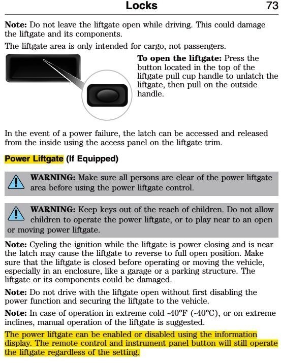

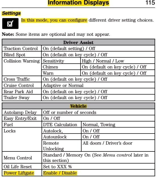
However, before you disable your Edge's power liftgate, you may want to perform a Power Liftgate Reset to see if it eliminates the partial-opening issue...
 ion
ion
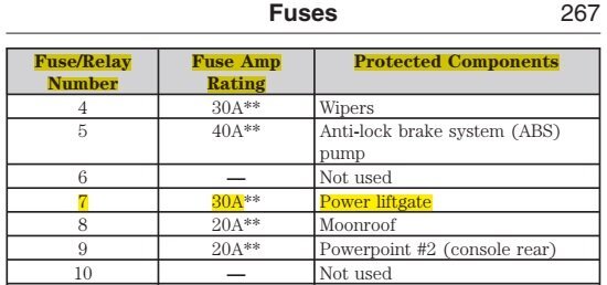
But, rather than disconnecting the vehicle's battery to perform the Reset, removing the Fuse #7 in the Power Distribution Box for 20 seconds fully performs the Power Liftgate Reset and it only affects the Power Liftgate circuit...
Side-2013EdgeOwnersGuide.jpg.8f163a4d159b030774af4db951c11c6b.jpg)
Please consider reporting back here on what effect the Power Liftgate Reset has upon the partial opening issue.
Other diagnostic steps are available if the Power Liftgate Reset procedure provides no improvement.
Or, you can disable the Power Liftgate, per your original question.
Good luck!
-
3
-
-
Welcome to the Forum @Bunky!
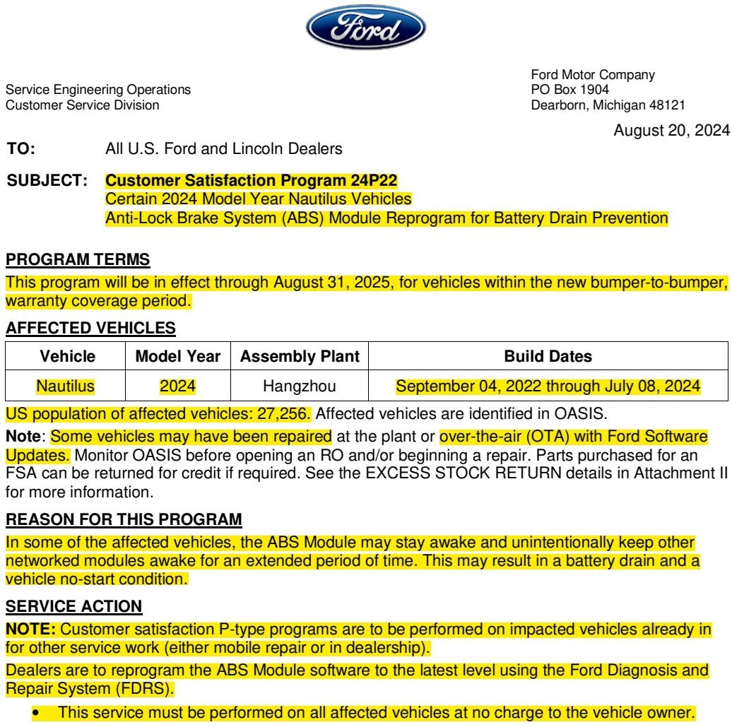
If you've not already reviewed them, clicking on this Search Link will provide a list of posts in this Recalls, TSBs & Warranty forum that may apply to your 2024 Nautilus.
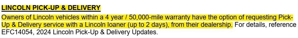
If any of these issues are affecting your 2024 Nautilus, you should discuss them with your dealer and -- where any software updates are indicated as resolving the issues -- encourage your dealer to utilize the Dealer Software Support Hotline (DSSH) experts to resolve your 2024 Nautilus' issues.
Good luck!
-
1
-
-
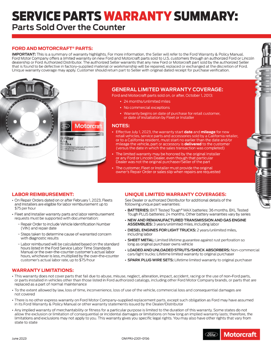
@Eric in California: Ford and Motorcraft replacement parts carry a 24-month/unlimited mileage warranty, which includes labor cost...

Print the below-attached PDF document and take it with you to the Ford dealership that installed the now-faulty replacement camera -- if that action occurred within the 24-month warranty period.
Good luck!
-
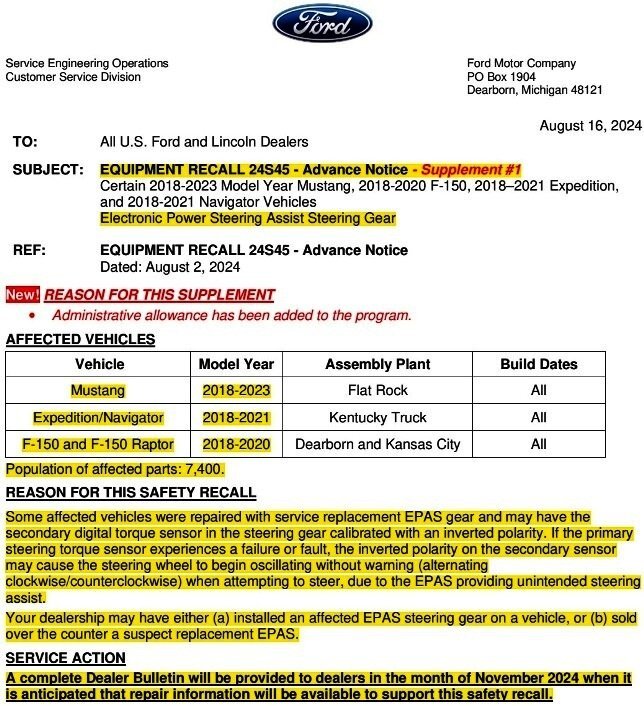
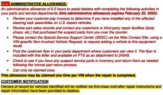
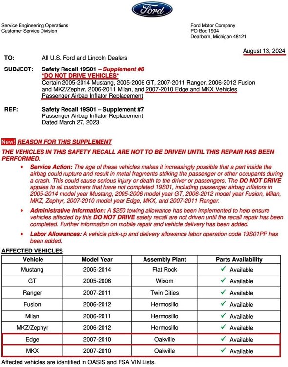
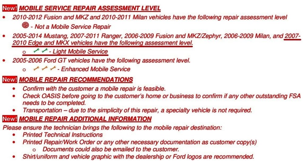
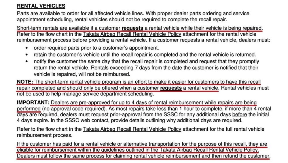
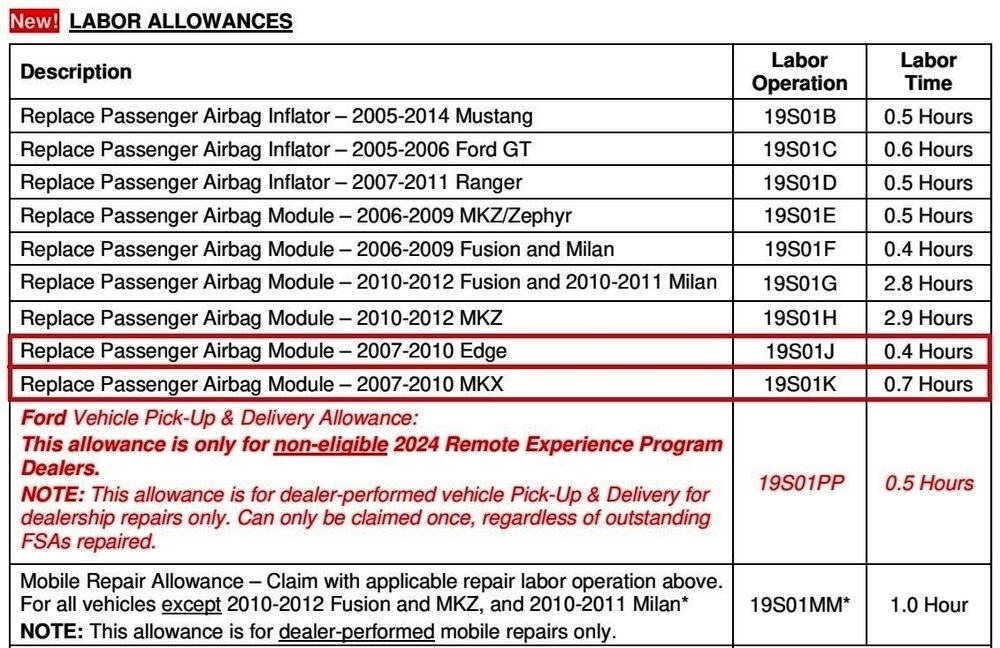
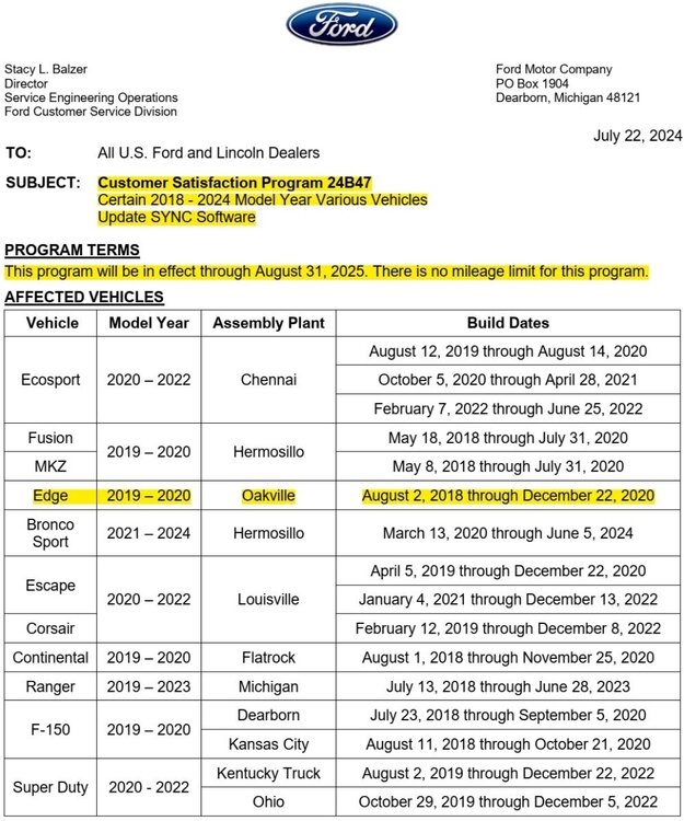
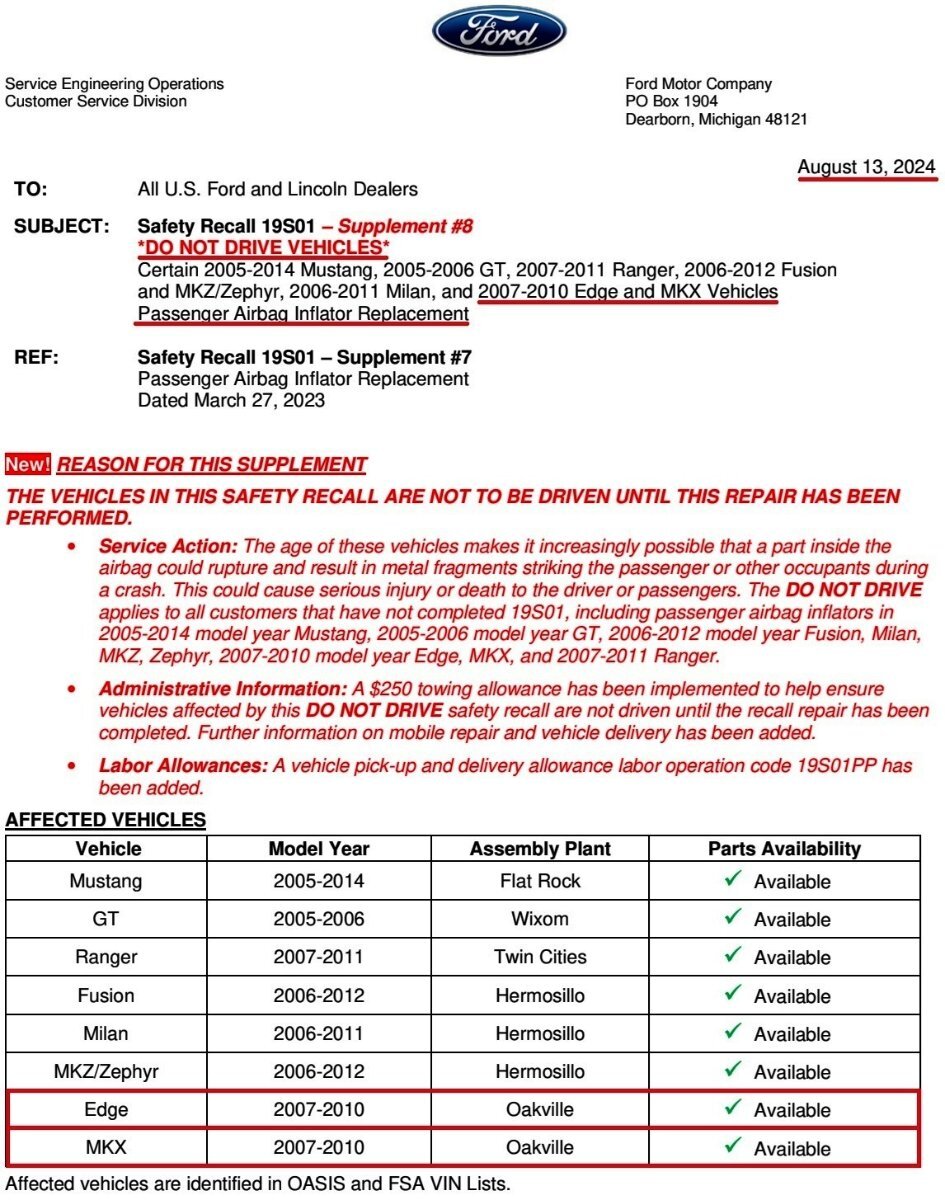
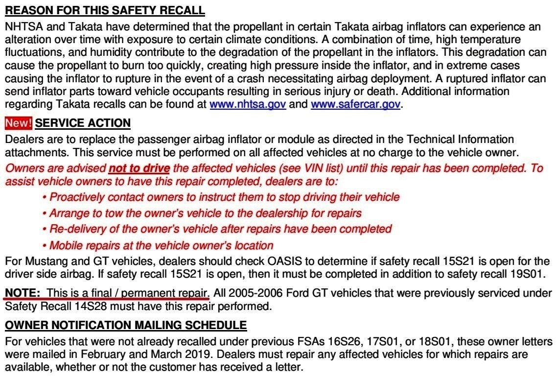
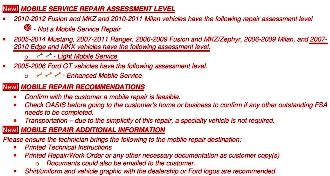
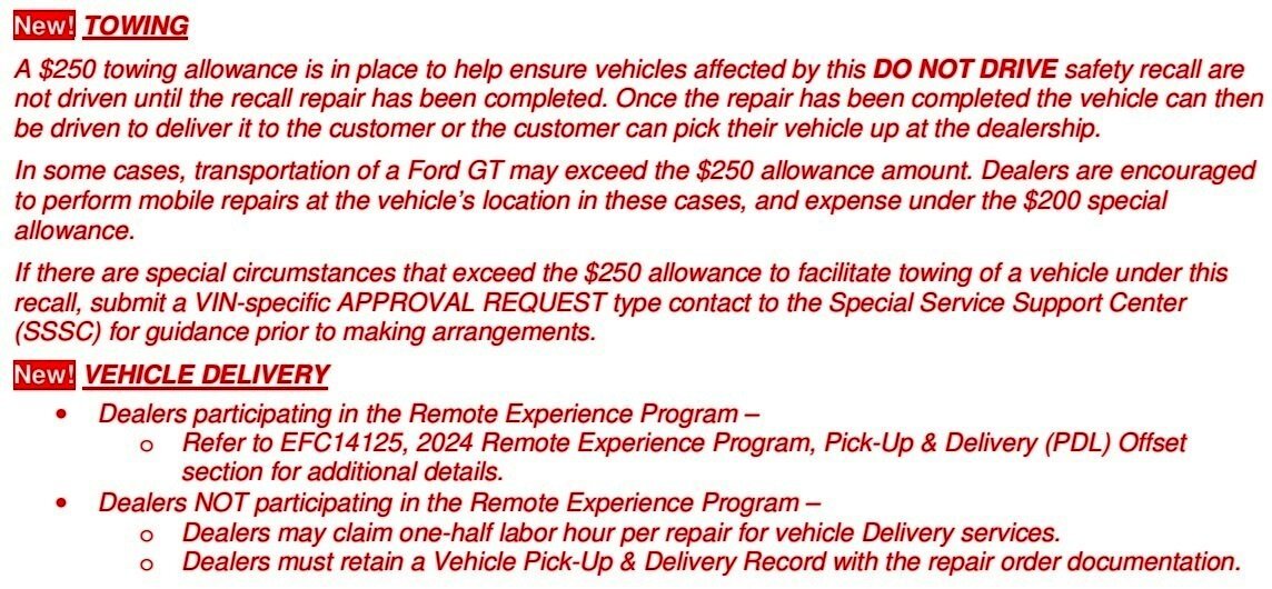
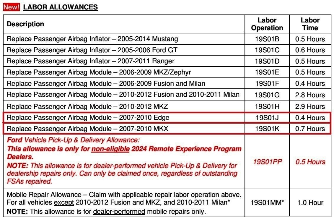
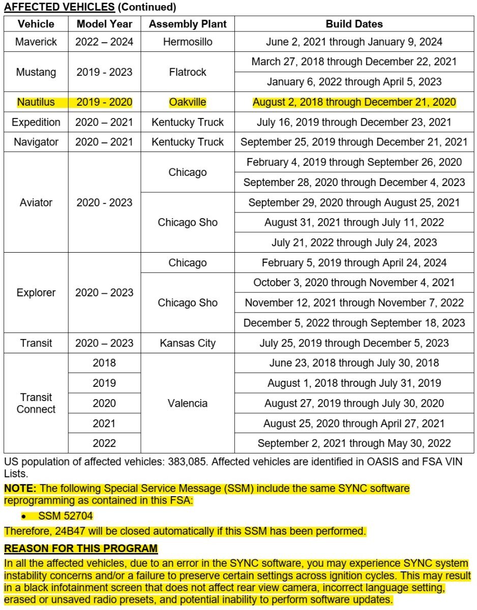
From this latest Dealer Bulletin, regarding affected vehicles which have not had their originally installed passenger airbag inflator replaced under Safety Recall 19S01:
REASON FOR THIS SUPPLEMENT - THE VEHICLES IN THIS SAFETY RECALL ARE NOT TO BE DRIVEN UNTIL THIS REPAIR HAS BEEN PERFORMED.
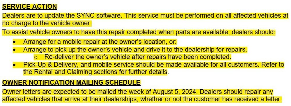
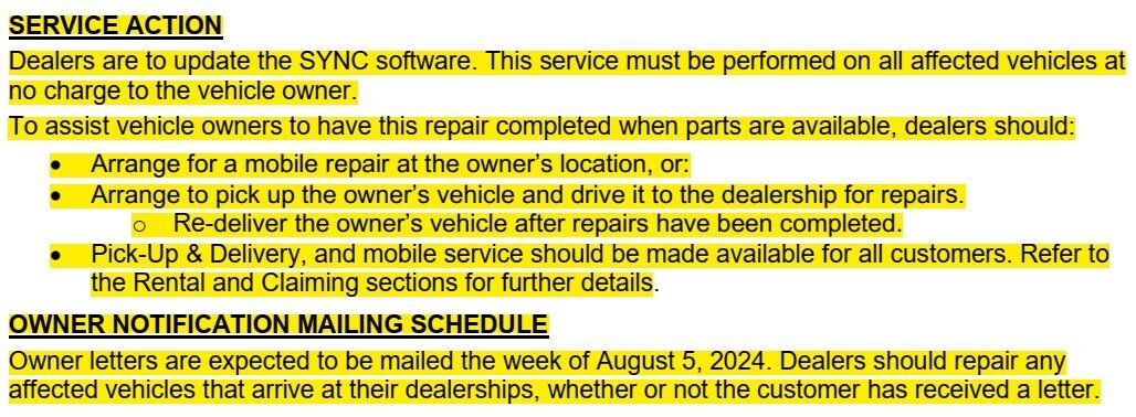
Service Action
The age of these vehicles makes it increasingly possible that a part inside the airbag could rupture and result in metal fragments striking the passenger or other occupants during a crash. This could cause serious injury or death to the driver or passengers.
The DO NOT DRIVE applies to all customers that have not completed 19S01, including passenger airbag inflators in
- 2005-2014 model year Mustang,
- 2005-2006 model year GT,
- 2006-2012 model year Fusion, Milan,MKZ, Zephyr,
- 2007-2010 model year Edge, MKX, and
- 2007-2011 Ranger.
Some portions of the below document sections have been underlined for Forum emphasis.
Red-colored text is done by Ford to indicate new and important content.
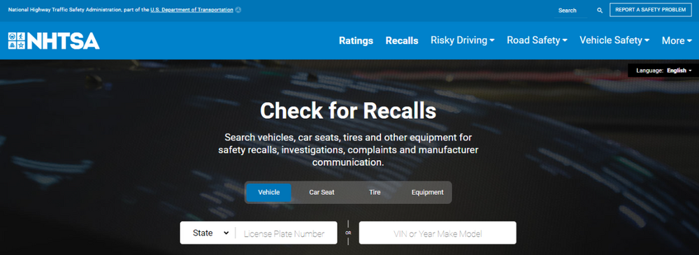
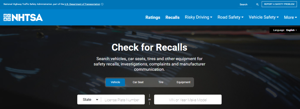
If you're unsure your 2007-2010 Edge/MKX passenger airbag inflator has already been replaced under Safety Recall 19S01, contact any Ford/Lincoln dealership Service department and they can search your vehicle's VIN in OASIS to determine if this DO NOT Drive directive applies to your vehicle. Or, alternatively, you can enter your vehicle's VIN into the NHTSA Recall website...


-
2
-
SSM 52797 - 2024 Nautilus - Audio Settings And Presets Will Not Save Some 2024 Nautilus vehicles may exhibit concerns with the last audio settings or audio presets not saving, audio system defaulting to AM radio, or memory seat settings not being retained. This may be due to the customer using a guest profile or inadvertently switching to a guest profile. Memory seat, audio presets, or last audio settings will not be retained when using a guest profile. Customers must set up a personnel profile and link the key fob and seat memory to a profile for these features/settings to remain in memory. Refer to the Personal Profiles section of the Owner Manual for further information. Customers may also be referred to the Lincoln YouTube Channel or Lincoln owners website for additional videos and information on how to use the features on their vehicle including how to set up a personal profile. -
1
-
-
From the 2019 Edge Workshop Manual...


DTC P0771, E clutch Does Not Apply symptom,
REFER to: E Clutch (307-01A Automatic Transmission - 8-Speed Automatic Transmission – 8F35/8F40, Diagnosis and Testing)


If either DTC P0771 or P0772 are set resolve them first. Otherwise, for DTC P2704,
REFER to: E Clutch (307-01A Automatic Transmission - 8-Speed Automatic Transmission – 8F35/8F40, Diagnosis and Testing).


The above-mentioned diagnostic procedures are attached below as PDF documents.
If your efforts progress to you needing electrical circuit & connector detail, I can provide that information.
If you elect to clear the DTCs and the Transmission Adaptive Tables, the Adaptive Learning Drive Cycle procedure is attached below...
Good luck!
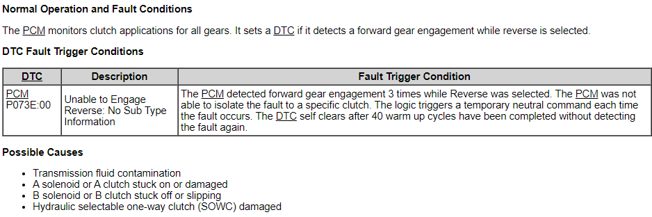
E Clutch - Diagnosis and Testing - 8F35-8F40 - 2019 Edge Workshop Manual.pdf E Clutch Description - Exploded View - 8F35-8F40 - 2019 Edge Workshop Manual.pdf Transmission Description - Disassembled Views - 8F35-8F40 - 2019 Edge Workshop Manual.pdf Diagnostic Pinpoint Test I - DTC P07E4 + Others - 8F35-8F40 - 2019 Edge Workshop Manual.pdf Diagnostic Pinpoint Test S - DTC P073E - 8F35-8F40 - 2019 Edge Workshop Manual.pdf Adaptive Learning Drive Cycle - 8F35-8F40 - General Procedures - 2019 Edge Workshop Manual.pdf
-
3
-
-
@EDST777: Attached below as PDF documents are relevant sections from the 2008 Edge Workshop Manual, which should be helpful if you decide to replace your Edge's Fuel Pump Module...
Good luck!
Fuel Tank and Filler Pipe — Exploded View - R&I ENHANCED IMAGE - 2008 Edge Workshop Manual.pdf Fuel Tank and Filler Pipe — Exploded View - Removal and Installation - 2008 Edge Workshop Manual.pdf Fuel Pump Module - Connector C463 Location - 2008 Edge.pdf Seat — Rear, 60 Percent - R & I ENHANCED IMAGE - 2008 Edge Workshop Manual.pdf Fuel Pump Module - Removal and Installation - 2008 Edge Workshop Manual.pdf Fuel Tank Locking Ring Wrench - Rotunda.pdf Quick Connect Coupling - General Procedures - 2008 Edge Workshop Manual.pdf Seat — Rear, 60 Percent - Removal and Installation - 2008 Edge Workshop Manual.pdf Seat — Rear, 40 Percent - R & I ENHANCED IMAGE - 2008 Edge Workshop Manual.pdf Seat — Rear, 40 Percent - Removal and Installation - 2008 Edge Workshop Manual.pdf Fuel Level Sender - Removal and Installation - 2008 Edge Workshop Manual.pdf Fuel System Pressure Release - General Procedures - 2008 Edge Workshop Manual.pdf Rear Quarter Interior Trim Panel - Removal and Installation - 2008 Edge Workshop Manual.pdf
-
1
-
-
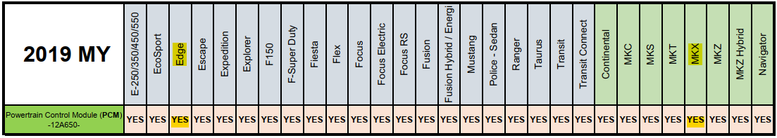
The Dealer Software Support Hotline (DSSH) is enforcing the reporting of unique Repair Validation Codes (RVC) to ensure appropriate diagnostics are being conducted before the removal and replacement of certain modules is authorized.
With yellow-highlight added, to emphasize text in Edge/Nautilus/MKX columns...
Announcing the Dealer Software Support Hotline (DSSH) Update
Always use the PTS Diagnostics Tab and Workshop Manual to determine the correct diagnostic for your vehicle concern. Modules in this chart require you to use the following process:
If you are required to submit a Technical Support Request (TSR) to the DSSH you must do this prior to module removal.
NOTE: This Chart will be updated frequently to keep you informed of policy changes regarding module replacements. Be sure to check here often; a PTS What's New will be released with each updated chart.

-
3
-
-
SSM 52788 - 2023-2024 Escape/Corsair, 2024 Nautilus - All Wheel Drive (AWD) - Various AWD/4WD/4x4 Warning Messages Displayed In The Message Center With Loss Of AWD Function - Diagnostic Trouble Codes (DTCs) C0095, C05D9:74, P060A, P060B, P060C, And/Or P1674 Some 2023-2024 Escape/Corsair, 2024 Nautilus vehicles may exhibit various AWD/4WD/4x4 warning messages displayed in the message center with loss of AWD function for the remainder of the active key cycle. DTCs C0095, C05D9:74, P060A, P060B, P060C, and/or P1674 may be stored in the AWD module. This condition may be due to the software in the AWD module. To correct the condition, reprogram the AWD module using the latest software level of the Ford Diagnosis and Repair System (FDRS) scan tool. Clear DTCs after programming is complete. Start the vehicle and place the vehicle into drive (D) for at least 45 seconds, then back into park (P). Recheck for DTCs and if no DTCs are present in the AWD module, the repair is complete. If any DTCs return, follow the applicable diagnostic pinpoint test (PPT) steps found in Workshop Manual (WSM), Section 307-07A to correct the condition. For claiming use casual part 7P238 and applicable labor times in Section 10 of the Service Labor Time Standards (SLTS) Manual. -
From the 2022 Edge Workshop Manual, with emphasis added...
Sport Mode
In S mode the transmission selects the optimum gear for best performance. This gear selection is typically lower than that of drive (D) and the shifts are faster. For vehicles equipped with steering wheel paddle switches (SelectShift™), selecting sport mode allows the driver to change gears up or down.
S mode provides:
- Additional slope, engine braking and extends lower gear operation to enhance performance for uphill climbs, hilly terrain or mountainous areas. This can increase engine RPM during engine braking.
- Additional lower gear operation through the automatic transmission shift strategy.
- Quicker gear selection and at higher engine speeds.
Good luck!
-
5
-
SSM 52773 2023-2024 F-150/Escape/Explorer/Maverick, 2024 Nautilus - FHEV - DTCs P0A7D And/Or P0DE6 And VIN Is Not Recognized By High Voltage Battery Rescue Charger 2023-2024 F-150/Escape/Explorer/Maverick and 2024 Nautilus vehicles equipped with a full hybrid electric vehicle (FHEV) powertrain may exhibit diagnostic trouble codes (DTCs) P0A7D and/or P0DE6 and the vehicle identification number (VIN) is not recognized by the Midtronics xRC-3363 High Voltage Battery Rescue Charger. This may be due to the software level of the Midtronics xRC-3363 High Voltage Battery Rescue Charger. To correct this condition, update the Midtronics xRC-3363 High Voltage Battery Rescue Charger to the latest software level by navigating to the Main Menu > Settings > About (i) then selecting the download button in the bottom right corner of the tool's screen. SSM 52774 - 2020-2024 Escape/Explorer, 2021-2024 F-150, 2022-2024 Maverick And 2024 Nautilus - FHEV - Low Voltage Cable Connection Issue With The High Voltage Battery Rescue Charger Some 2020-2024 Escape/Explorer, 2021-2024 F-150, 2022-2024 Maverick and 2024 Nautilus vehicles equipped with a full hybrid electric vehicle (FHEV) powertrain may exhibit a cable connection error screen from the Midtronics xRC-3363 High Voltage Battery Rescue Charger. The xRC-3363 will prompt the technician to verify the low voltage connections when no actual fault is present. This may be due to the software level of the Midtronics xRC-3363 High Voltage Battery Rescue Charger. To correct this condition, update the Midtronics xRC-3363 High Voltage Battery Rescue Charger to the latest software level by navigating to the Main Menu > Settings > About (i) then selecting the download button in the bottom right corner of the tool's screen. 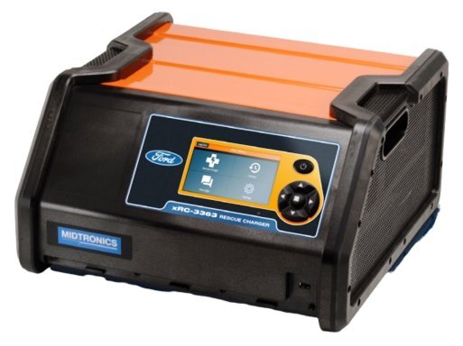
According to Midtronics, manufacturer of the above-referenced High Voltage Battery Rescue Charger...
Rescue charge in hybrid vehicles is performed when a High Voltage battery state of charge is too low to turn over the engine, a common scenario when technicians are working to diagnose vehicle issues. The xRC-3363 acts as a jump start to recharge the HV battery to a point where it can turn over the engine. These extra crank attempts allow technicians to identify issues so the vehicle can be repaired and returned to the road.
For anyone interested interested in the technical and operational details of this device, its User's Guide is attached below as a PDF document...
-
1
-
-
Ford is adding 2025 Aviator to the affected models list, reinforcing the Service Community's awareness of this issue two weeks after releasing SSM 52724...
SSM 52760 - 2024 Nautilus, 2025 Explorer/Aviator/Police Interceptor Utility - Right (Passenger) Exterior Mirror Does Not Unfold After The Vehicle Is Unlocked Some 2024 Nautilus and 2025 Explorer/Aviator/Police Interceptor Utility vehicles may exhibit a symptom where the vehicle's right (passenger) exterior mirror does not come out of the folded position after the vehicle is unlocked. This may be due to a software concern within the driver's door module (DDM) and passenger's door module (PDM). If the mirror unfolds after pressing the mirror fold button in the vehicle twice, inform customers that they can continue to drive the vehicle and engineering is currently working on a solution for this condition that is expected in Q4 2024. Replacement or reprogramming of the DDM and PDM will not resolve this condition at this time. Monitor OASIS for additional information and schedule service appointments for customers once the repair becomes available. If the mirror does not unfold after pressing the mirror fold button in the vehicle twice, refer to Workshop Manual (WSM), Section 501-09 for further diagnostics. -
1
-
-
The scope of the Dealer Software Support Hotline is being expanded to responding to 2021 & 2022 and 2023 & 2024 Model Year vehicles with SYNC-related concerns.
The Hotline will also serve as a resource to technicians experiencing challenges with Customer Satisfaction Program 24B47.
-
4
-
-

The referred-to Special Service Message 52704 was previously posted to the Forum in relation to establishment of the Dealer Software Support (DSSH) Hotline...
SSM 52704 2019-2024 Various Vehicles - SYNC 3 - Accessory Protocol Interface Module (APIM) Programming Error - "INSTL_ERR12" Using FDRS Or Stuck On "Updating System Software" Or No Response From The Vehicle When Using The Universal USB Updater Some 2019-2024 vehicles equipped with SYNC 3 may experience a programming Error - "INSTL_ERR12" while programming APIM using the Ford Diagnosis and Repair System (FDRS) or experience a frozen screen which says "updating system software" or no progress/response from module using the universal USB updater. This may be due to low memory in the APIM commonly occurring on software level NU5T-14G381-AB/BB. The current software level can be verified in the SYNC tab of Professional Technician System (PTS) or using the vehicle's center display screen, Settings > General > About. To correct the condition, run the universal USB updater. If unsuccessful, using the latest software version of the FDRS scan tool, run the service function "APIM - Reset the Accessory Protocol Interface Module Application" and select "Clear All User Data" option. The center display screen will reboot. As soon as the vehicle's center display screen displays the boot up logo, immediately reinsert the same universal serial bus (USB) drive that was utilized during the prior failed programming attempt. The vehicle's center display screen should display "successful APIM update" when complete. If process does not complete as expected, retry no more than one time. If the concern persists, then raise a Technical Support Request for assistance. Do not replace the APIM prior to contacting Technical Support. -
3
-
-
Welcome to the Forum @Mystifyu!
2015 Edge Blower Motor resources are attached below as PDF documents...
Good luck!
Blower Motor - Removal and Installation - 2015 Edge Workshop Manual.pdf Blower Motor Speed Control - Removal and Installation - 2015 Edge Workshop Manual.pdf Climate Control System - Vehicles With DATC - System Operation and Component Description - 2015 Edge Workshop Manual.pdf Blower Motor - Wiring Diagram - 2015 Edge.pdf Battery Junction Box (BJB) - Illustration Showing Blower Motor Relay Location - 2015 Edge.pdf Battery Junction Box (BJB) - Illustration Showing Location - 2015 Edge.pdf
-
1
-
-
SSM 52730 - 2023-2024 F-Super Duty And 2024 F-150/Nautilus - Diagnostic Trouble Code (DTC) U211B:51 Stored In The TCU After Software Update Or An OTA Some 2023-2024 F-Super Duty and 2024 F-150/Nautilus vehicles may set DTC U211B:51 in the telematics control unit (TCU) module after a software update on the TCU is performed at dealer or via over the air (OTA) Update. The DTC U211B:51 in the TCU has no effect on vehicle functionality or connectivity. Replacement or reprogramming of the TCU will not resolve this condition. DTC U211B:51 should be ignored if no other DTCs are present in the TCU and no symptoms present. No further service action is required. -
1
-


flashing brake and yellow lights for electronic parking brake
in Brakes, Chassis & Suspension
Posted · Edited by Haz
Welcome to the Forum, @JImBushMiller!
Information from the 2018 Edge Workshop Manual...
Placing your device cursor over underlined acronyms may yield full-words pop-up descriptions of the acronyms.
Parking Brake and Actuation
The ABS module monitors and controls the parking brake system. The ABS module sends a reference voltage to the parking brake switch. When the driver moves the parking brake switch to the APPLY position, the reference voltage is sent back to the ABS module indicating an APPLY request. The ABS module then determines from sensor inputs if the parking brakes can be applied and sends voltage to the parking brake actuator motors. Once the parking brakes are fully applied, the ABS module sends a message to the IPC which illuminates the red BRAKE warning indicator. If the red BRAKE warning indicator is already illuminated due to a non-parking brake concern, the IPC displays PARK BRAKE APPLIED in the message center. When the driver moves the parking brake switch to the RELEASE position, the reference voltage is sent back to the ABS module indicating a RELEASE request. The ABS module then determines from sensor inputs and CAN messages (ignition state and brake pedal input) if the parking brakes can be released and sends voltage to the parking brake actuator motors. Once the parking brakes are fully released, the ABS module sends a message to the IPC which extinguishes the red BRAKE warning indicator. If the red BRAKE warning indicator cannot be extinguished due to a non-parking brake concern, the IPC displays PARK BRAKE RELEASED in the message center.
Red Brake Warning Indicator
The red BRAKE warning indicator notifies the driver of hydraulic brake concerns, some ABS concerns and parking brake application. When a hydraulic brake or ABS concern is present, the warning indicator illuminates solidly. After the parking brakes are fully applied, the red BRAKE warning indicator illuminates and remains illuminated as long as the ignition is set to ON. If the ignition is set to OFF after the parking brakes are applied or if the parking brakes are applied after the ignition is set to OFF the red BRAKE warning indicator illuminates for 10 seconds and is then extinguished.
Yellow Parking Brake Indicator
The yellow parking brake indicator is used in conjunction with the message center to notify the driver of parking brake system concerns. When a concern or DTC is present, the indicator illuminates and a message is displayed in the message center. The yellow parking brake indicator also illuminates when the parking brake system is in service mode.
Anti-Lock Brake System (ABS) Module
The ABS module is attached directly to the HCU and is the electronic control unit for the parking brake system. The ABS module monitors all switch inputs, sensor inputs and HS-CAN messages relating to the parking brake system, then directly controls the parking brake actuator motors. The ABS module also sets Diagnostic Trouble Codes (DTCs) in the event that a system or component failure should occur.
Parking Brake Actuator Motor
The parking brake actuator motors are single speed reversible electric motors mounted on the rear brake calipers. The motors can be serviced separately from the calipers.
Parking Brake Switch
The parking brake switch is a 3 position switch with 2 sets of 3 internal micro switches, one set is for APPLY and one set is for RELEASE. The 3 switch positions are APPLY (pulled up), NEUTRAL (at rest or static) and RELEASE (pushed down).
Whenever the parking brake switch is disconnected and then reconnected, a DTC sets in the ABS module and the ABS module disables the parking brake system. To restore parking brake system functionality and to clear the DTC , the parking brake switch must be moved through all 3 positions twice within 5 seconds pausing for approximately one-half second when the switch is in the NEUTRAL position between each apply and release.
As the above Symptom Chart directs, you should have your Edge's electronic modules scanned to see if any Diagnostic Trouble Codes (DTCs) are revealed, especially in the vehicle's ABS module.
If you don't have access to a diagnostic scan tool, contact a local national-brand auto parts store to determine if personnel there can scan the Edge for you.
If the scan tool reveals any DTCs, please make note of them or take a smartphone photo of the scanner screen showing the results.
Depending upon what triggered the DTC, clearing DTCs after documenting all that exist, may take care of the problem.
If not, then report the DTC code(s) here for further guidance.
Are you a do-it-yourself Edge owner who will try repairing this issue yourself, or might you prefer to have a dealership or independent mechanic address this issue for you?
Good luck!