Haz
-
Posts
1,568 -
Joined
-
Last visited
-
Days Won
436
Content Type
Profiles
Forums
Gallery
Everything posted by Haz
-
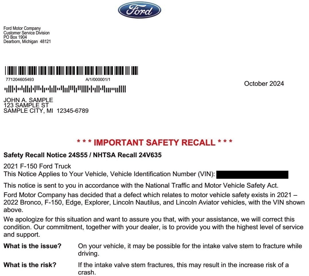
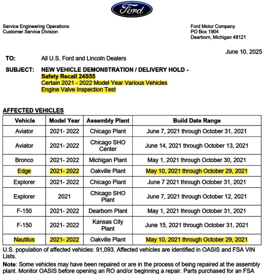
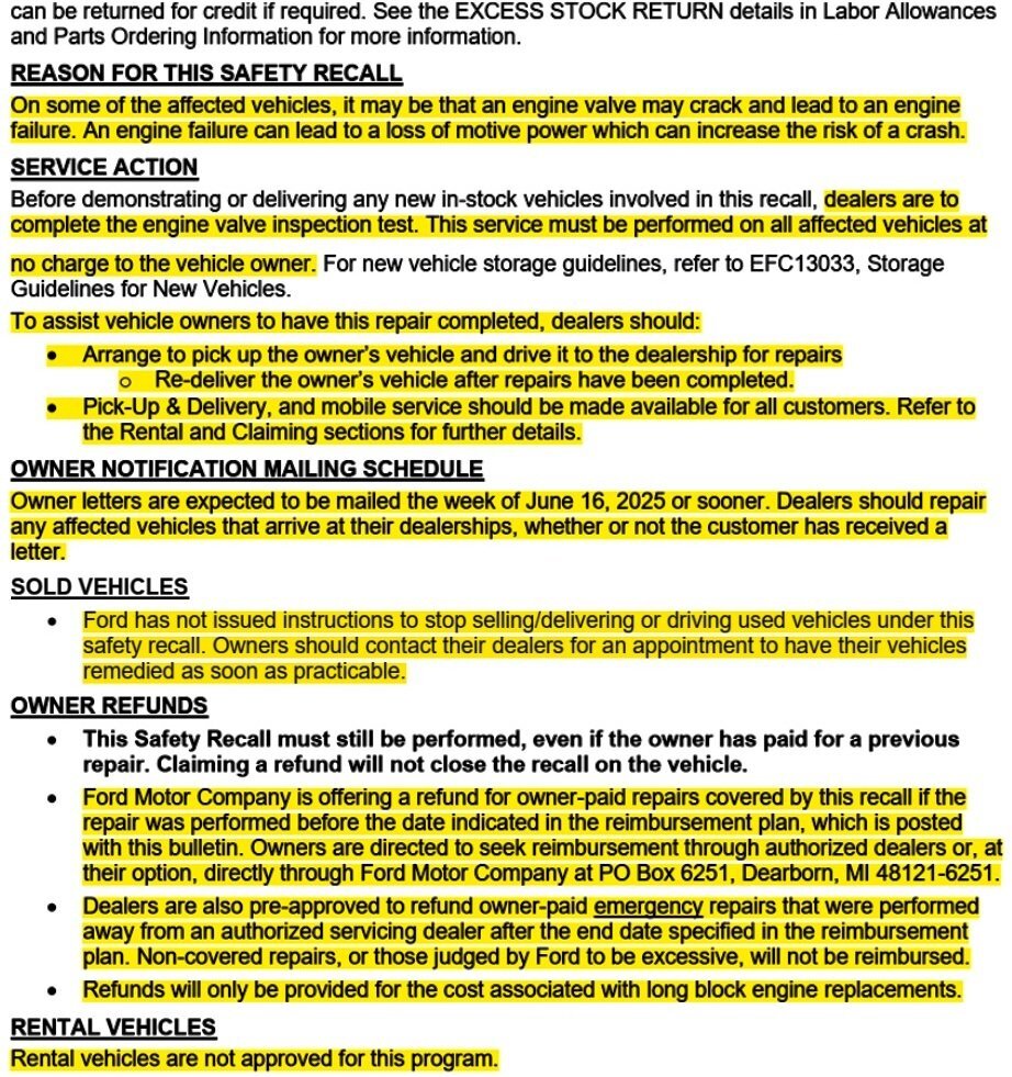
Safety Recall 24S55 - 2021-2022 Edge ST/Nautilus - 2.7L EcoBoost - 05-10-2021 through 10-29-2021 Build Dates + Other Models - Engine Valve Inspection Test (Initially Electronic, then Running with Restart), Failure Leads To Engine Long Block Replacement
Haz replied to Haz's topic in Recalls, TSBs & Warranty
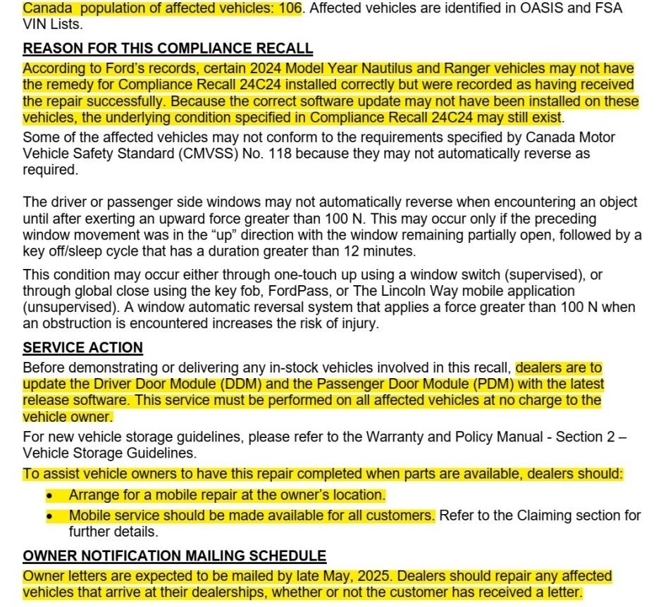
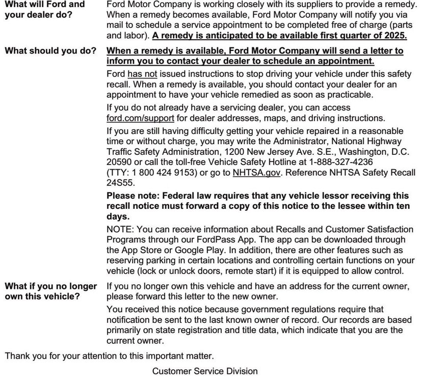
@Davidoo: You are recalling correctly! In October 2023, the National Highway Transportation Safety Administration (NHTSA) upgrading their investigation into this topic was posted to the Forum here... NHTSA Investigation Upgraded To Engineering Analysis Phase, Applies To 2.7L & 3.0L EcoBoost Engines, Vehicle Population Includes 2021-2022 Edge (6,889), and 2021-2022 Lincoln Nautilus (8,596) + Other Models The NHTSA website now offers this Chronology Report that details the 'anatomy' of Safety Recall 24S55... CERTAIN 2021 and 2022 MY FORD/LINCOLN VEHICLES – NANO INTAKE VALVE Date of Submission: August 23, 2024 Chronology of Defect / Noncompliance Determination Provide the chronology of events leading up to the defect decision or test data for the noncompliance decision. On January 25, 2022, Global CCRG opened an investigation into 2021 Model Year (MY) Lincoln Aviator and Nautilus vehicles equipped with 2.7L and 3.0L Nano EcoBoost gasoline engines after an international investigation discovered twenty-two (22) instances of engine failure at three (3) months in service or less. A review of failed engines revealed that the engine intake valves fractured and fell into the combustion chamber of the engine causing catastrophic engine damage leading to a Loss of Motive Power (LOMP). Based on an analysis of returned fractured valves from failed engines, Ford identified that the potential root cause of the failures was engine intake valve failure due to valves that exceeded the designed specification for hardness, were brittle, and more likely to fracture. Ford determined that this was due to the supplier’s grinding processes and the sensitivity of the intake valve material to grinding processes that were not within control specifications. The intake valve material was changed for vehicles produced after October 31, 2021. The new material increased the valve’s robustness to keeper groove grinding processes outside of control specifications. On May 05, 2022, Ford’s North America (NA) CCRG opened an investigation regarding early time in-service left-hand engine intake valve fractures on 2021MY Ford and Lincoln vehicles equipped with 2.7L and 3.0L Nano EcoBoost gasoline engines. Teardown analysis of returned failed engines confirmed intake valve fracture on two-hundred fifty-one (251) engines from warranty repairs. On May 27, 2022, the National Highway Traffic Safety Administration (NHTSA) opened Defect Petition 22-001 in response to an increasing trend of Vehicle Owner Questionnaires (VOQs) submitted by 2021MY Ford Bronco customers alleging LOMP as a result of catastrophic engine damage. On July 22, 2022, NHTSA opened Preliminary Evaluation (PE) 22-007 to continue their investigation into 2021MY Ford Bronco customer allegations of LOMP. Ford’s response was provided to NHTSA on September 28, 2022. On September 29, 2023, NHTSA opened Engineering Analysis (EA) 23-002 and expanded the scope of their investigation to include all 2021 and 2022MY Ford/Lincoln products that are equipped with the 2.7L and 3.0L Nano EcoBoost engines. Ford’s response was provided to NHTSA on January 02, 2024. Ford noted that there was a higher than ambient level of repairs observed for vehicles produced between May 1 and October 31, 2021. On December 4, 2023, NHTSA personnel visited Ford facilities to observe Ford’s engine teardown and laboratory analysis processes for evaluating fractured intake valves. Between February and August 2024, Ford has participated in several discussions related to fractured intake valves on Nano EcoBoost engines with NHTSA. As of August 09, 2024, Ford is aware of 811 global warranty claims confirmed or suspected to be related to fractured intake valves with report dates ranging from February 13, 2021 to June 03, 2024. Ford is aware of 267 field reports with report dates of October 06, 2020 to October 18, 2023. Ford is aware of 223 customer reports with report dates of March 31, 2021 to August 29, 2023. On August 16, 2024, Ford’s Field Review Committee reviewed the concern and approved a field action. Ford is not aware of any reports of accident or injury related to this condition. Affected owners received an initial notification letter in October 2024... An earlier NHTSA letter on Safety Recall 24S55 was posted to the Forum here. Good luck!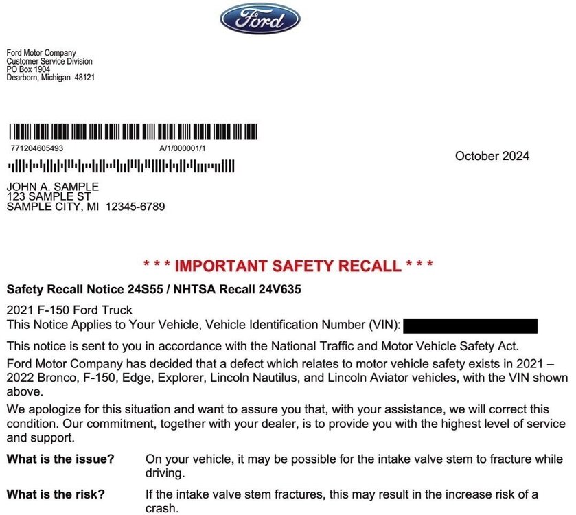
-
@Wubster100: Happy to see @TXFRDOwner satisfying your shared informational needs. Good luck!
-
Safety Recall 24S55 - 2021-2022 Edge ST/Nautilus - 2.7L EcoBoost - 05-10-2021 through 10-29-2021 Build Dates + Other Models - Engine Valve Inspection Test (Initially Electronic, then Running with Restart), Failure Leads To Engine Long Block Replacement
Haz replied to Haz's topic in Recalls, TSBs & Warranty
@omar302: Per Ford's Service Labor Times Standards, you are correct... A half-hour contingency is apparently being added to the SLTS allowance for Safety Recall 24S55. Good luck!


-
*** The following Dealer Bulletin has been edited to provide the information most relevant to Forum members. *** The complete Safety Recall 24S55 Technical Instructions document, which provides Testing and Service procedures for professional technicians, is attached at the bottom as a PDF document... Safety Recall 24S55 - Engine Valve Inspection Test - Technical Instructions.pdf


-
@m4rioo: As @1004ron describes, when a Ford Service outlet in Poland enters your Edge's VIN in OASIS via the Poland edition of the Professional Technician System (PTS) website, the Warning Messages immediately inform them that your Edge is a USA-market vehicle... ...and while Emissions Recall 24E09 shows among Outstanding Field Service Actions, OASIS provides no information on 24E09 on the Poland OASIS/PTS website, meaning the Recall is not applicable in your region, so I do not expect that a properly configured (for Europe/Poland) FRDS would provide the update -- but that's not necessarily a bad thing. The PCM update provided under 24E09 involves false (incorrect) indications of Catalyst performance that would indicate the indicated Catalyst needs replacement. Now, I'm unsure whether Emissions Testing in Poland/Europe relies upon OBD/electronic data to provide a Pass/Fail rating, but in the event that your Edge throws the DTC indicating a need for Catalyst replacement -- if available in your area -- you could have the Catalyst effectiveness verified by getting a "sniffer" tailpipe-inserted probe/sensor test to verify if the Catalyst performance is in compliance with your country/regional standards, or if Emissions standards or testing requirements don't apply, you'll at least know via a "sniffer" tailpipe Emissions test the Catalyst's authentic condition -- if your Edge ever does throw a DTC saying your Edge's Catalyst is performing in a sub-standard manner, which it may never do. On the other shown Outstanding Field Service Action -- Safety Recall 25S49 -- that is Europe-active and Poland OASIS/PTS provides the following information... 25S49 - Cross Carline: Rear View Camera (RVC) Software Update - Vehicle Hold Date Published: 20 May 2025 Confidential Reference:25S49 Subject: Cross Carline: Rear View Camera (RVC) Software Update -- Vehicle Hold Special Attention: The Recall Co-ordinator should have overall responsibility for implementing this action within your Dealership and Retail Dealer(s). Introduction In some of the affected vehicles, the rear-view camera may not work as intended. Customers may experience a frozen screen, followed by a black screen and a system reboot. Service Instructions are under development and will be released as soon as possible. In the meantime, NEW vehicles (irrespective if sold, unsold, registered or unregistered) must not be released to customers. These vehicles must be held and not sold or used for demonstration purposes until further instructions are published. Vehicles Affected Affected vehicles will be identified on OASIS. Model/Variant Assembly Plant Affected Build Periods (inclusive dates) from to Transit Courier -- Craiova 7/7/2023 30/9/2024 Mach-E -- Cuautitlan 17/3/2020 15/12/2023 F-150 -- Dearborn 8/1/2020 16/4/2024 F-150 -- Dearborn 14/10/2021 15/12/2023 Mustang -- Flatrock Assembly Plant - USA (AAGCL) 4/10/2022 15/2/2024 F-150 -- Kansas City 23/6/2020 9/6/2023 F-250 -- Kentucky 23/3/2022 6/11/2024 Transit -- Kocaeli 4/10/2021 7/3/2025 Bronco -- Michigan Truck 30/9/2020 10/5/2024 Edge -- Oakville 19/8/2020 3/5/2024 Ranger -- Pacheco Assembly 25/10/2022 19/12/2024 Everest -- RAYONG ASSEMBLY PLANT-THAILAND (AAGCM) 1/12/2021 29/2/2024 Ranger -- RAYONG ASSEMBLY PLANT-THAILAND (AAGCM) 26/4/2022 28/5/2024 Focus -- Saarlouis 21/7/2021 21/1/2025 Ranger -- Silverton 24/5/2022 16/11/2024 Ranger -- Thailand LTD Plant Build (AAGB7) 1/10/2022 6/4/2024 Kuga -- Valencia 15/9/2023 15/9/2023 Transit Custom -- Yenikoy 18/1/2023 14/4/2025 Dealer action These vehicles must be held and not sold until further instructions are published. So, Ford Service outlets there have only been provided this early notification on 25S49, but nothing can be done until the repair procedures are developed and made available to them. You could check in with them, in a calm & cordial manner to see if -- since 25S49 is active in Poland -- your USA-market Edge might be eligible -- though, you may run into that same barrier of "It's a USA-market vehicle and not eligible". Good luck!

-
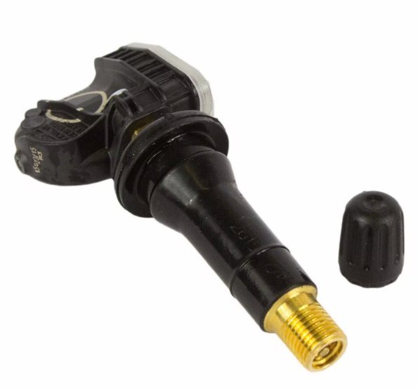
@m4rioo: If you're curious about the meaning of the various markings on TPMS sensors, see... General Service Bulletin 25-7012 - Tire Pressure Monitoring Systems (TPMS) Identification Glad to hear your question is not due to any TPMS malfunction. Please let us know what brand/model of wheels & winter tires you eventually decide upon. Good luck!
-
SSM 53890 - 2024-2025 Nautilus, 2025 Aviator - 12 Channel Audio Digital Signal Processing Module (DSP) - No Audio/Sound And/Or Replacement DSP Will Not Program Some 2024-2025 Nautilus and 2025 Aviator vehicles equipped with a 12 channel DSP (minor feature code IDBAV for Nautilus or IDBBJ for Aviator) may exhibit a no audio/sound concern or programmable module installation (PMI) incomplete on a replacement DSP. To confirm a vehicle is built with a certain minor feature code, review the build information by double-clicking the vehicle identification number (VIN) in the upper left corner in the Professional Technician System (PTS). This concern may be due to software in the DSP. For vehicles with a no sound concern, reprogram the DSP using the latest software level of the Ford Diagnosis and Repair System (FDRS) scan tool. If the no sound concern continues, refer to Workshop Manual, Section 415-00 for further diagnosis. For error messages during PMI of a replacement DSP, attempt PMI again using the latest software level of the FDRS scan tool. For claiming, use causal part 18B849 and labor operations 12651D and 12651D4.
-
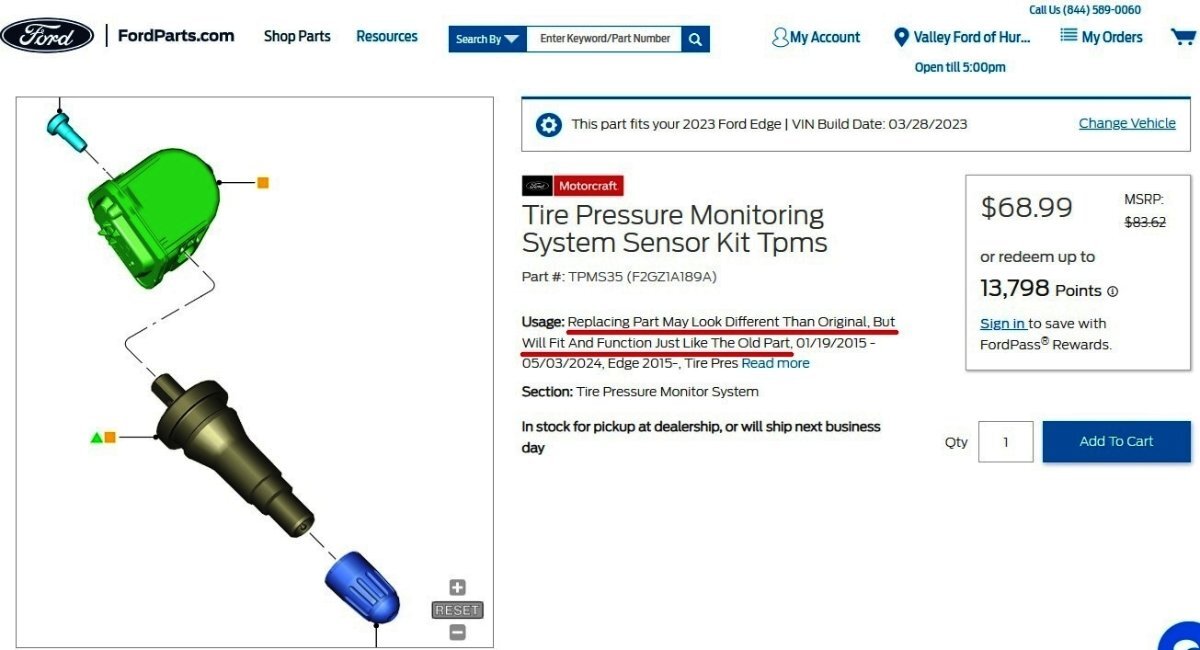
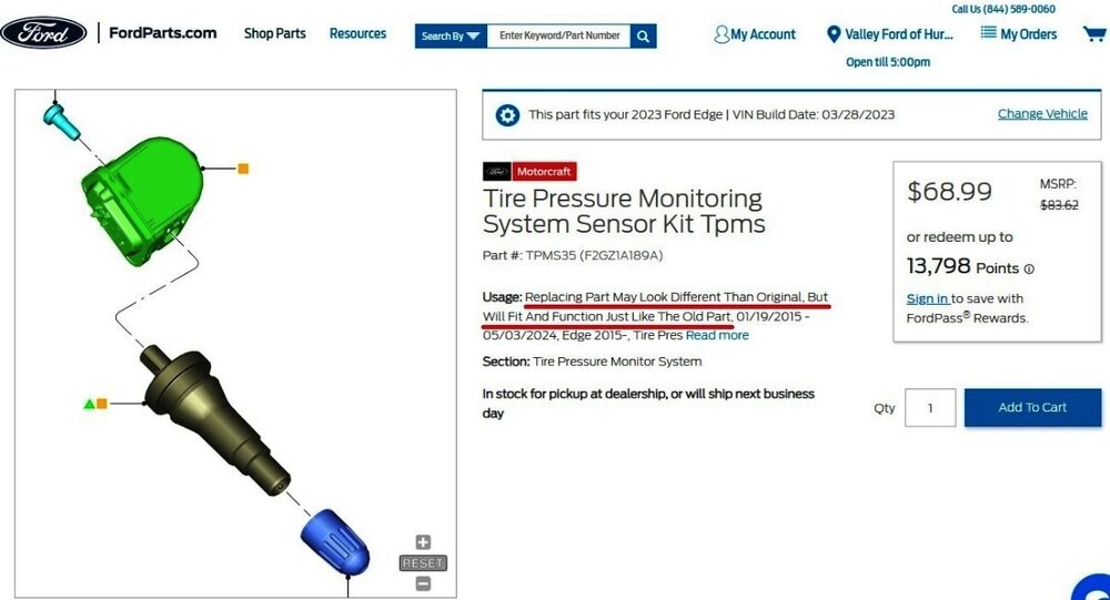
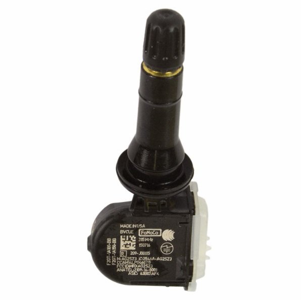
@m4rioo: Ford OASIS info for your Edge's VIN confirms 315 MHz... VIN-based TPMS sensor search from Ford's online parts-selling site... Radio frequency interference can negatively impact TPM systems, per the 2022-2024 Edge Workshop Manual, included below and more fully covered in the attached PDF documents... Placing your device cursor over underlined acronyms may yield popup full-words descriptions of the acronyms. Radio Frequency Interference (RFI) RFI can be caused by: Video equipment has been found to cause RFI especially when the video and power supply lines are near the TPMS . Anti-theft alarms (even those installed by the dealership) have been found to create enough RFI to cause the TPMS to malfunction or lose considerable range. These anti-theft alarms can be difficult to locate, as they are usually hidden somewhere out of the way for reduced accessibility. Many in-vehicle cell phone chargers have been found to cause considerable RFI . The vehicles with the power point closest to the RTM are the most affected. It must be noted that most cell phone chargers do not produce high levels of RFI all the time. This depends on the state of charge of the cell phone battery. The phone battery must be almost completely discharged in some cases. Power supplies and DC / AC inverters typically create a lot of RFI . Most consumer grade equipment has very little filtering or shielding. Using Hit Rate Parameter Identifiers (PIDs) to Determine the Presence of RFI If an intermittent RFI issue is suspected, the information contained in the last 5 TPMS warning event Parameter Identifiers (PIDs) can be combined with specific Parameter Identifiers (PIDs) from the BCM to determine which TPMS sensors are being affected and if a RFI source is currently present in the vehicle. The BCM module contains Parameter Identifiers (PIDs) used to keep track of the number of TPMS messages received from the 4 trained TPMS sensors. These Parameter Identifiers (PIDs) can provide insight on the performance of the TPMS , and can help establish the presence of an Frequency Interference (RFI) source. TPM_HITS_LF (Tire Pressure Monitor Hit Rate Left Front) – The number of TPMS messages received by the BCM module from the LH front sensor TPM_HITS_RF (Tire Pressure Monitor Hit Rate Right Front) – The number of TPMS messages received by the BCM module from the RH front sensor. TPM_HITS_LRO (Tire Pressure Monitor Hit Rate Left Rear Outer) – The number of TPMS messages received by the BCM module from the LH rear sensor TPM_HITS_RRO (Tire Pressure Monitor Hit Rate Right Rear Outer) – The number of TPMS messages received by the BCM module from the RH rear sensor. Method for determining if a RFI issue has been affecting the TPMS : Collect the last 5 TPMS events and determine if they were due to system faults or low tire air pressure. Collect the TPMS Hit Rate PID counters and compare them to the last 5 TPMS events. If the TPMS Hit Rate PID counters are significantly different from each other or if the locations with lower hit rate values show up as fault locations in last 5 TPMS events and BCM DTC B124D:02 (Tire Pressure Sensor: General Signal Failure) is present, an intermittent RFI source is most likely preventing the signals from these TPMS sensors from reaching the BCM . An intermittent RFI source can also be the case when all 4 TPMS sensors show up in the last 5 fault events and BCM DTC B1182:00 (Tire Pressure Monitoring System (TPMS): No Sub Type Information) is present. The possible cause would a strong source of RFI noise. Original Equipment Manufacturer (OEM) Modules In some cases the RFI may actually be caused by a module or ground on the vehicle. Depending on the severity of the concern, a dirty ground, improperly built ground shield or module can disable the system. Modules that have microcontrollers using clock circuits to create timing pulses for the microprocessor may radiate RFI . Using Customer Electronics to Pinpoint RFI This method can be a way to determine the cause of a concern before the sensors and module are replaced with little or no effect on system performance. Discuss with the customer what types of devices they were using when the event occurred. Determine which power points are being used and, if necessary, ask the devices be activated to determine their affect on the TPMS . Options for Eliminating Intermittent TPMS Operation Caused by RFI If an Original Equipment Manufacturer (OEM) component or customer device is causing a RFI concern, replace the device. If a phone charger is causing a RFI concern, the customer should consult with their cell phone provider to acquire a different battery charger. If a device such as a dealer installed anti-theft alarm is causing a RFI concern, move the device to another location in the vehicle. In the case of a portable device move the power cord to another power point location. In summary, if the RFI source is present and cannot be moved or replaced, the intermittent concern remains. The TPMS must accept the unwanted system operation the RFI can cause. Good luck! Tire Pressure Monitoring System (TPMS) - System Operation and Component Description - 2022-2024 Edge Workshop Manual.pdf Tire Pressure Monitoring System (TPMS) - Diagnosis and Testing - 2022-2024 Edge Workshop Manual.pdf

-
Adding Adaptive suspension to my ST
Haz replied to johnmarkp's topic in Brakes, Chassis & Suspension
@johnmarkp: Just noticed this and I don't believe I fulfilled it -- attached below as PDF document(s)... Good luck! Vehicle Dynamics Control Module (VDM) - Wiring Diagram - 2023 Nautilus.pdf REAR SHOCK ABSORBER SOLENOID VALVE LH - Connector C4044 Pinout Details - 2023 Nautilus.pdf -
@Bunky: The Special Service Message you cite also posted overnight to OASIS on the Professional Technician System (PTS) website... Historically, system/module resetting actions have been described in various terms, such as soft or cold rebooting, or master or hard resets. In the past, hard resets involved battery disconnects or fuse removals that produced the most drastic effects, by restoring factory default states that eliminated owner-added data, owner-configured features, and driving-learned module configurations. The 2024-2025 Nautilus Workshop Manual offers this description of reset effect on the Lincoln Digital Experience... Lincoln Digital Experience System Overview NOTE: Refer to the Owner Literature for additional details of the Lincoln Digital Experience. NOTE: It may be necessary on occasion to carry out a master reset of the system for correct operation. Accumulated data uploaded from devices may corrupt the module software and resetting the system clears this data to allow normal operation. This system is a hands-free communication and entertainment system and provides the following functions: Send and receive phone calls via a paired Bluetooth-enabled phone Send and receive text messages via a paired Bluetooth-enabled phone Connect media devices (such as an iPod®, USB device, or Bluetooth-enabled audio device to play audio files Initiate a 911 Assist or emergency assistance call if the airbags deploy Provide Vehicle Health Reports Provide a vehicle Wi-Fi hotspot (if equipped, cellular subscription required) Control smart devices using the cellular connection via an app (similar to using Alexa™ or Siri™) Provide feedback to Ford about some of the related systems Provide over the air software updates Not all features are supported with every phone/device. The vehicle owner can schedule the systems to update wirelessly. The vehicle cannot be started or driven during the update process. The update does not occur unless a time is specified in the settings. Refer to the Owner Literature for details to update the vehicle wirelessly. Some vehicles only have the option to enable or disable the Over The Air update feature. Other vehicles have the additional capability of selecting this update to occur vie the cellular signal or a Wi-Fi signal. When the automatic system update feature is enabled, an icon displays on the screen. Tapping the icon brings up prompts to update the vehicle. Once the update download and installation is complete, an ignition cycle must occur before the update becomes active. We'll have to wait for the Owner's Manual and Workshop Manual rewrites to gain full understanding of Hard Reset effects, or, you could perform the SSM-described procedure and report-back on its possible drastic and wide-reaching effects. I'd wait for the rewrites, instead of having to perform re-do's to the numerous personal configurations & settings that you've refined over time. Good luck!

-
Broken Upper Instrument Panel Storage Bin Button
Haz replied to giraffegeoff's topic in Interior, A.C., Heat, Interior Trim
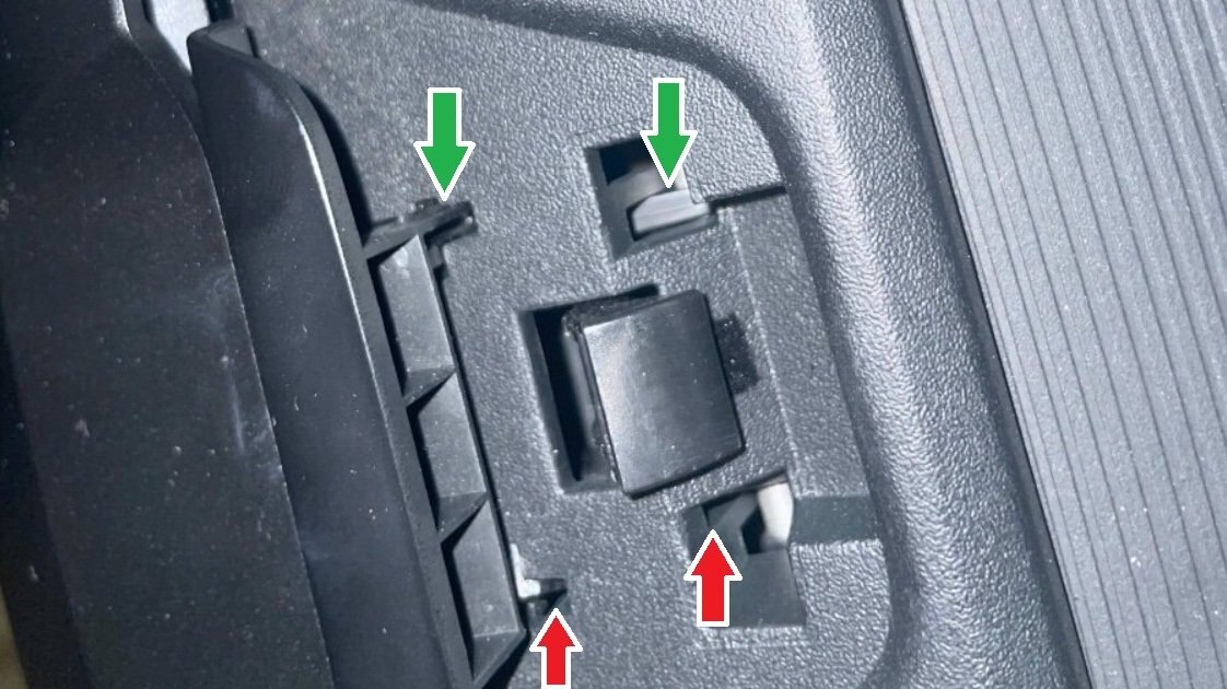
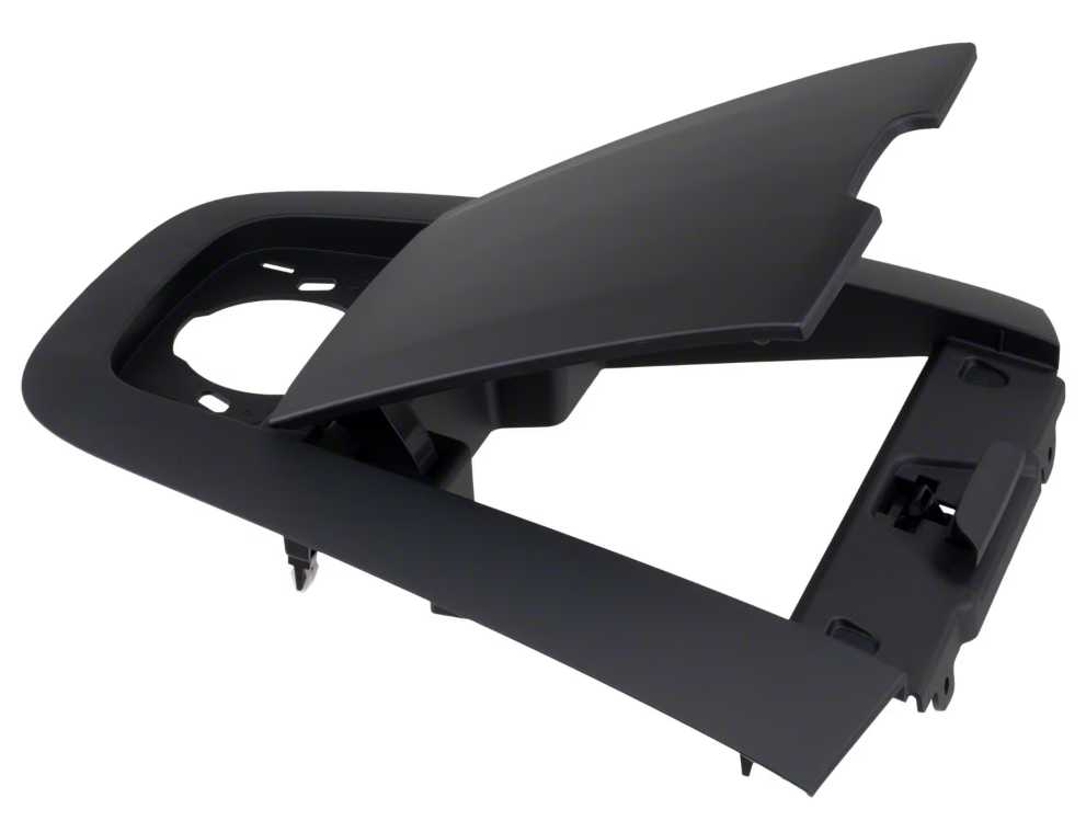
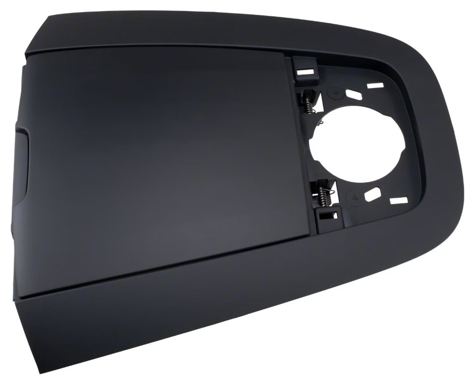
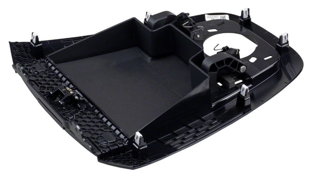
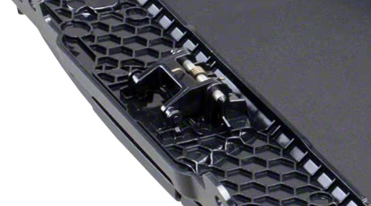
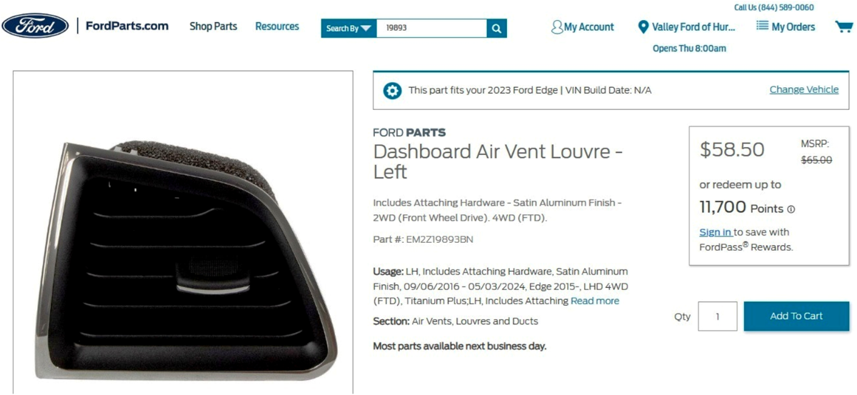
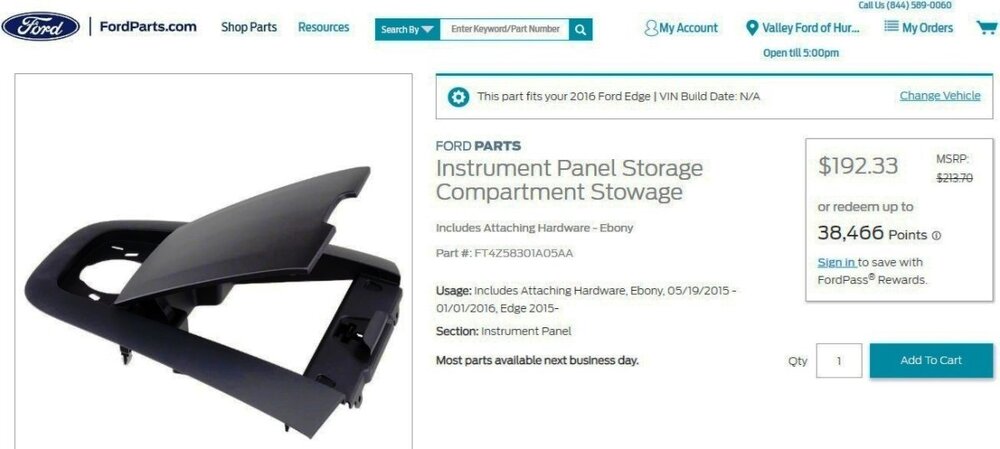
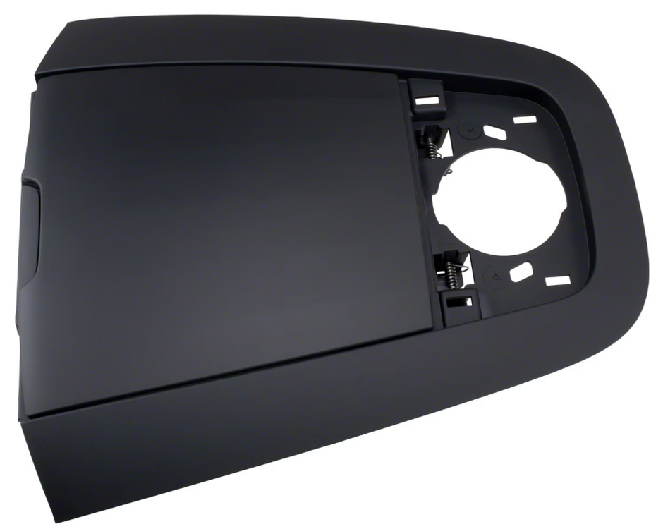
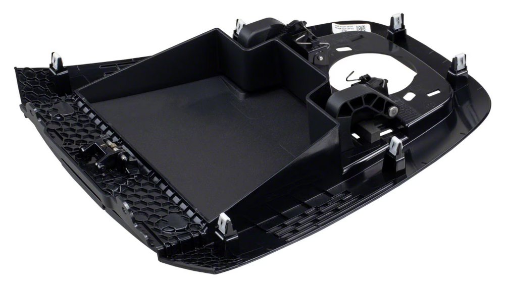
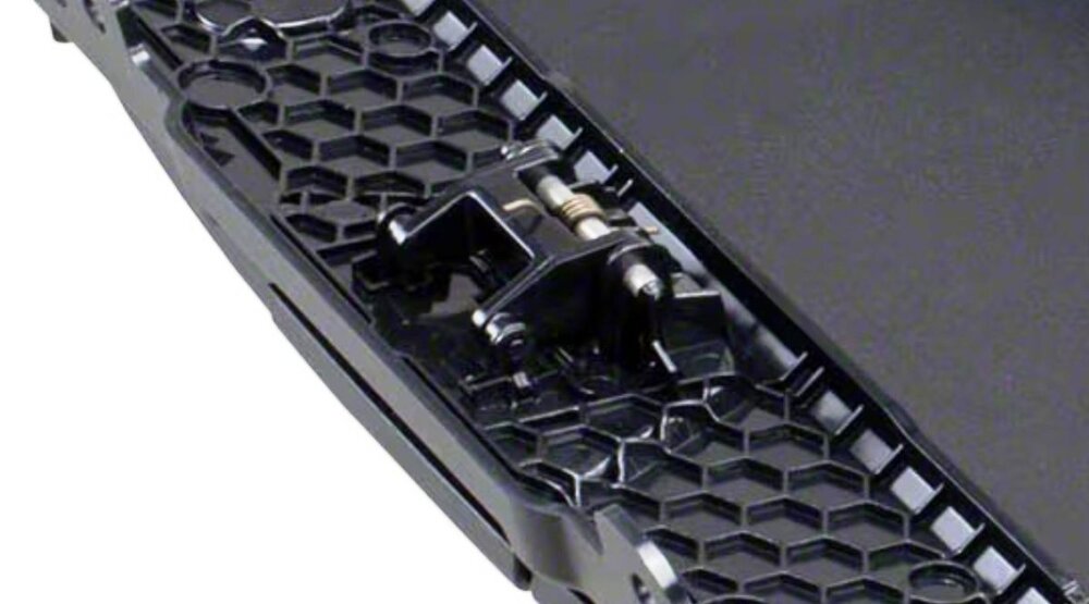
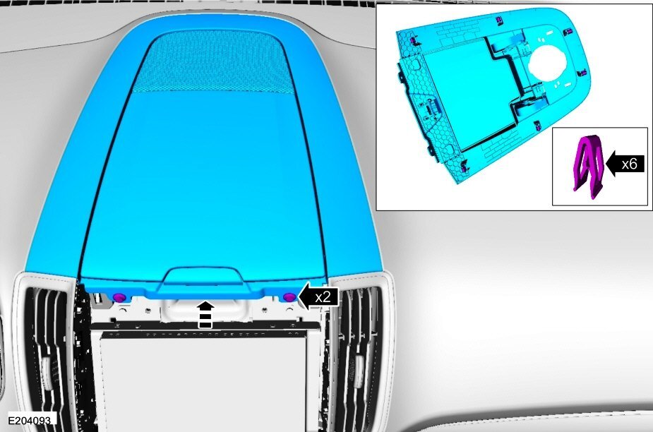
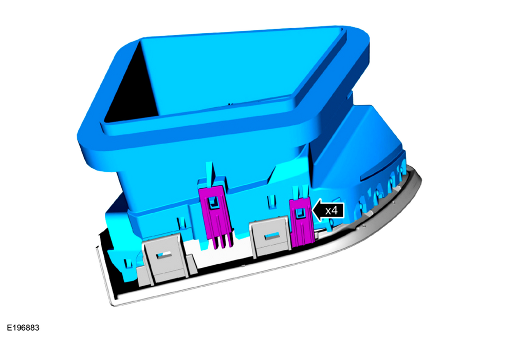
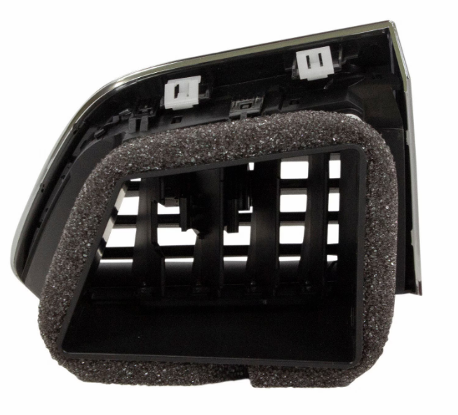
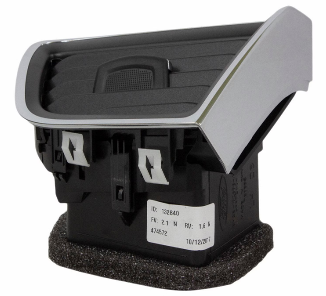
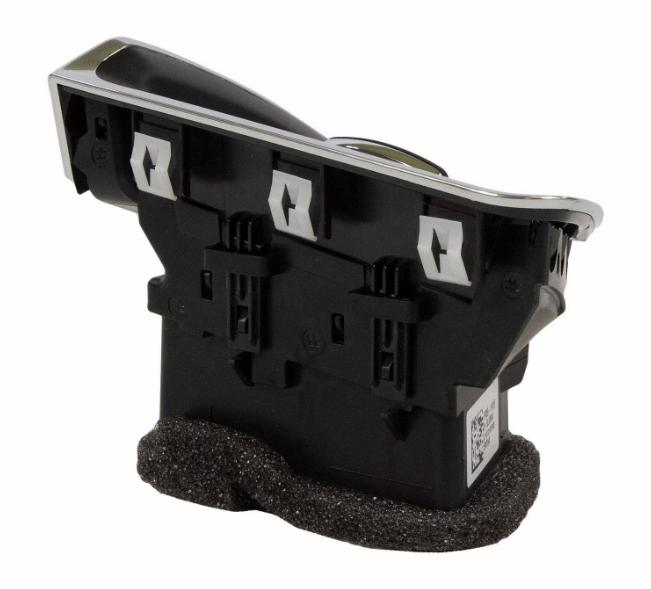
Welcome to the Forum, @giraffegeoff! Looking at your photo -- as you have no doubt already recognized -- there are clear visual differences between the red-arrowed side on which the unlatching button is sagging, and on the green-arrowed side where the unlatching button is not sagging... The plastic piece, pictured in your palm, likely broke away from the sagging-button-side, where it previously supported the button, and its rectangular stem passed through the red-arrowed voids to release the lid's latching mechanism. The button/latching mechanism is available only as Provided In Assembly (PIA), meaning that buying the entire storage compartment bin/lid assembly is required, if you wish to replace it. Ford's online parts-selling site offers several photos of the replacement part... Link to this FordParts webpage It's worth noting that the underside-view photo provides little detail of the button/latching mechanism, though it is possible an engineering improvement was made to the original mechanism design. The instrument panel storage bin lid assembly (FT4Z58301A05AA) is retained by two screws holding the audio speaker in place, and by two screws into the center stack... Accessing the two center-stack screws requires removing several adjacent components, as described in the two Workshop Manual sections that are attached below as PDF documents... Good luck! Front Controls Interface Module (FCIM) - Removal and Installation - 2016 Edge Workshop Manual.pdf Instrument Panel Upper Storage Bin Edit - Removal & Installation - 2016 Edge Workshop Manual.pdf

-
Welcome to the Forum, @fredo27! While I expect they are comparable where an individual pin is not called-out as being model-specific, attached below as PDF documents are Powertrain Control Module (PCM) connector pinout diagrams and a connectors-location illustration pulled for the 2007 MKX... Good luck! POWERTRAIN CONTROL MODULE (PCM) - Connector C175B Pinout Diagram - 2007 MKX Wiring Resource.pdf POWERTRAIN CONTROL MODULE (PCM) - Connector C175E Pinout Diagram - 2007 MKX Wiring Resource.pdf POWERTRAIN CONTROL MODULE (PCM) - Connector C175T Pinout Diagram - 2007 MKX Wiring Resource.pdf POWERTRAIN CONTROL MODULE (PCM) - Connector C175B + C175E + C175T Locations - 2007 MKX Wiring Resource.pdf
-
2023 ST Drivers side LH window Air Vent Removal
Haz replied to Jetboy47's topic in Interior, A.C., Heat, Interior Trim
@Jetboy47's Apple-device images converted for Forum viewing...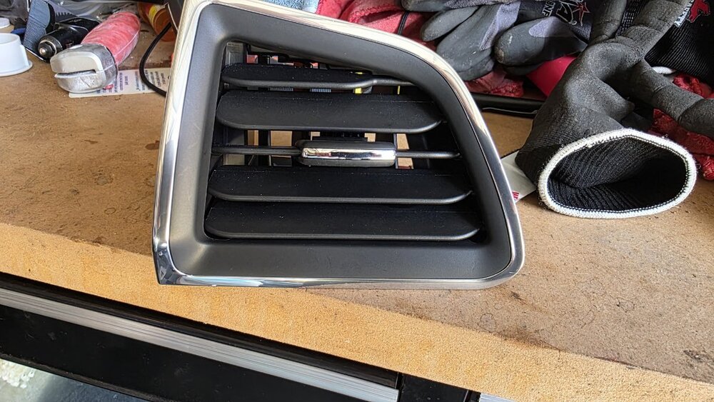


-
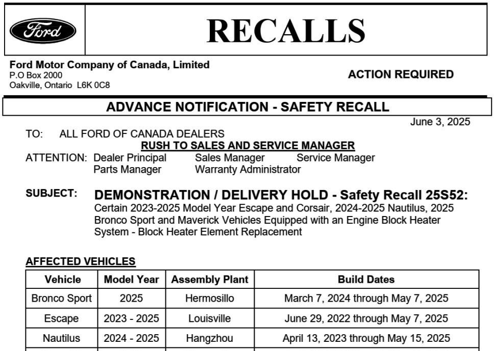
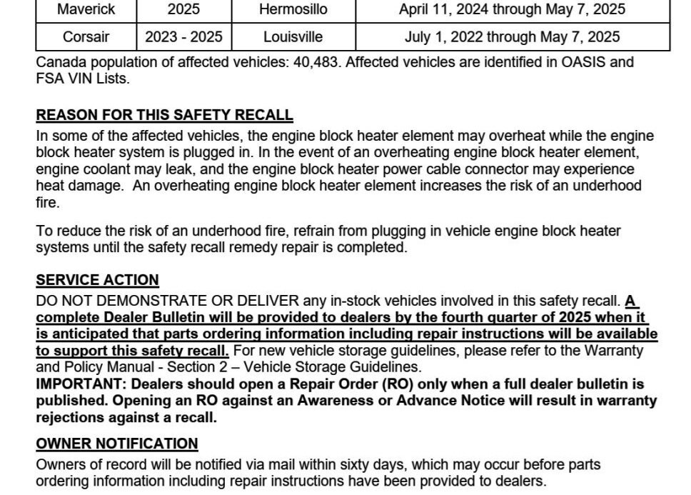
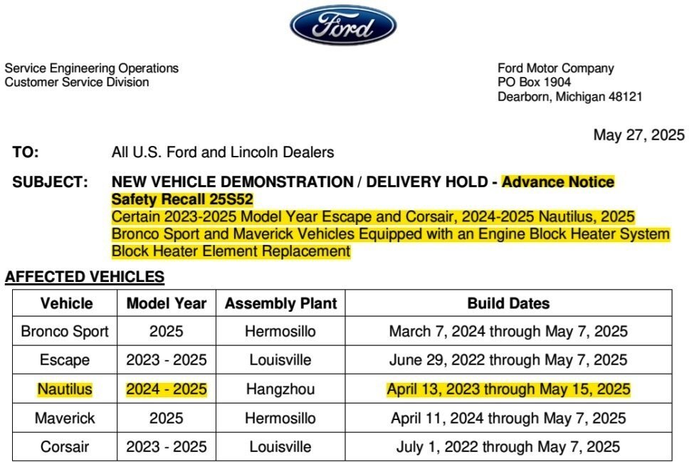
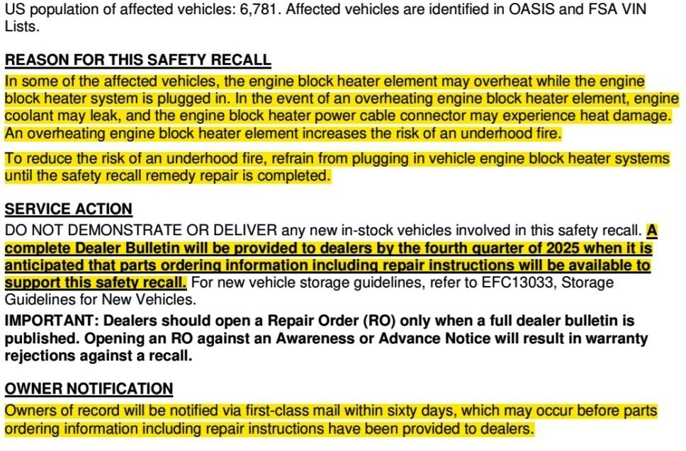
Confirming Ford of Canada's participation in Safety Recall 25S52...
-
I expect a Mobile Service technician would be able to fulfill the APIM update at your home/place of employment, or, vehicle Pickup & Delivery with a Lincoln loaner by the dealer will be among your options -- unless your dealer has really enjoyable Customer Waiting Room coffee. Good luck!
-
@Wubster100: I expect the risk of the X could be that those model years of those model lines are no longer supported with updates... Good luck!
-
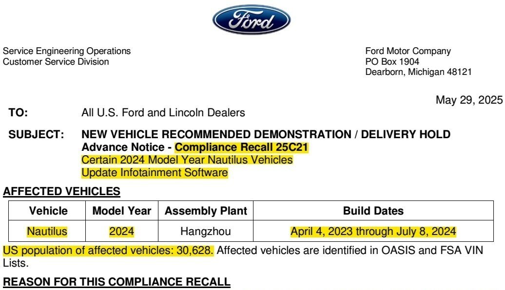
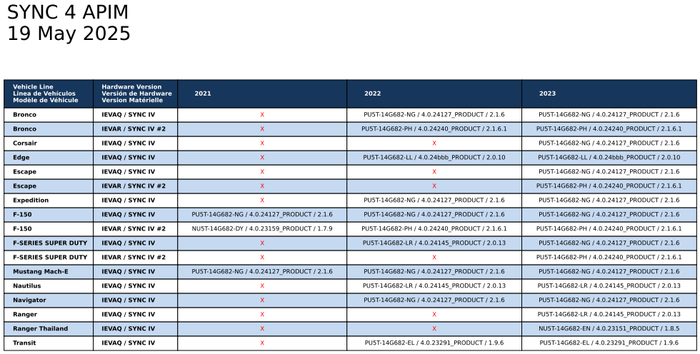
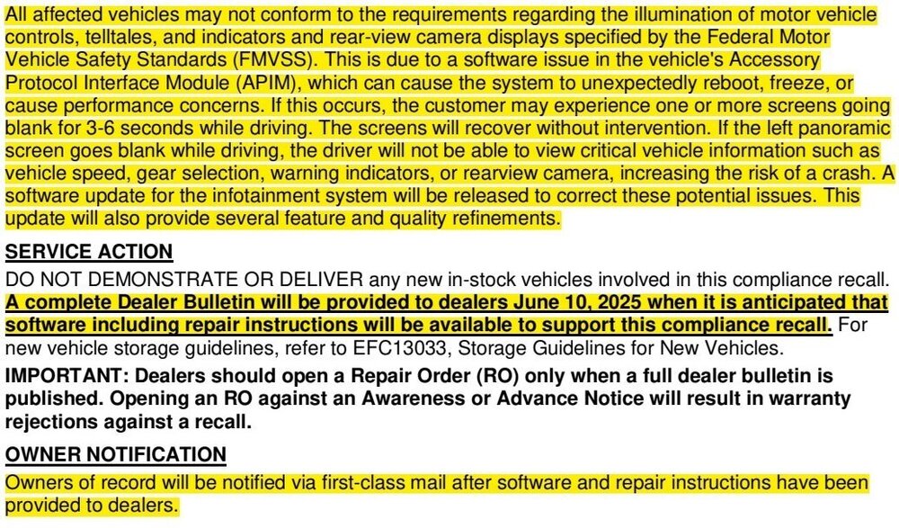
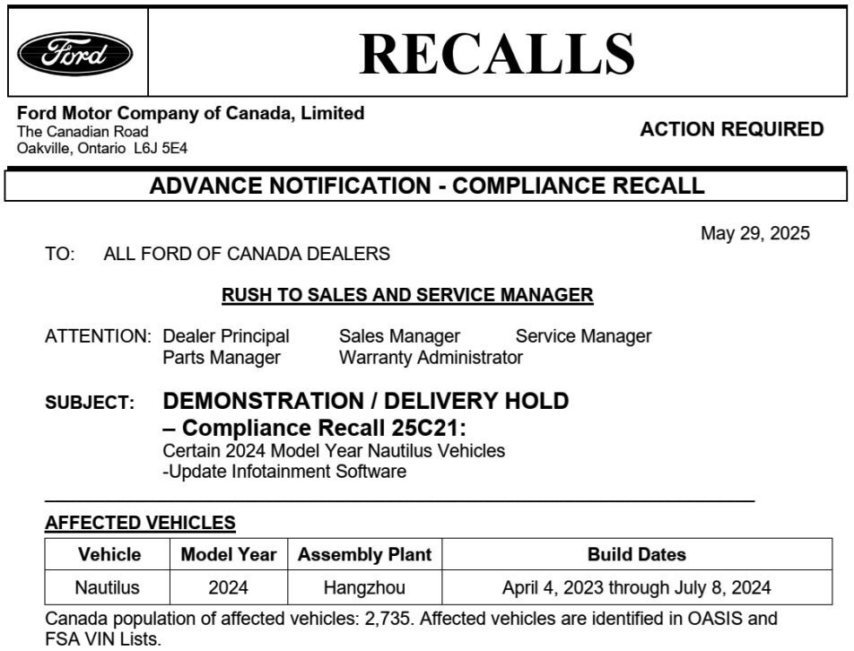
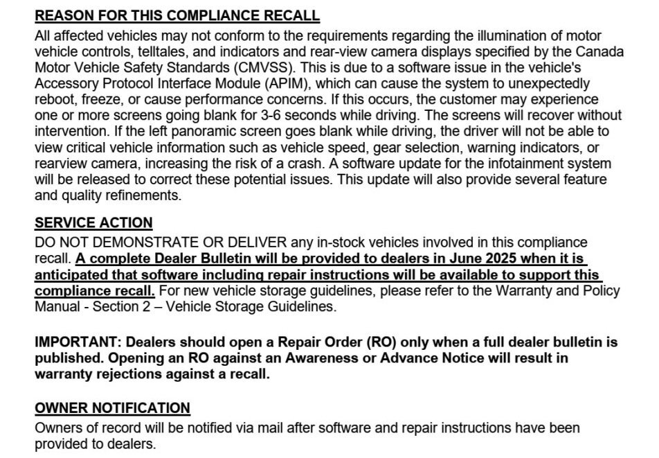
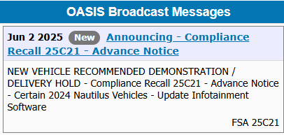
*** This is an Advance Notice -- This post will be updated when the Full Dealer Bulletin is released *** Ford of Canada is also participating in Compliance Recall 25C21... Gratitude to Forum member @markfm for the heads-up on the impending announcement of this Field Service Action (FSA).

-
@Brockdog12: Good luck!
-
*** This is an Advance Notice -- This post will be updated when the Full Dealer Bulletin is released ***
-
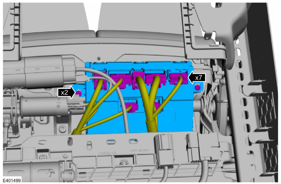
SSM 53854 - 2024-2025 Nautilus - Driver Seat Module PMI Failure After Replacement Some 2024-2025 Nautilus vehicles may exhibit a driver seat module (DSM) programmable module installation (PMI) failure with an error stating "Procedure Unsuccessful-Flash Software Failed to flash RU5T-14C030-AE" after replacement. This may be due to the incorrect DSM being installed. If the vehicle was built with RU5T-14C708-DG on or before 14-Aug-2024 the correct DSM replacement part number is RU5Z-14C708-K (engineering part number RU5T-14C708-DG), while vehicles built on or after 15-Aug-2024 the correct DSM replacement part number is RU5Z-14C708-R (engineering part number RU5T-14C708-AE). The service part catalog is currently in the process of being corrected. illustration from 2024-2025 Nautilus Workshop Manual showing DSM mounted to underside of driver seat...
-
Hmmm, maybe it's just me... Good luck!

-
Removing Side Roof Panels?
Haz replied to TonyP's topic in Glass, Lenses, Lighting, Mirrors, Sunroof (BAMR), Wipers
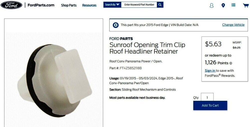
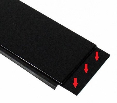
Link to scrollable-zoomable Panoramic Roof exploded diagram Link to this FordParts webpage Regarding removal of the rear side trim panel before removing the center side trim panel: In the Workshop Manual illustrations and in this FordParts photo, the center side trim panel's trailing end has a fairly long, formed flange that lays beneath the leading edge of the rear side trim panel, so removing the center side trim panel without deforming the rear side trim panel may not be possible... Link to full-view FordParts image Perhaps Forum members with first-hand knowledge of removing the panel(s) can offer their experience. Good luck!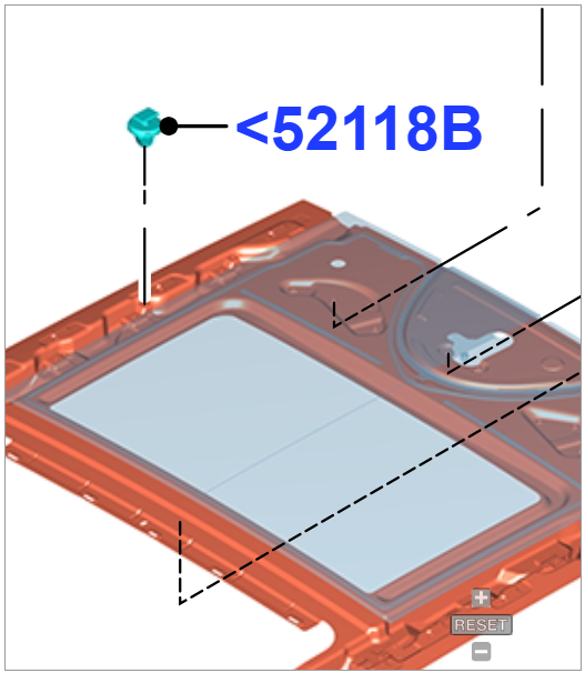
-
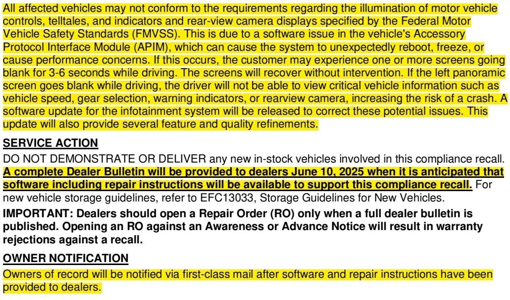
Special Service Message 53842 - 2025 Nautilus + Expedition/Navigator - Windshield RFID Transponder Not Working And Transponder Placement Some 2025 Expedition/Navigator/Nautilus customers may state that their windshield mounted toll road, home access, or other radio frequency identification (RFID) transponders are not working. 2025 Expedition, Navigator and Nautilus windshields have UV coating that may block RFID transmission. The windshield has a designated shaded area for RFID transponder placement in front of the rear-view mirror, next to the camera console, that does not contain UV coating. The online Owner Manual has been updated to include instructions for transponder placement with a picture of the shaded area, and the in-vehicle electronic Owner Manual will be updated via an over-the-air (OTA) in Q4 2025. Customers should follow transponder manufacturer provided instructions for mounting and orientation (some transponders recommend horizontal, vertical, etc.). In some cases, the transponder size may exceed the size of the windshield shaded area and a portion of the transponder may be outside of the shaded area. Many transponders will still function correctly as long as a majority of the transponder, particularly the internal RFID transmitter itself, is located in the shaded area. Customers may need to test transponder results and adjust the transponder in various positions within the shaded area until there is consistent transponder performance.
- 1 reply
-
- 3
-

-

-
2023 ST Drivers side LH window Air Vent Removal
Haz replied to Jetboy47's topic in Interior, A.C., Heat, Interior Trim
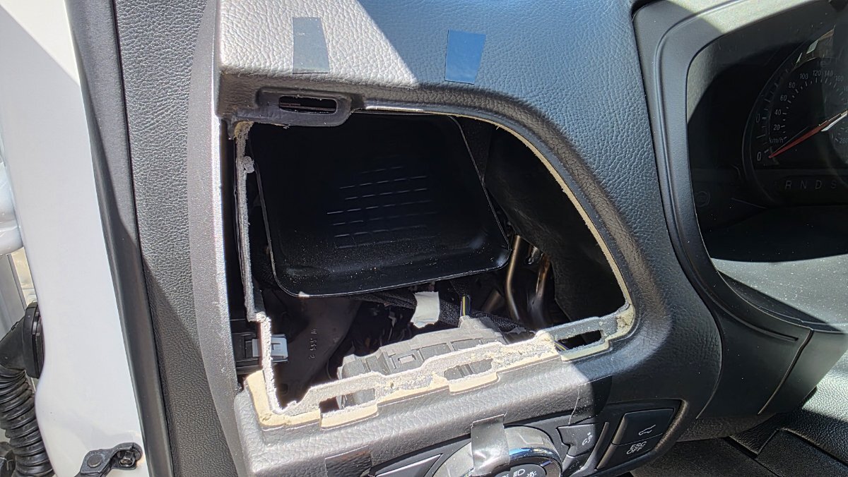
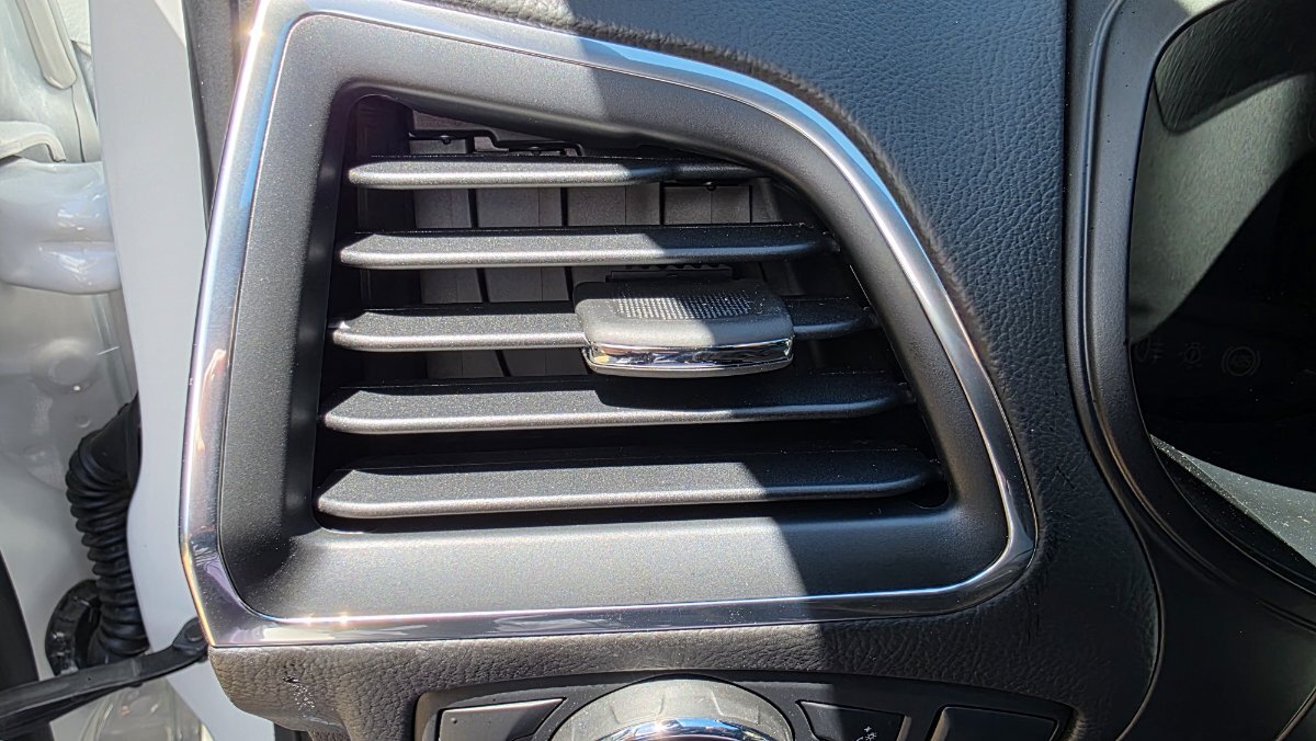
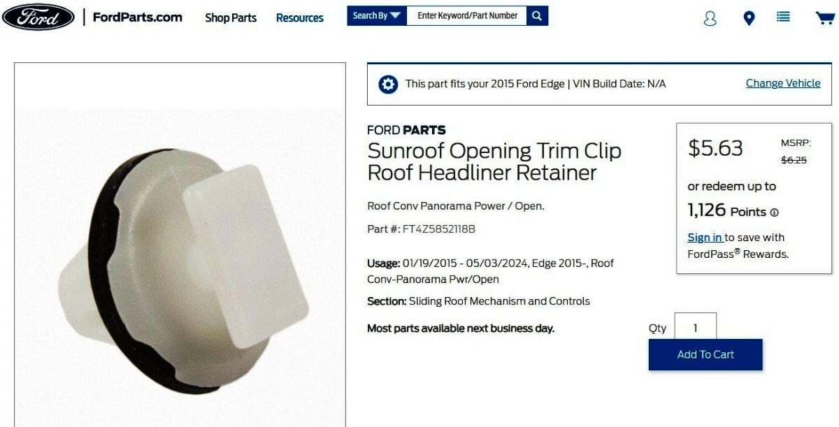
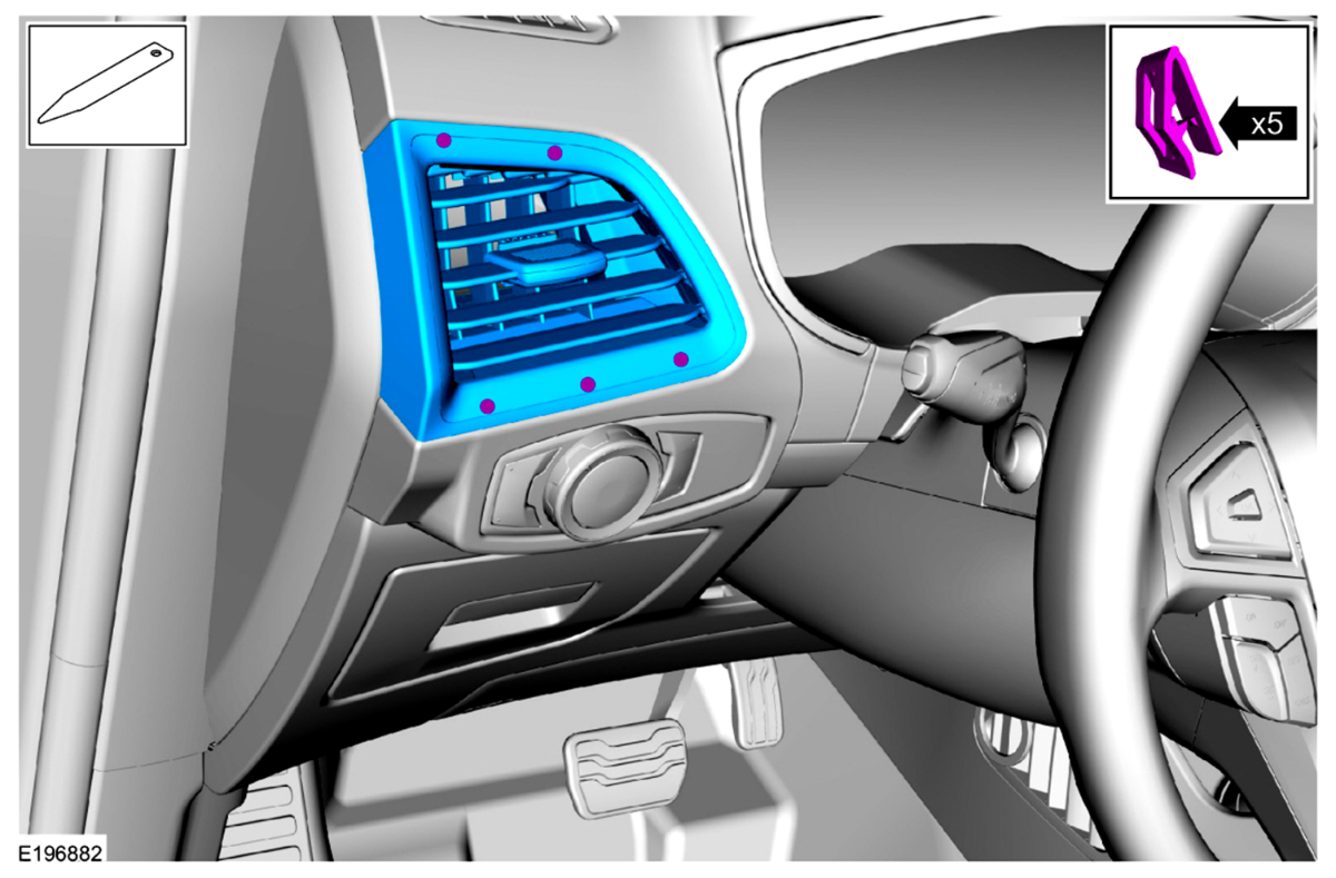
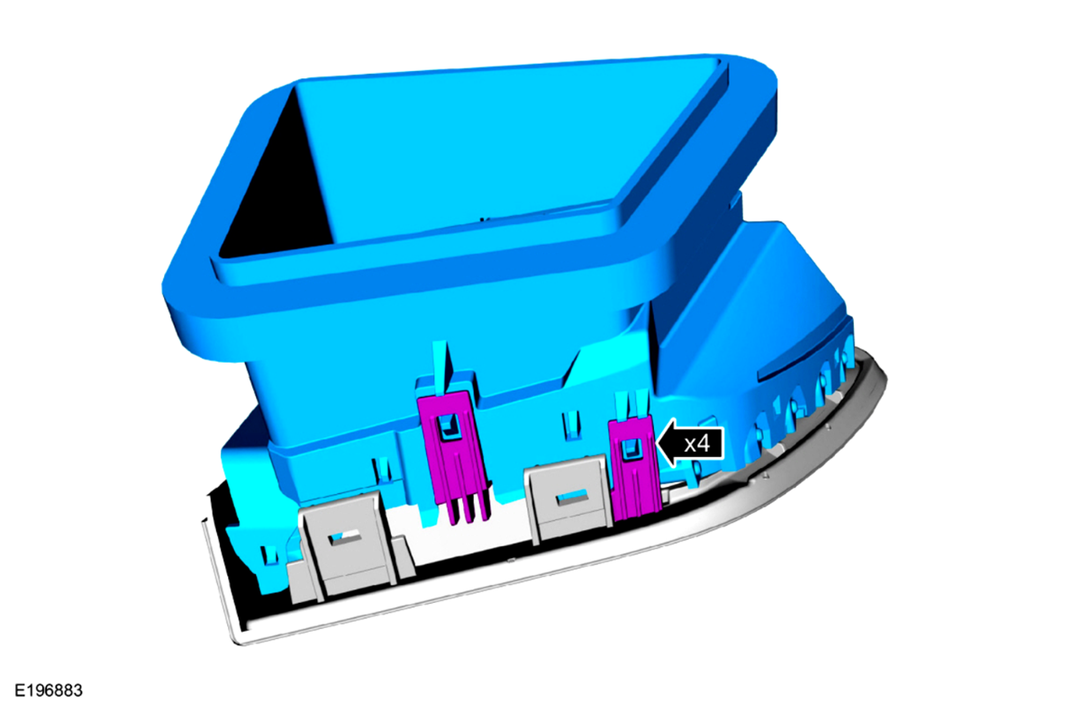
Welcome to the Forum @Jetboy47! The following is the Workshop Manual removal and installation procedure, which is also attached below as a PDF file... Driver Side Register Special Tool(s) / General Equipment Interior Trim Remover Removal Release the clips and remove the LH instrument panel finish panel. Use the General Equipment: Interior Trim Remover Release the clips and remove the driver side register assembly. Installation To install, reverse the removal procedure. Ford's online parts-selling site provides photos showing fuller detail of the retaining clips... Link to this FordParts webpage Good luck! Driver Side Register - Removal and Installation - 2022-2024 Edge Workshop Manual.pdf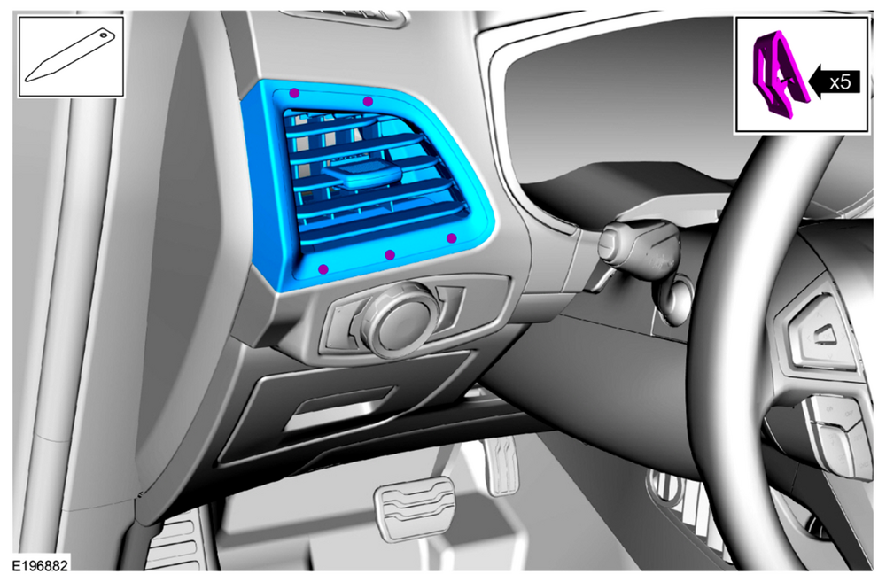

-
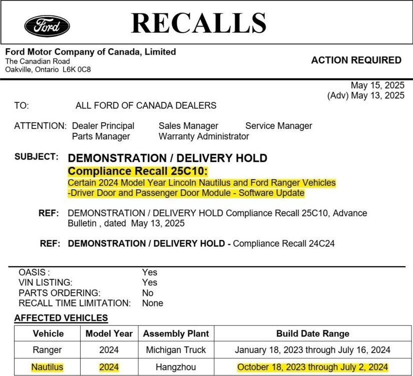
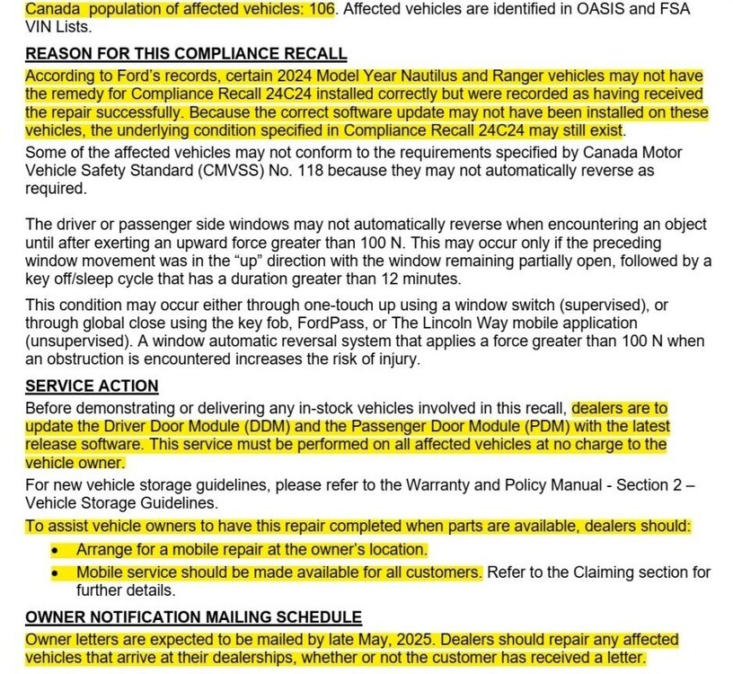
Confirming Ford of Canada's participation in Compliance Recall 25C10, per their May 15, 2025 notice to Canadian Ford dealers... Ford of Canada - Compliance Recall 25C10 - Sample ''Repair Available'' Owner Letter.pdf
- 1 reply
-
- 2
-