


Haz
-
Posts
1,568 -
Joined
-
Last visited
-
Days Won
439
Content Type
Profiles
Forums
Gallery
Everything posted by Haz
-
As you describe it, the words "official Ford" and "good deal" do not apply to your purchase. Check the eBay seller's return policy and/or your options under eBay's policies. Good luck!
- 1 reply
-
- 2
-

-
The 2019 Edge Workshop Manual provides a useful description of those newly added PTU & RDU capabilities, and how each component reacts to operational heat... Placing your device cursor over underlined acronyms may yield full-words descriptions of the acronyms. Power Transfer Unit (PTU) Operation The PTU has four (4) modes of operation: Connected, Connecting, Disconnected, and Disconnecting. Each mode is commanded by the AWD module. The power transfer unit contains a reversible DC motor and two hall effect position sensors. The motor moves the shift fork which connects or disconnects the dog clutch collar. power transfer unit position sensor A monitors the position of the actuator cam. power transfer unit position sensor B monitors the position of the shift fork. Some power transfer unit models are equipped with an oil temperature sensor. Connected Mode Connected mode is the default mode for the power transfer unit. The AWD module will command Connected mode at the beginning of each key cycle. In connected mode, the fork and dog clutch collar are positioned towards the RH side of the power transfer unit and the dog clutch is engaged. The driveshaft will then rotate at an overdrive ratio compared to the front axle shafts. Torque will be available at the RDU . Connecting Mode To connect the power transfer unit, the two halves of the Dog clutch must be within 40 RPM of each other. The AWD module calculates the speed differential based on transmission OSS , RDU Driveshaft Speed, and power transfer unit gear ratio. The actuator motor will energize and rotate the gear reduction drive and the actuator cam against the shift fork. When the dog clutch teeth line up, the cam pushes the shift fork into position and the clutch engages. It can take approximately 100 - 150ms for the dog clutch to engage after the command is sent. Disconnected Mode The AWD module will command disconnected mode based on vehicle conditions. The purpose of the disconnected mode is to reduce drag losses from spinning the driveshaft when conditions indicate AWD will probably not be needed in the near future. In disconnected mode, the fork and dog clutch collar are positioned towards the LH or transmission side of the power transfer unit. The dog clutch is disengaged. Disconnecting Mode To allow disengagement of the RDU , no torque is routed through the power transfer unit, with the dog clutch being disconnected during this mode. Depending on vehicle operating conditions, the AWD module may keep the power transfer unit engaged for the remainder of the key cycle. The AWD module will send a duty cycle command to the power transfer unit actuator motor to disengage the dog clutch. RDU Operation Power distribution clutch motor for RDU: The RDU System consists of an open type differential with an electronically controlled clutch pack that varies the torque applied to the rear axle shafts. The system has the capability to vary the amount of torque to the rear axles by controlling the clutch engagement pressure. Economy Mode: When the RDU clutch pack is not engaged, the open differential allows the rear axle system to operated as a freewheeling axle, with no torque being transmitted from the RDU to either rear axle. In this mode the vehicle will operate as a 2WD system. Connect Mode: When the AWD module determines that the AWD system function may be needed, the clutch pack is engaged to a “kiss point” by the actuator, spinning the rear axles up to speed. Once the wheel speed reaches a certain threshold, the power transfer unit will be connected (via the Torque mode), with torque provided to the RDU . Torque Mode: When the vehicle is in torque mode, the RDU clutch motor will receive angular position commands to provide a requested amount of drive torque from the drive shaft to the rear axles. The RDU controls receive a torque request in Nm, which is converted into a motor angular position request value. These incoming torque requests are updated every 10ms by the AWD module. Heat Protection - Power Transfer Unit During excessive use or when towing a trailer, the AWD system may implement a heat protection mode to protect the power transfer unit from damage. Using the input from power transfer unit temperature sensors, the AWD module performs calculations to determine the demand for use of the heat protection mode. The AWD system then reduces the commanded torque being applied by the RDU to the rear axles, and/or disconnects the power transfer unit dog clutch. Once the maximum temperature limit is reached, AWD mode only is commanded and the AWD temporarily disabled or AWD OFF message is displayed in the IPC . Heat Protection - Rear Drive Unit (RDU) During aggressive on road driving, the AWD system may implement a heat protection mode to protect the RDU clutch from damage due to overheating. On variants not fitted with power transfer unit or RDU temperature sensors, the AWD module performs calculations to determine the need for the heat protection mode. If the AWD system detects an overheat condition, it enters a locked mode. If the heat in the RDU continues to rise once in the locked mode, the AWD module disables the torque commands to RDU . This condition may be indicated by an AWD Temporarily Disabled message in the message center. To resume normal operation, stop the vehicle in a safe location and turn the engine off for at least 10 minutes. After the engine is restarted and the AWD system has adequately cooled down, the AWD Temporarily Disabled message turns off and normal AWD operation returns. In the event the engine is turned off during the stop, the AWD Temporarily Disabled message turns off when the system cools. Normal AWD operation returns once the message center displays AWD Restored. Good luck!
-
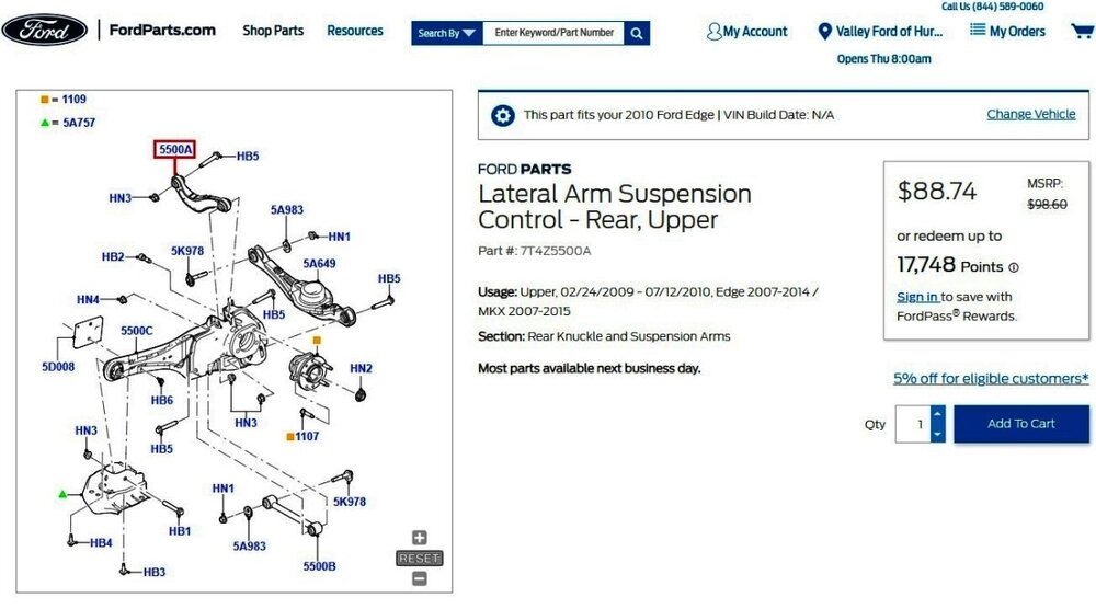
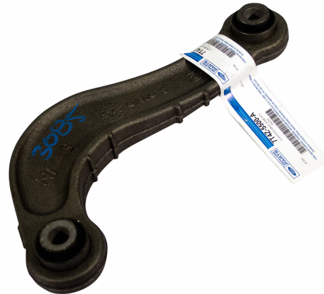
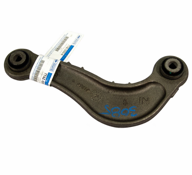
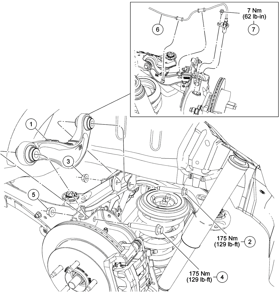
The following illustration is part of the rear Upper Arm removal and installation procedure from the 2010 Edge Workshop Manual, which is attached below as PDF document... Link to this FordParts webpage Link to this FordParts illustration, which is scrollable and zoomable in your browser Rear Upper Arm photos from FordParts,,, Good luck! Upper Arm -- Rear Suspension - Removal and Installation - 2010 Edge Workshop Manual.pdf


- 1 reply
-
- 1
-
-
Adding Adaptive suspension to my ST
Haz replied to johnmarkp's topic in Brakes, Chassis & Suspension
Additional information on Inline Connector C1026 (described as "in engine compartment on left side") attached below as PDF documents... Good luck! Inline Connector C1026 - Location - 2019 Edge.pdf Inline Connector C1026 - Pinout Diagram with Fuller Circuit Description - 2019 Edge.pdf Inline Connector C1026 - Pinout Diagram - 2019 Edge.pdf Inline Connector C1026 - Location - ENHANCED IMAGE - 2019 Edge.pdf
-
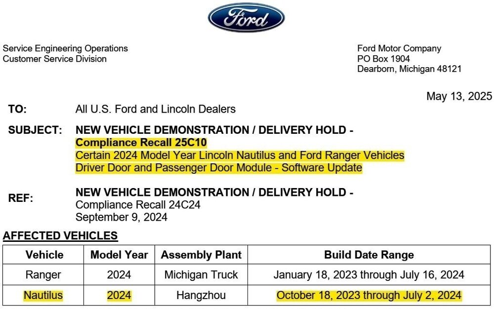
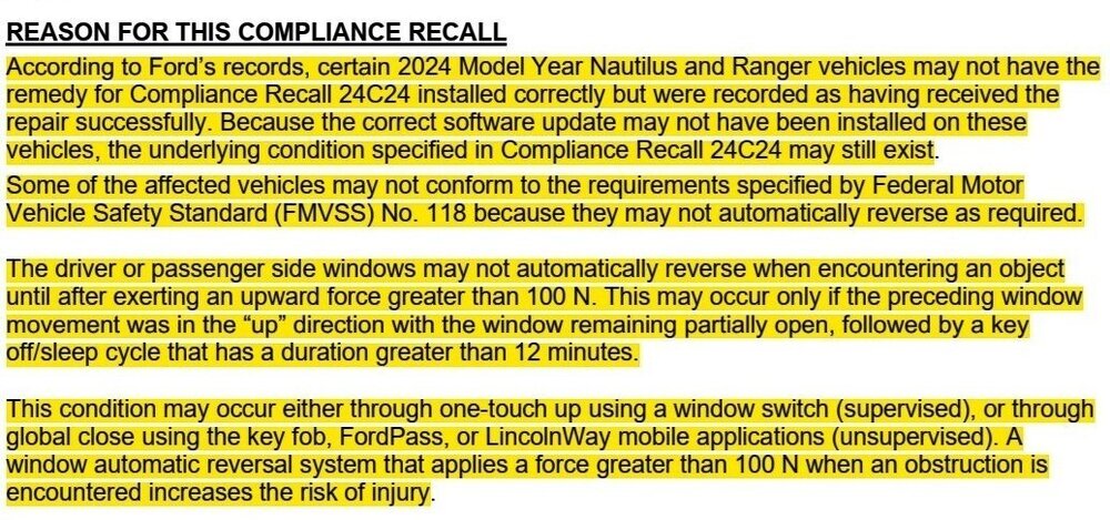
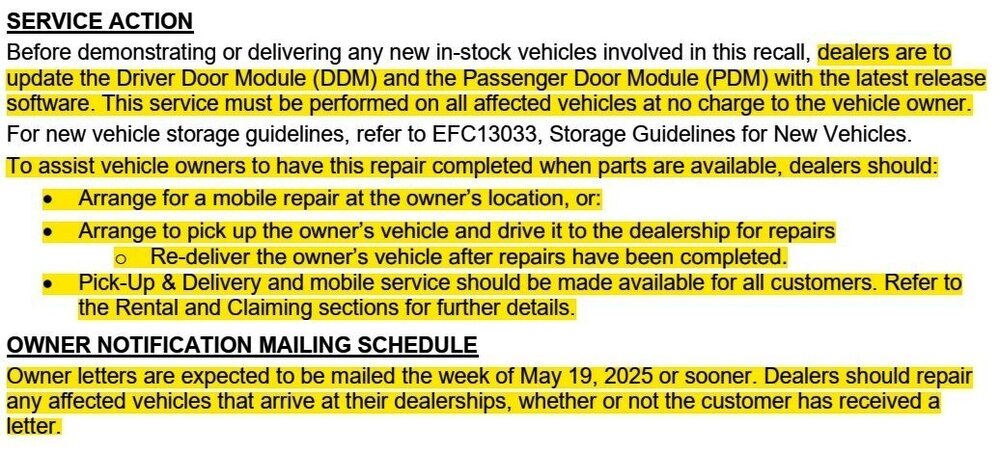
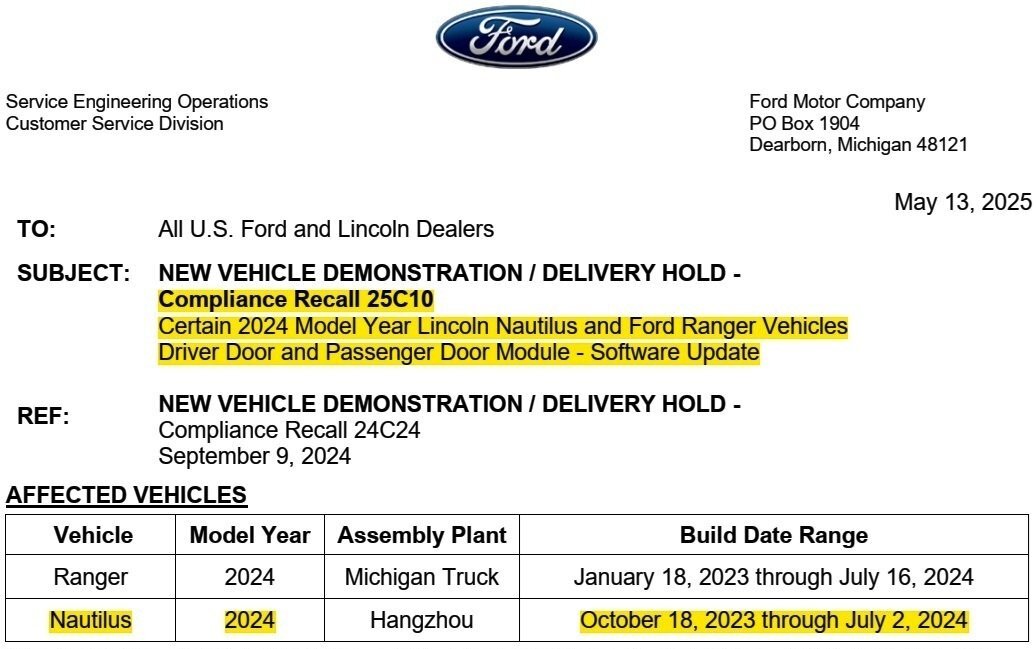
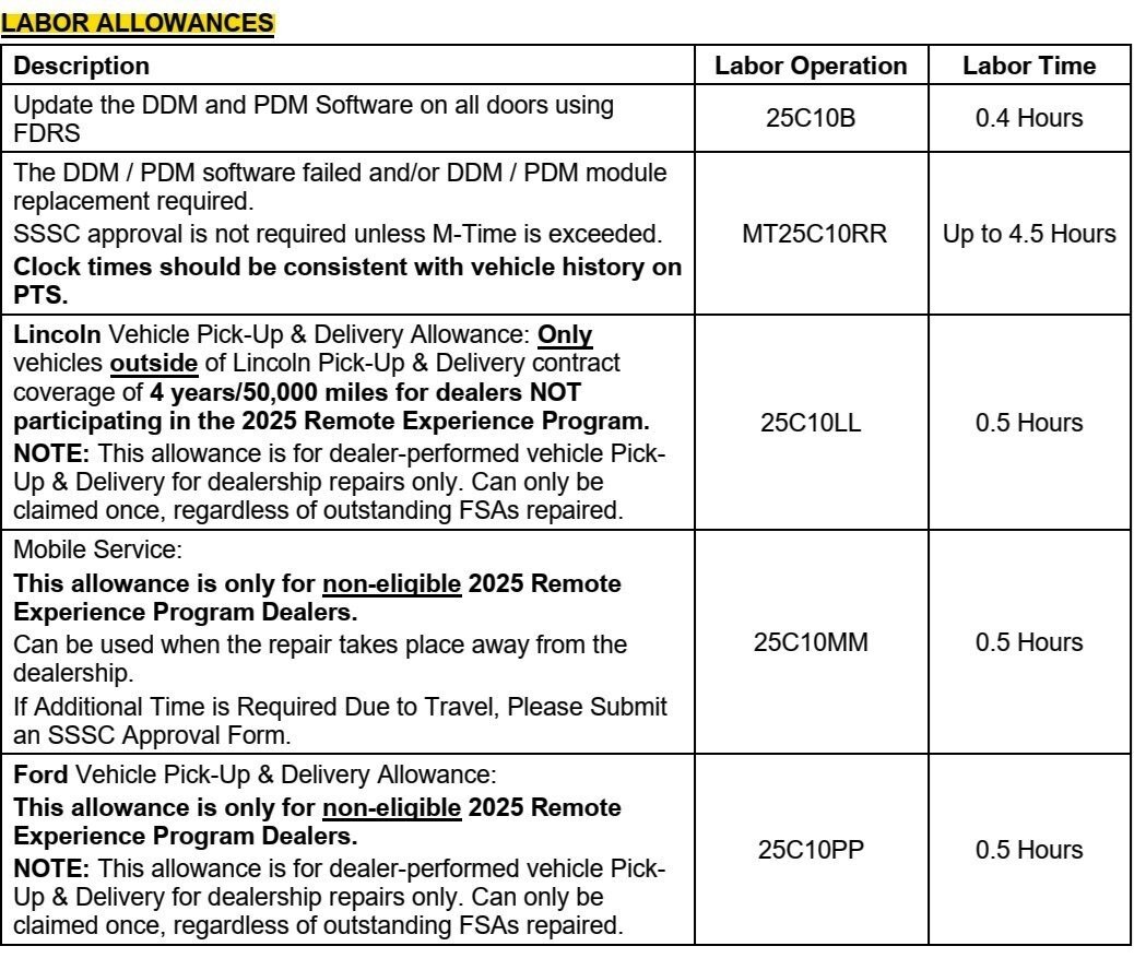
Ford has determined that some vehicles serviced under Compliance Recall 24C24 did not successfully receive software updates to their Driver Door Module (DDM) and Passenger Door Module (PDM), and, they require additional service under Compliance Recall 25C10...
-
A sample Lincoln Owner notification letter is attached below as a PDF document... Compliance Recall 25C10 - Sample Lincoln Owner Letter - 2024 Nautilus - DDM PDM Software Update.pdf

- 1 reply
-
- 2
-
-

-
Adding Adaptive suspension to my ST
Haz replied to johnmarkp's topic in Brakes, Chassis & Suspension
Additional on Headlamp Control Module (HCM)... Good luck! Headlamp Control Module (HCM) - Connector C2129 Location - 2019 Edge.pdf Headlamp Control Module (HCM) - Removal and Installation - 2019 Edge Workshop Manual.pdf Headlamp Control Module (HCM) - Module Communications Wiring Diagram - 2019 Edge.pdf -
Adding Adaptive suspension to my ST
Haz replied to johnmarkp's topic in Brakes, Chassis & Suspension
@johnmarkp: Relevant Gateway Module A (GWM) information for 2019 Edge is attached below as PDF documents... Good luck! Gateway Module - Module Communications Wiring Diagram - 2019 Edge.pdf Gateway Module - Connector C2431 Pinout Diagram - 2019 Edge.pdf Gateway Module - Connector C2431 Location - 2019 Edge.pdf Gateway Module To Remote Datalink Connector - Wiring Diagram - 2019 Edge.pdf Gateway Module A (GWM) - Removal and Installation - 2019 Edge Workshop Manual.pdf Communications Network - System Operation and Component Description - 2019 Edge Workshop Manual.pdf -
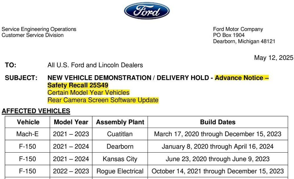
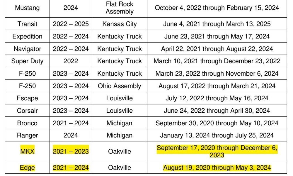
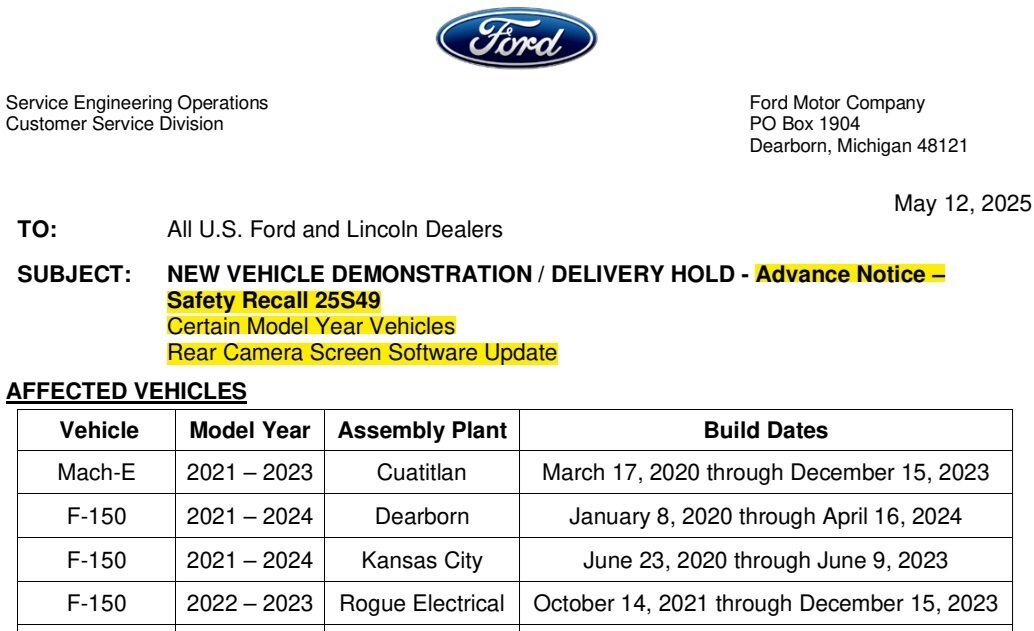
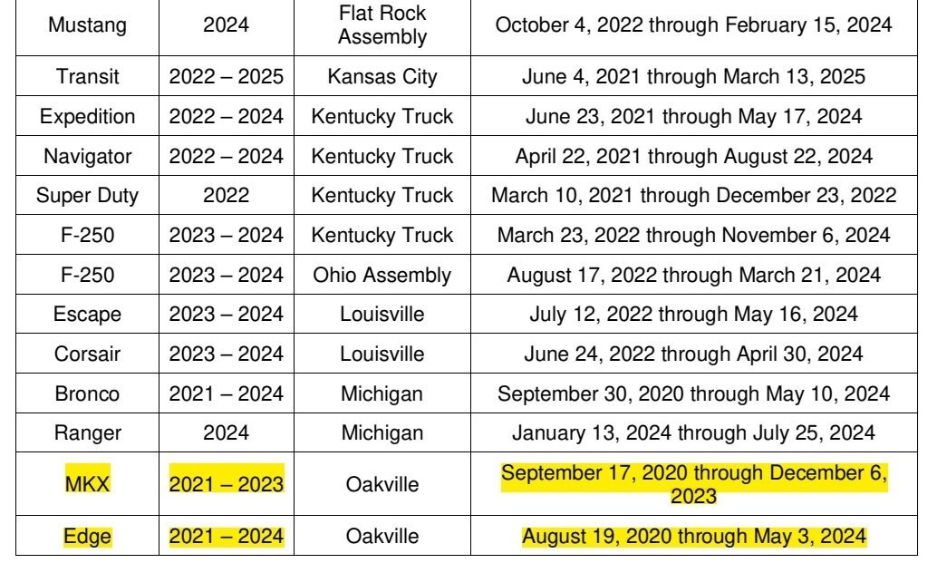
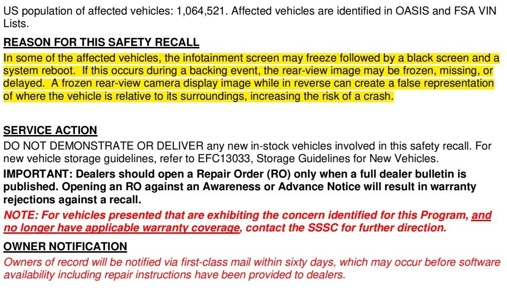
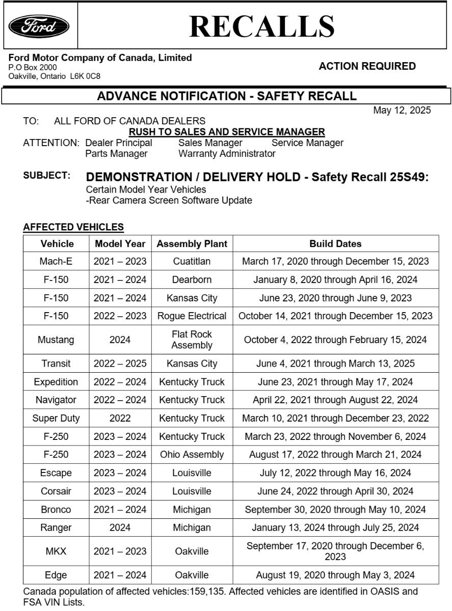
*** This is an Advance Notice -- This post will be updated when the Full Dealer Bulletin is released *** Please note: The Advance Notice letter contains a typo, indicating "MKX" for model years that clearly represent the Nautilus model...

-
SSM 53764 2020-2025 Various Vehicles - Engine Cooling System Flush Procedure Update Some 2020 Continental, 2020-2024 Edge/Nautilus, 2020-2025 Explorer/Aviator/Escape/Corsair/F-150/F-Super Duty/Ranger/Transit/E-Series, 2021-2025 Bronco, and 2022-2025 Maverick vehicles may require an engine cooling system flush to be performed for various concerns. Workshop Manual (WSM), Section 303-03 has been updated to eliminate the need to remove and install the radiator assembly to perform a radiator flush. The revised Engine Cooling System Flush procedures and supporting Engine Cooling System Specifications for 2.0L EcoBoost and 2.7L EcoBoost Edge/Nautilus are attached below as PDF documents... While the 2025 Nautilus is not included in this Special Service Message, its Flush procedure and Specifications documents are consistent with 2024 Nautilus. Engine Cooling System Flushing - 2.7L EcoBoost - General Procedures - 2020-2024 Edge, 2020-2023 Nautilus Workshop Manuals.pdf Engine Cooling System Flushing - 2.0L EcoBoost - General Procedures - 2020-2024 Edge, 2020-2025 Nautilus Workshop Manuals.pdf Engine Cooling System - 2.0L EcoBoost - Specifications - 2020-2024 Edge Workshop Manual.pdf Engine Cooling System - 2.7L EcoBoost - Specifications - 2020-2024 Edge Workshop Manual.pdf Engine Cooling System - 2.0L EcoBoost - Specifications - 2024 Nautilus Workshop Manual.pdf Engine Cooling System - 2.0L EcoBoost - Hybrid Specifications - 2024-2025 Nautilus Workshop Manual.pdf
-
Ford has re-issued its earlier SSM 53638 message as SSM 53759, presumably to keep the topic front-of-mind for Professional Technicians at dealerships and OASIS-subscribing independent repair facilities... SSM 53759 2023-2025 Various Vehicles - Trusted Real-Time Operation Network (TRON) Module Authentication DTCs After Module Replacement - Workshop Manual Update After replacement of any TRON module, the gateway module (GWM) and the TRON capable modules can set diagnostic trouble codes (DTCs) U211A, U211B, U211C, U3034, U3035, U3036, U35D9, U35DA and/or U35DB if the secret authentication security keys are not aligned between the modules, a loss of communication is occurring between modules and/or a module is not responding. This may be a result of missing the new module secret authentication security key obtained when running the Ford Diagnosis and Repair System (FDRS) "Trusted Real-Time Operation Network (TRON) Module Authentication" procedure after replacement. When replacing a TRON capable module, run the FDRS "Trusted Real-Time Operation Network (TRON) Module Authentication" procedure in the GWM tool box, not in the toolbox of the module with the DTC's, to distribute a new set of secret authentication security keys to all TRON-capable modules. Using the specific vehicle identification number (VIN), refer to Workshop Manual (WSM), Section 418-00 and 418-01 for updated DTCs, applicable TRON module listings and pinpoint tests. This creates a convenient opportunity to supplement this discussion with the previously released TRON-related Diagnostic Trouble Code (DTC) chart and Symptom chart from the 2024-2025 Nautilus Workshop Manuals... Placing your device cursor over underlined Module acronyms may yield full-words descriptions of the acronyms. Trusted Real-Time Operation Network (TRON) Diagnostic Trouble Code (DTC) Chart Diagnostics in this manual assume a certain skill level and knowledge of Ford-specific diagnostic practices. Module DTC Description Action ABS U211B:05 Control Module Message Authentication: System Programming Failure GO to Pinpoint Test F ABS U211B:08 Control Module Message Authentication: Bus Signal / Message Failure GO to Pinpoint Test J ABS U211B:43 Control Module Message Authentication: Special Memory Failure GO to Pinpoint Test B ABS U211B:51 Control Module Message Authentication: Not Programmed GO to Pinpoint Test G ABS U211B:81 Control Module Message Authentication: Invalid Serial Data Received GO to Pinpoint Test G ABS U211B:87 Control Module Message Authentication: Missing Message GO to Pinpoint Test I BCM U211B:05 Control Module Message Authentication: System Programming Failure GO to Pinpoint Test F BCM U211B:08 Control Module Message Authentication: Bus Signal / Message Failure GO to Pinpoint Test J BCM U211B:43 Control Module Message Authentication: Special Memory Failure GO to Pinpoint Test B BCM U211B:51 Control Module Message Authentication: Not Programmed GO to Pinpoint Test G BCM U211B:81 Control Module Message Authentication: Invalid Serial Data Received GO to Pinpoint Test G BCM U211B:87 Control Module Message Authentication: Missing Message GO to Pinpoint Test I DCME U211B:05 Control Module Message Authentication: System Programming Failure GO to Pinpoint Test F DCME U211B:08 Control Module Message Authentication: Bus Signal / Message Failure GO to Pinpoint Test J DCME U211B:43 Control Module Message Authentication: Special Memory Failure GO to Pinpoint Test B DCME U211B:51 Control Module Message Authentication: Not Programmed GO to Pinpoint Test G DCME U211B:81 Control Module Message Authentication: Invalid Serial Data Received GO to Pinpoint Test G DCME U211B:87 Control Module Message Authentication: Missing Message GO to Pinpoint Test I DCMF U211B:05 Control Module Message Authentication: System Programming Failure GO to Pinpoint Test F DCMF U211B:08 Control Module Message Authentication: Bus Signal / Message Failure GO to Pinpoint Test J DCMF U211B:43 Control Module Message Authentication: Special Memory Failure GO to Pinpoint Test B DCMF U211B:51 Control Module Message Authentication: Not Programmed GO to Pinpoint Test G DCMF U211B:81 Control Module Message Authentication: Invalid Serial Data Received GO to Pinpoint Test G DCMF U211B:87 Control Module Message Authentication: Missing Message GO to Pinpoint Test I DCMG U211B:05 Control Module Message Authentication: System Programming Failure GO to Pinpoint Test F DCMG U211B:08 Control Module Message Authentication: Bus Signal / Message Failure GO to Pinpoint Test J DCMG U211B:43 Control Module Message Authentication: Special Memory Failure GO to Pinpoint Test B DCMG U211B:51 Control Module Message Authentication: Not Programmed GO to Pinpoint Test G DCMG U211B:81 Control Module Message Authentication: Invalid Serial Data Received GO to Pinpoint Test G DCMG U211B:87 Control Module Message Authentication: Missing Message GO to Pinpoint Test I DCMH U211B:05 Control Module Message Authentication: System Programming Failure GO to Pinpoint Test F DCMH U211B:08 Control Module Message Authentication: Bus Signal / Message Failure GO to Pinpoint Test J DCMH U211B:43 Control Module Message Authentication: Special Memory Failure GO to Pinpoint Test B DCMH U211B:51 Control Module Message Authentication: Not Programmed GO to Pinpoint Test G DCMH U211B:81 Control Module Message Authentication: Invalid Serial Data Received GO to Pinpoint Test G DCMH U211B:87 Control Module Message Authentication: Missing Message GO to Pinpoint Test I DDM U211B:05 Control Module Message Authentication: System Programming Failure GO to Pinpoint Test F DDM U211B:08 Control Module Message Authentication: Bus Signal / Message Failure GO to Pinpoint Test J DDM U211B:43 Control Module Message Authentication: Special Memory Failure GO to Pinpoint Test B DDM U211B:51 Control Module Message Authentication: Not Programmed GO to Pinpoint Test G DDM U211B:81 Control Module Message Authentication: Invalid Serial Data Received GO to Pinpoint Test G DDM U211B:87 Control Module Message Authentication: Missing Message GO to Pinpoint Test I GWM U211A:46 Trusted Real-Time Operational Network (TRON) Configuration: Calibration/Parameter Memory Failure GO to Pinpoint Test K GWM U211B:05 Control Module Message Authentication: System Programming Failure GO to Pinpoint Test F GWM U211B:08 Control Module Message Authentication: Bus Signal / Message Failure GO to Pinpoint Test J GWM U211B:43 Control Module Message Authentication: Special Memory Failure GO to Pinpoint Test B GWM U211B:44 Control Module Message Authentication: Data Memory Failure GO to Pinpoint Test A GWM U211B:51 Control Module Message Authentication: Not Programmed GO to Pinpoint Test G GWM U211C:04 Gateway Module Message Authentication: System Internal Failure GO to Pinpoint Test H GWM U211C:05 Gateway Module Message Authentication: System Programming Failure GO to Pinpoint Test F GWM U211C:54 Gateway Module Message Authentication: Missing Calibration GO to Pinpoint Test D GWM U211C:61 Gateway Module Message Authentication: Signal Calculation Failure GO to Pinpoint Test E GWM U211C:81 Gateway Module Message Authentication: Invalid Serial Data Received GO to Pinpoint Test C GWM U211C:85 Gateway Module Message Authentication: Signal Above Allowable Range GO to Pinpoint Test N HCM U211B:05 Control Module Message Authentication: System Programming Failure GO to Pinpoint Test F HCM U211B:08 Control Module Message Authentication: Bus Signal / Message Failure GO to Pinpoint Test J HCM U211B:43 Control Module Message Authentication: Special Memory Failure GO to Pinpoint Test B HCM U211B:51 Control Module Message Authentication: Not Programmed GO to Pinpoint Test G HCM U211B:81 Control Module Message Authentication: Invalid Serial Data Received GO to Pinpoint Test G HCM U211B:87 Control Module Message Authentication: Missing Message GO to Pinpoint Test I IPMA U211B:05 Control Module Message Authentication: System Programming Failure GO to Pinpoint Test F IPMA U211B:08 Control Module Message Authentication: Bus Signal / Message Failure GO to Pinpoint Test J IPMA U211B:43 Control Module Message Authentication: Special Memory Failure GO to Pinpoint Test B IPMA U211B:51 Control Module Message Authentication: Not Programmed GO to Pinpoint Test G IPMA U211B:81 Control Module Message Authentication: Invalid Serial Data Received GO to Pinpoint Test G IPMA U211B:87 Control Module Message Authentication: Missing Message GO to Pinpoint Test I PCM U3034:00 Communication Authentication Key/Certificate Missing/Invalid: No Sub Type Information GO to Pinpoint Test G PCM U3035:00 Communication Authentication Signal Invalid Data: No Sub Type Information GO to Pinpoint Test J PCM U3036:00 Communication Authentication Signal Performance: No Sub Type Information GO to Pinpoint Test I PCM U35D9:00 Communication Authentication Attempts Exceeded Limit: No Sub Type Information GO to Pinpoint Test G PCM U35DA:00 Communication Authentication Key Programming Failure: No Sub Type Information GO to Pinpoint Test F PCM U35DB:00 Communication Authentication Key Supervision Software Failure: No Sub Type Information GO to Pinpoint Test B PDM U211B:05 Control Module Message Authentication: System Programming Failure GO to Pinpoint Test F PDM U211B:08 Control Module Message Authentication: Bus Signal / Message Failure GO to Pinpoint Test J PDM U211B:43 Control Module Message Authentication: Special Memory Failure GO to Pinpoint Test B PDM U211B:51 Control Module Message Authentication: Not Programmed GO to Pinpoint Test G PDM U211B:81 Control Module Message Authentication: Invalid Serial Data Received GO to Pinpoint Test G PDM U211B:87 Control Module Message Authentication: Missing Message GO to Pinpoint Test I PSCM U211B:05 Control Module Message Authentication: System Programming Failure GO to Pinpoint Test F PSCM U211B:08 Control Module Message Authentication: Bus Signal / Message Failure GO to Pinpoint Test J PSCM U211B:43 Control Module Message Authentication: Special Memory Failure GO to Pinpoint Test B PSCM U211B:51 Control Module Message Authentication: Not Programmed GO to Pinpoint Test G PSCM U211B:81 Control Module Message Authentication: Invalid Serial Data Received GO to Pinpoint Test G PSCM U211B:87 Control Module Message Authentication: Missing Message GO to Pinpoint Test I RFA U211B:05 Control Module Message Authentication: System Programming Failure GO to Pinpoint Test F RFA U211B:08 Control Module Message Authentication: Bus Signal / Message Failure GO to Pinpoint Test J RFA U211B:43 Control Module Message Authentication: Special Memory Failure GO to Pinpoint Test B RFA U211B:51 Control Module Message Authentication: Not Programmed GO to Pinpoint Test G RFA U211B:81 Control Module Message Authentication: Invalid Serial Data Received GO to Pinpoint Test G RFA U211B:87 Control Module Message Authentication: Missing Message GO to Pinpoint Test I SOBDMC U211B:05 Control Module Message Authentication: System Programming Failure GO to Pinpoint Test F SOBDMC U211B:08 Control Module Message Authentication: Bus Signal / Message Failure GO to Pinpoint Test J SOBDMC U211B:43 Control Module Message Authentication: Special Memory Failure GO to Pinpoint Test B SOBDMC U211B:51 Control Module Message Authentication: Not Programmed GO to Pinpoint Test G SOBDMC U211B:81 Control Module Message Authentication: Invalid Serial Data Received GO to Pinpoint Test G SOBDMC U211B:87 Control Module Message Authentication: Missing Message GO to Pinpoint Test I TCU U211A:46 Trusted Real-Time Operational Network (TRON) Configuration: Calibration/Parameter Memory Failure GO to Pinpoint Test K TCU U211B:05 Control Module Message Authentication: System Programming Failure GO to Pinpoint Test F TCU U211B:08 Control Module Message Authentication: Bus Signal / Message Failure GO to Pinpoint Test J TCU U211B:43 Control Module Message Authentication: Special Memory Failure GO to Pinpoint Test B TCU U211B:51 Control Module Message Authentication: Not Programmed GO to Pinpoint Test G TCU U211B:81 Control Module Message Authentication: Invalid Serial Data Received GO to Pinpoint Test G TCU U211B:87 Control Module Message Authentication: Missing Message GO to Pinpoint Test I Symptom Chart Diagnostics in this manual assume a certain skill level and knowledge of Ford-specific diagnostic practices. Condition Actions The TRON Diagnosis And Repair Procedure Displays The GGMT Calibration Is Not Programmed GO to Pinpoint Test L The TRON Diagnosis And Repair Procedure Displays Procedure Unsuccessful Unrecoverable Key Update GO to Pinpoint Test M The TRON Diagnosis And Repair Procedure Displays Group Key Slot Counter (GKSC) Value Over Limit For Node GO to Pinpoint Test N The TRON Diagnosis And Repair Procedure Can't Connect with Ford Backend Data Source GO to Pinpoint Test O
-
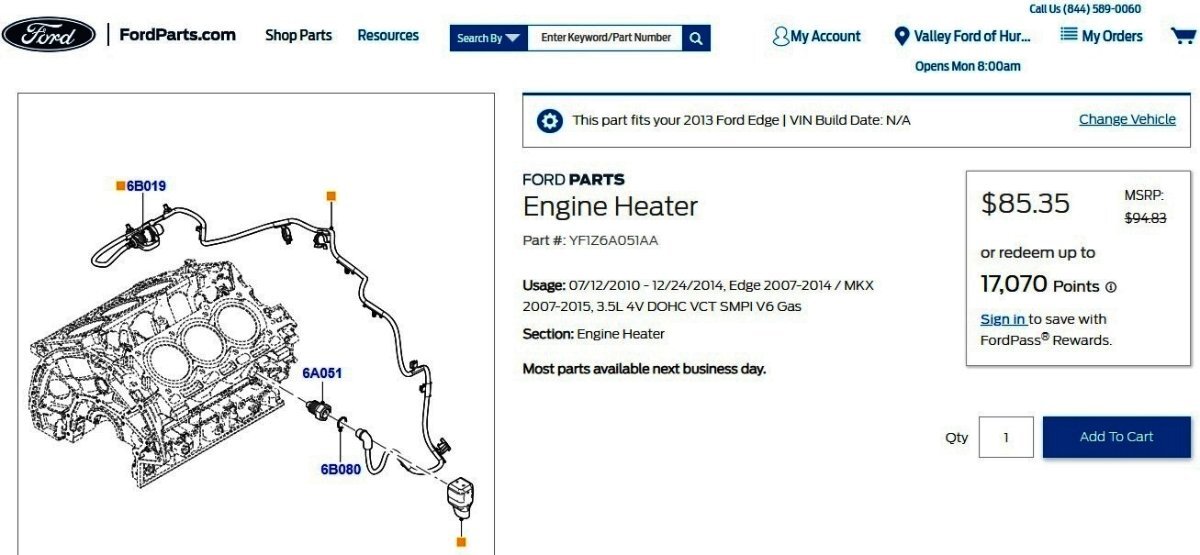
Welcome to the Forum @darkstar89! Relevant sections from the 2013 Edge Workshop Manual, which should apply to 2007-2014 Edge 3.5L 3.7L block heater installations, are attached below as PDF documents... Good luck! Link to this FordParts webpage Block Heater — 3.5L, 3.7L - Removal and Installation - 2007-2014 Edge Workshop Manual.pdf Cooling System Draining, Filling and Bleeding — 2.0L, 3.5L, 3.7L - General Procedures - 2007-2014 Edge Workshop Manual.pdf Catalytic Converter — RH - Removal and Installation - 2007-2014 Edge Workshop Manual.pdf Heated Oxygen Sensor (HO2S) and Catalyst Monitor Sensor (CMS) — Exploded View, 3.5L and 3.7L - Removal and Installation - 2007-2014 Edge Workshop Manual.pdf Exhaust Y-Pipe - Removal and Installation - 2007-2014 Edge Workshop Manual.pdf Transaxle Support Insulator — Anti-Roll - AWD Only - Removal and Installation - 2007-2014 Edge Workshop Manual.pdf


-
Hard Steering after Rack replacement
Haz replied to hirvelam's topic in Brakes, Chassis & Suspension
Additional Workshop Manual sections... Good luck! Engine Appearance Cover — Exploded View - 3.5L - Removal and Installation - 2011 Edge Workshop Manual.pdf Air Cleaner Outlet Pipe - 3.5L - Removal and Installation - 2011 Edge Workshop Manual.pdf Intake Air System Components — Exploded View - 3.5L - Removal and Installation - 2011 Edge Workshop Manual.pdf -
Hard Steering after Rack replacement
Haz replied to hirvelam's topic in Brakes, Chassis & Suspension
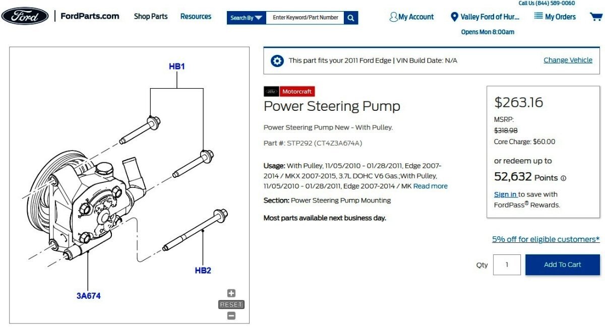
Welcome to the Forum @hirvelam! You are correct that the power steering system on your son's 2011 Edge is entirely hydraulic, and it is not an electrical Electronic Power Assist Steering (EPAS) system. Relevant sections from the 2011 Edge Workshop Manual, attached below and in an immediately following post as PDF documents, should be helpful to you. Included are procedures on power steering system filling, flushing, and purging, with the latter procedure describing the importance of removing trapped air.. NOTICE: If the air is not purged from the power steering system correctly, premature power steering pump failure may result. The condition may occur on pre-delivery vehicles with evidence of aerated fluid or on vehicles that have had steering component repairs. After you are confident trapped air has been fully purged from the system, you may use the Diagnosis and Testing document's Pinpoint Test A, which assesses the symptom(s) you describe and may help you to determine if a replacement power steering pump is recommeded... Pinpoint Test A: Steering Has Lack of Assist or Inconsistent Assist NOTE: Hard steering or lack of assist is experienced when the steering wheel effort is higher than normal. Hard steering can remain constant through the full turn, occur near the end of a turn or differ right to left. This pinpoint test is intended to diagnose the following: Power steering fluid contamination Steering gear Power steering pump Power steering hoses PINPOINT TEST A : STEERING HAS LACK OF ASSIST OR INCONSISTENT ASSIST A1 CHECK FOR POWER STEERING FLUID CONTAMINATION Check the power steering fluid for contamination. Is the power steering fluid contaminated? Yes FLUSH the power steering system. REFER to Power Steering System Flushing in this section. CHECK the system for normal operation. If assist concern still exists, GO to A2. No GO to A2. A2 CHECK THE STEERING ASSIST WITH THE ENGINE RPM RAISED NOTICE: Do not hold the steering wheel at the stops for an extended amount of time. Damage to the power steering pump may occur. Set the engine at 2,100 rpm and turn the steering wheel fully to the left and right. Is steering assist fully restored to normal with the engine rpm raised? Yes INSTALL a new power steering pump. REFER to Section 211-02. No GO to A3. A3 CHECK FOR A CHANGE OF ASSIST ON LEFT AND RIGHT TURNS With the engine at idle, turn the steering wheel fully to the left and to the right. Does the steering assist change when turning from right to left? Yes INSTALL a new steering gear. REFER to Section 211-02. No GO to A4. A4 CHECK THE STEERING LINES AND HOSES FOR RESTRICTIONS Inspect the steering lines and hoses for damage, kinks or restrictions. Are the steering lines or hoses damaged, kinked or restricted? Yes INSTALL new lines or hoses as necessary. No GO to A5. A5 MONITOR THE ENGINE RPM CHANGES NOTICE: Do not hold the steering wheel at the stops for an extended amount of time. Damage to the power steering pump may occur. NOTE: Make sure that the vehicle is on a flat dry surface, all accessories are in the OFF position and that the steering system is at normal operating temperature. Connect the scan tool. Start the engine. With the engine at idle, raise the power steering fluid temperature to 74-80°C (165-176°F) by rotating the steering wheel fully to the left and right several times. Enter the following diagnostic mode on the scan tool: DataLogger — PCM . Monitor the Engine Revolutions Per Minute (RPM) PID while turning the steering wheel quickly to the left stop position and then to the right stop position. Note the engine rpm during the turns. Does the engine rpm change (even temporarily) more than 30 rpm when turning the steering wheel? Yes INSTALL a new steering gear. REFER to Section 211-02. No INSTALL a new power steering pump. REFER to Section 211-02. If it proves necessary, the Removal and Installation procedure for the power steering pump is also attached below. Link to this FordParts webpage Specifications - Steering System - 2011 Edge Workshop Manual.pdf Specifications - Power Steering - 2011 Edge Workshop Manual.pdf Power Steering - Description and Operation - 2011 Edge Workshop Manual.pdf Steering System - Diagnosis and Testing - 2011 Edge Workshop Manual.pdf Power Steering System Flushing - Steering System General Procedures - 2011 Edge Workshop Manual.pdf Power Steering System Purging - Steering System General Procedures - 2011 Edge Workshop Manual.pdf Power Steering System Filling - Steering System General Procedures - 2011 Edge Workshop Manual.pdf Power Steering Fluid Reservoir - Removal and Installation - 2011 Edge Workshop Manual.pdf Power Steering Pump - Removal and Installation - 2011 Edge Workshop Manual.pdf Front End Body Panels — Exploded View - Removal and Installation - 2011 Edge Workshop Manual.pdf Fender Splash Shield - Removal and Installation - 2011 Edge Workshop Manual.pdf Power Steering Pump to Steering Gear Pressure Line - Removal and Installation - 2011 Edge Workshop Manual.pdf Upper Intake Manifold - 3.5L - Removal and Installation - 2011 Edge Workshop Manual.pdf
-
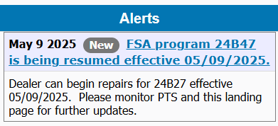
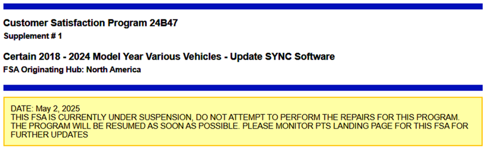
Ford has resumed Dealer repair actions under Customer Service Program 24B47...
-
TECHNICAL SERVICE BULLETIN Inaccurate Clock, Google Maps Not Displaying, And/Or Weather Not Updating Along With The Inability To Sign Into Google Automotive Services To Edit A Profile 25-2185 07 May 2025 This bulletin supersedes 24-2175. Reason for update: update the Vehicles Affected and update the Labor Operation from Actual Time to Actual Time with a cap. Model: Lincoln 2024 Nautilus Built on or before 04-Jul-2024 Markets: North American markets only Issue: Some of the vehicles listed in the Model statement above may have a clock that is inaccurate and/or weather information may not be able to update along with the inability to sign-in to Google Automotive Services to update or edit a profile. During this time the Google Maps may also not display in the panoramic display screen next to the speedometer. This may be due to a concern with the TCU module software. NOTE: It is normal for the Google Maps to not appear in the panoramic display when in calm mode or when using the Waze app. NOTE: The TCU software update that addresses the symptom listed in this article may have been delivered OTA to connected vehicles that have automatic updates enabled through the vehicle's center display screen. Enter the VIN in PTS and check the OTA Dashboard under the Connected Vehicle tab for OTA update history. If an update to the TCU has successfully completed recently and the customer is reporting the symptoms are no longer present, this article may not apply. Action: For vehicles that meet all of the criteria in the Issue and Model statements, follow the Service Procedure to reprogram the TCU. Warranty Status: Eligible under provisions of New Vehicle Limited Warranty (NVLW)/Service Part Warranty (SPW)/Service Part New Vehicle (SPNV)/Extended Service Plan (ESP) coverage. Limits/policies/prior approvals are not altered by a TSB. NVLW/SPW/SPNV/ESP coverage limits are determined by the identified causal part and verified using the OASIS part coverage tool. Labor Times Description Operation No. Time 2024 Nautilus: Perform software update for GWM, TCU and APIM per service procedure. Includes time to clear codes. 252185A 2.0 Hrs. Additional Time For Further Updates To GWM, TCU and APIM “Refer To Warranty & Policy Manual, Section 1.3 For Time Recording Requirements And Procedures For Actual Time. Ford Monitors Module Reprogramming Vehicle History Session Data To Compare Against Warranty Claiming Activity” (Can Be Claimed With Operation A) AP252185 Actual Time Up to 2.0 hours Repair/Claim Coding Causal Part: 14F546 Condition Code: 04 Service Procedure NOTE: The time required to complete this procedure varies depending on several factors including the number of module software updates required, available internet bandwidth, USB flash drive variability, and the potential that CAN flashing (software update via the DLC with FDRS) may be required. Connect to the internet with an ethernet cable, use a USB 3.2 Gen 2 or higher flash drive. When performing USB software updates, using high speed USB ports on the laptop is recommended for faster file transfer. 1. Is FSA 24B54 open on this vehicle? (1). Yes - complete and claim FSA 24B54, proceed to Step 2. (2). No - proceed to Step 2. 2. Start an FDRS session and navigate to Toolbox tab > Datalogger > body control module (BCM) and select the BATT_SOC PID. Verify the PID reads 50% or higher. NOTE: Connecting the battery charger negative clamp directly to the battery negative terminal might result in the SOC PID not immediately reflecting the improvement from charging. (1). If SOC is less than 50%, charge the battery by attaching the battery charger's negative clamp to the engine or chassis ground and not the negative battery terminal. Refer to WSM, Section 414-01. (2). If the battery is unable to achieve a 50% SOC, use the Rotunda GRX-3590 or DCA-8000 testers to verify if replacement is required. • If the battery does not need to be replaced, disconnect the Rotunda charger and perform a BMS reset using the FDRS scan tool. • If the battery is replaced, fully charge the new battery, disconnect the Rotunda charger and perform a BMS reset using the FDRS scan tool. • Claim the battery testing and replacement outside of this article. 3. Reconnect the battery charger and set it to maintain a vehicle voltage of 12.6-13.6 volts. A low battery voltage or SOC while performing a software update to any module may result in a repeat "Restart Required" message in the vehicle's center display screen or a message on the FDRS saying "Part Number Validation Failed" or "DID Validation Failed". 4. Run the "Read The Configuration Data" app in FDRS, located in Toolbox > Multi-Module tab. 5. Navigate to the SW Updates tab. Is there a software update available for any of the following modules? GWM APIM TCU (1). Yes - proceed to Step 6. (2). No - this article does not apply. 6. Prepare to update the software for the GWM, APIM, and TCU. (1). A 64GB or larger USB flash drive is required for GWM, APIM, and TCU software updates. USB 3.2 Gen 2 or higher is recommended for faster file transfer on both the computer port and the USB drive. (2). Make sure the USB flash drive being used is formatted correctly. To see the available drives, hold down the Windows icon keyboard key and press the E keyboard key. Right click on the USB flash drive and select Properties. If File System under the General tab is not exFAT, the drive must be formatted. (3). To format the USB flash drive: • Right click on the USB flash drive. • Select Format, select exFAT for the File System. • Select Default Allocation Size for the Allocation Unit Size. (4). De-selecting Quick Format is not necessary and results in a lengthier operation. 7. Using the FDRS, begin module programming by selecting the "SW Updates" tab. Follow all on-screen instructions carefully. 8. When prompted, connect the USB flash drive to the FDRS. 9. When prompted by the USB, safely remove/eject the USB flash drive from the FDRS. Start the vehicle ( KOER) then connect the USB flash drive to the USB media hub to install the software into the module. When the USB software update begins, the center display screen displays a message stating "Do Not Remove USB". The update may take 10 minutes or longer to complete. NOTE: It may take up to 5 minutes for the vehicle to recognize the USB flash drive with software update. 10. When the vehicle's center display screen prompts to restart the vehicle: (1). Turn the vehicle OFF. (2). Wait 10 minutes. (3). Restart the vehicle (KOER). The update is still in process at this time. 11. Follow FDRS on-screen prompts to complete the update. NOTE: It may take up to 5 minutes before "Update Successful" appears in the vehicle's center display screen. After 5 minutes if "Update Successful" pop-up is not shown on the center display screen, remove the USB flash drive and select YES on the FDRS prompt stating "Was The USB Update Successful" ( FDRS verifies if the module software update was successfully installed on the module). 12. Perform the software update for the GWM. Follow all update screens. If there is no GWM software update available, proceed to Step 13. (1). If there is no screen prompt indicating that the software update is in progress: • Perform the Digital Experience reset. (2). Follow the center display screen prompts. (3). Follow FDRS prompts to complete the GWM programming. • Once the pop up stating "Update Successful" appears in the center display screen, select Close, remove the USB flash drive from the USB media hub, and select Yes on USB indicating the update installed successfully. This initiates the remaining automated configuration steps and reports the module software part numbers and application software levels to the Ford online database. Failure to follow this step results in an inaccurate database as well as omitted, improperly installed, or improperly configured applications (features) such as navigation (if equipped). It is normal for the module to reset during this step. (4). Proceed to Step 13. 13. Perform the software update for the APIM. Follow all update screens. If there is no APIM software update available, proceed to Step 14. (1). If there is no screen prompt indicating that the software update is in progress: • Perform the Digital Experience reset. (2). Follow the center display screen prompts. (3). Follow FDRS prompts to complete the APIM programming. • Once the pop up stating "Update Successful" appears in the center display screen, select Close, remove the USB flash drive from the USB media hub, and select Yes on USB indicating the update installed successfully. This initiates the remaining automated configuration steps and reports the module software part numbers and application software levels to the Ford online database. Failure to follow this step results in an inaccurate database as well as omitted, improperly installed, or improperly configured applications (features) such as navigation (if equipped). It is normal for the module to reset during this step. (4). Proceed to Step 14. 14. Format the USB drive. Right click on the USB flash drive. Select Format, select exFAT for the File System. Select Default Allocation Size for the Allocation Unit Size. NOTE: The USB drive must be formatted immediately after the APIM software update (prior to updating any other module) or the subsequent updates may fail. De-selecting Quick Format is not necessary and results in a lengthier operation. 15. Perform the software update for the TCU. Follow all update screens. If there is no TCU software update available, proceed to Step 16. (1). If there is no screen prompt indicating that the software update is in progress: • Perform the Digital Experience reset. (2). Follow the center display screen prompts. (3). Follow FDRS prompts to complete the TCU programming. • Once the pop up stating "Update Successful" appears in the center display screen, select Close, remove the USB flash drive from the USB media hub, and select Yes on USB indicating the update installed successfully. This initiates the remaining automated configuration steps and reports the module software part numbers and application software levels to the Ford online database. Failure to follow this step results in an inaccurate database as well as omitted, improperly installed, or improperly configured applications (features) such as navigation (if equipped). It is normal for the module to reset during this step. (4). Proceed to Step 16. 16. Run the "Trusted Real-Time Operation Network (TRON) Module Authentication" app in FDRS, located in Toolbox > Multi-Module tab (1). From the list on the right side of the screen, download and select the Trusted Real-Time Operation Network (TRON) Module Authentication. (2). Select TRON Diagnosis and Repair from the menu items and then click Select. 17. Refresh the FDRS files. (1). Click on envelope icon. (2). Select Refresh FDRS Files (this will close FDRS when completed). (3). Launch FDRS. (4). Start new FDRS session. 18. Are there any updates available for the GWM, APIM, and/or TCU? NOTE: The option to update a module may not be available until other module(s) are updated to a certain level. The network test is a confirmation that all modules are at the latest available software. Some repairs may require multiple network tests to reveal all module dependent software. (1). Yes - proceed to Step 12. (2). No - repair is complete. © 2025 Ford Motor Company All rights reserved. NOTE: The information in Technical Service Bulletins is intended for use by trained, professional technicians with the knowledge, tools, and equipment to do the job properly and safely. It informs these technicians of conditions that may occur on some vehicles, or provides information that could assist in proper vehicle service. The procedures should not be performed by "do-it-yourselfers". Do not assume that a condition described affects your car or truck. Contact a Ford or Lincoln dealership to determine whether the Bulletin applies to your vehicle. Warranty Policy and Extended Service Plan documentation determine Warranty and/or Extended Service Plan coverage unless stated otherwise in the TSB article. The information in this Technical Service Bulletin (TSB) was current at the time of printing. Ford Motor Company reserves the right to supersede this information with updates. The most recent information is available through Ford Motor Company's on-line technical resources. TSB 25-2185 is also attached below as a PDF document... TSB 25-2185 - 2024 Nautilus - Inaccurate Clock, Google Maps Not Displaying, Weather Not Updating + Other Symptoms.pdf
-
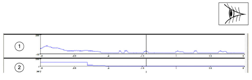
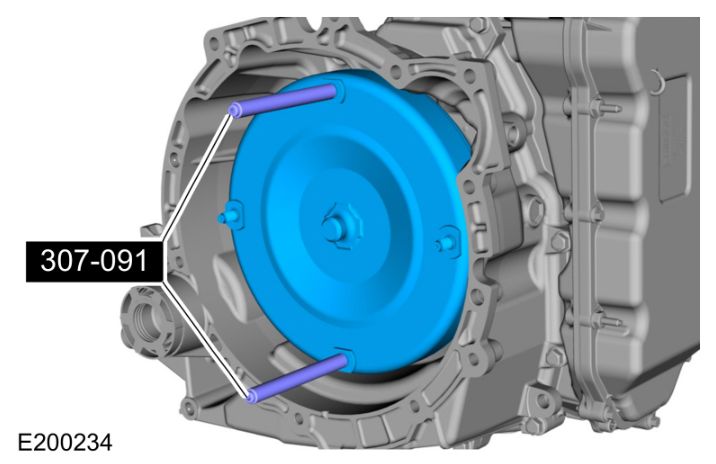
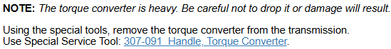
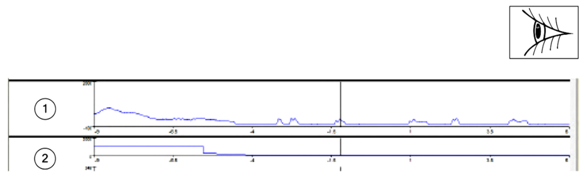
TECHNICAL SERVICE BULLETIN Torque Converter Shudder 25-2154 05 May 2025 Model: Ford 2019-2022 Edge Transmission/Transaxle: 8F35 Built On Or Before 30-Jun-2022 Lincoln 2019-2022 Nautilus Transmission/Transaxle: 8F35 Built On Or Before 30-Jun-2022 Markets: North American markets only Issue: Some of the vehicles listed in the Model statement above exhibit all of the following conditions: • Shudder condition, most noticeable at speeds below 60 mph (100 km/h) • No DTCs present • Traceable shudder event with IDS/ FDRS reading. Refer to Figure 1. Sometimes this is perceived/felt as an engine misfire. This may be due to an internal issue with the torque converter. Action: For vehicles that meet the criteria in the Issue and Model statements, follow the Service Procedure to replace the torque converter. Parts: For full parts listing, please see TSB 25-2154 attached below as a PDF document... Warranty Status: Eligible under provisions of New Vehicle Limited Warranty (NVLW)/Service Part Warranty (SPW)/Service Part New Vehicle (SPNV)/Extended Service Plan (ESP) coverage. Limits/policies/prior approvals are not altered by a TSB. NVLW/SPW/SPNV/ESP coverage limits are determined by the identified causal part and verified using the OASIS part coverage tool. Labor Times: Description Operation No. Time 2019-2022: Edge AWD: Connect Scan Tool, Road Test, Replace Torque Converter And Seal. Includes time to R&I Transmission And Reprogram The PCM (Can Be Claimed With Operations E, F, G H, J) (Do Not Use With Any Operations Outside Of This Article) 252154A 12.0 Hrs. 2019-2022: Edge FWD: Connect Scan Tool, Road Test, Replace Torque Converter And Seal. Includes time to R&I Transmission And Reprogram The PCM (Can Be Claimed With Operations E, F, G H) (Do Not Use With Any Operations Outside Of This Article) 252154B 10.1 Hrs. 2019-2022: Nautilus AWD: Connect Scan Tool, Road Test, Replace Torque Converter And Seal. Includes time to R&I Transmission And Reprogram The PCM (Can Be Claimed With Operations E, F, G H, J) (Do Not Use With Any Operations Outside Of This Article) 252154C 11.9 Hrs. 2019-2022: Nautilus FWD: Connect Scan Tool, Road Test, Replace Torque Converter And Seal. Includes time to R&I Transmission And Reprogram The PCM (Can Be Claimed With Operations E, F, G H) (Do Not Use With Any Operations Outside Of This Article) 252154D 9.9 Hrs. Additional Time To Check And Adjust Front Toe (Can Be Claimed With Operations A, B, C, D) 252154E 0.8 Hrs. Additional Time To Check And Adjust Front Toe If Equipped With Active/Adaptive Steering (Can Be Claimed With Operations A, B, C, D) 252154F 0.9 Hrs. Additional Time To Check And Adjust Front Toe If Equipped With Lane Departure (Can Be Claimed With Operations A, B, C, D) 252154G 0.9 Hrs. Additional Time To Check And Adjust Front Toe If Equipped With Active/Adaptive Steering and Lane Departure (Can Be Claimed With Operations A, B, C, D) 252154H 1.0 Hrs. Additional Time If Equipped With Power Transfer Unit Oil-to-Coolant Cooler (Can Be Claimed With Operations A And D) 252154J 0.2 Hrs. Repair/Claim Coding: Causal Part: 7902 Condition Code: 42 Service Procedure Figure 1 1. Drain The transmission fluid. Refer to WSM, Section 307-01. 2. Remove the transmission. Refer to WSM, Section 307-01. 3. Remove and discard torque converter. Refer to WSM, Section 307-01. 4. Replace the torque converter seal. Refer to WSM, Section 307-01. 5. Install the replacement torque converter. Refer to WSM, Section 307-01. 6. Reinstall the transmission. Refer to WSM Section 307-01. 7. Refill the transmission to the correct fluid level. Refer to WSM Section 307-01. 8. Reprogram the PCM using the latest software level of the appropriate scan tool. NOTE: Advise the customer this vehicle is equipped with an adaptive transmission shift strategy which allows the vehicle's computer to learn the transmission's unique parameters and improve shift quality. When the adaptive strategy is reset, the computer will begin a relearning process. This relearning process may result in firmer than normal upshifts and downshifts for several days. © 2025 Ford Motor Company All rights reserved. NOTE: The information in Technical Service Bulletins is intended for use by trained, professional technicians with the knowledge, tools, and equipment to do the job properly and safely. It informs these technicians of conditions that may occur on some vehicles, or provides information that could assist in proper vehicle service. The procedures should not be performed by "do-it-yourselfers". Do not assume that a condition described affects your car or truck. Contact a Ford or Lincoln dealership to determine whether the Bulletin applies to your vehicle. Warranty Policy and Extended Service Plan documentation determine Warranty and/or Extended Service Plan coverage unless stated otherwise in the TSB article. The information in this Technical Service Bulletin (TSB) was current at the time of printing. Ford Motor Company reserves the right to supersede this information with updates. The most recent information is available through Ford Motor Company's on-line technical resources. From the Workshop Manual... TSB 25-2154 - 2019-2022 Edge-Nautilus - 8F35 Transmission - Built on-or-before 06-30-2022.pdf
-
Ford has temporarily suspended repair actions under Customer Satisfaction Program 24B47...
-
@Todd Turner: As you say, shimming the components may not be mentioned in the Workshop Manual procedure, but it's hard to argue with success. Congratulations!
-
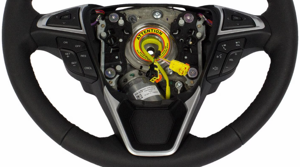
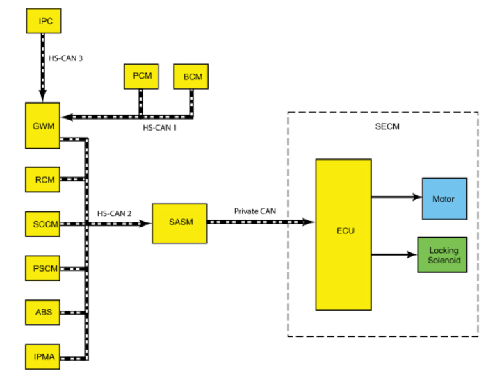
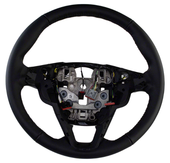
The closed-spoke steering wheels contain the motor for Adaptive Steering, as described in the 2019 Edge Workshop Manual... Adaptive Steering - Overview The adaptive steering system provides steering assist to the driver by dynamically changing the steering ratio between the steering wheel and the road wheels, thereby reducing the number of steering wheel turns required to turn the road wheels. This is accomplished through the use of a motor, worm gear and toothed hub. All adaptive steering system components are inside the steering wheel, behind the driver air bag. Additional technical detail on Adaptive Steering, from the Workshop Manual... Placing your device cursor over underlined acronyms may yield full-words descriptions of the acronyms. Adaptive Steering - System Operation and Component Description System Operation System Diagram Network Input Message Chart SECM Network Input Messages Broadcast Message Originating Module Message Purpose ABS active ABS module Used to inform the SECM an ABS event is taking place. Active front steering request ABS module Used to request steering angle changes for stability control events. EPAS fail PSCM Used to inform the SECM of an EPAS or PSCM failure. Lane keeping system status IPMA Informs the SECM of the current lane keeping system status. Odometer master value IPC This message is sent to the GWM and then to the SECM . Provides the SECM with the current odometer value in kilometers. Power pack status PCM This message is sent to the GWM and then to the SECM . Used to inform the SECM of powertrain status; OFF-torque not available, ON-torque not available, Start in Progress-torque not available, ON-torque available. Restraint impact event status RCM Informs the SECM of airbag deployment and fuel system cutoff due to a vehicle impact event. Stability control event in progress ABS module Used to inform the SECM a stability control event is taking place. Steering wheel angle ABS module Provides the SECM with steering wheel angle information for clear vision compensation. Steering wheel heat request IPC This message is sent to the GWM and then to the SECM . Informs the SECM the driver has requested the heated steering wheel to be activated. Transport mode BCM This message is sent to the GWM and then to the SECM . Used to confirm the vehicle is in normal operation mode, factory mode or transport mode. Turn signal status SCCM Informs the SECM of the current turn signal status; LEFT, RIGHT or OFF. Vehicle braking command ABS module Used to inform the SECM of vehicle braking. Vehicle configuration information BCM This message is sent to the GWM and then to the SECM . Provides the SECM with the current vehicle configuration (central car configuration). Vehicle speed PCM This message is sent to the GWM and then to the SECM . Used to inform the SECM of the current vehicle speed. Vehicle yaw data ABS module Provides the SECM with vehicle yaw data for clear vision compensation. Adaptive Steering System The SECM controls the functions of the adaptive steering system and communicates with other modules through the SASM over the HS-CAN2 . The SECM and the SASM communicate over a private CAN . To activate, the SECM requires battery voltage, ignition voltage and must communicate with other modules over the HS-CAN2 . The SECM must also receive the power pack status message from the PCM in order to activate. The SECM uses a motor to turn a toothed hub connected to the steering shaft to add or subtract incremental turns to the driver steering shaft input. At low speeds the same steering input from the driver delivers more front wheel angle, providing more low-speed agility. Low speed maneuvers require significantly less steering wheel rotation. At high speeds, straight line driving precision is increased, providing the driver with an improved highway driving experience and feel during moderate-to-high-speed cornering. As the driver turns the steering wheel, the SASM detects the speed and direction of the steering wheel rotation and transmits this information to the SECM over a private CAN . The SECM responds by activating the motor in the appropriate direction and speed to assist in turning the front wheels and reducing the necessary number of steering wheel turns required by the driver. The SECM is self-monitoring and is capable of setting and storing Diagnostic Trouble Codes (DTCs). Depending on the nature of the DTC , the SECM may engage the adaptive steering lock and may send a request to the IPC to illuminate the adaptive steering system warning indicator and display a message in the message center alerting the driver of a potential adaptive steering system concern. The warning message is sent over the HS-CAN2 to the GWM where it is converted to a HS-CAN3 message and forwarded on to the IPC over the HS-CAN3 . Adaptive Steering Lock The adaptive steering system is designed with a locking device. While the lock is engaged, the steering system is set to a fixed (1:1) steering ratio. A sound may be heard when the vehicle is started or shut off as the lock is disengaged or engaged and a slight movement of the steering wheel may be noticed while the locking action is taking place. If the vehicle loses electrical power or the SECM detects a fault while driving, the lock is engaged. Extreme operating conditions may also cause the SECM to engage the lock. This strategy prevents overheating and permanent damage to the adaptive steering system. Typical steering and driving maneuvers allow the system to cool and return to normal operation. While the lock is engaged, it is possible the steering wheel may not be straight when the vehicle is driving straight ahead and the driver may notice the steering wheel angle or "clear vision" may be off-set. The locking solenoid also engages when the ignition is set to ON and the driver door is closed, this prevents the steering wheel from turning unnecessarily while the system is off and affecting steering wheel clear vision. The locking solenoid disengages once the engine is started. Heated Steering Wheel The SECM is also the controlling ECU for the heated steering wheel system. For additional information on heated steering wheel functionality, Refer to: Steering Wheel and Column Electrical Components - System Operation and Component Description (211-05 Steering Wheel and Column Electrical Components, Description and Operation). Component Description Adaptive Steering Locking Solenoid The locking solenoid is a normally engaged (locked) solenoid which requires a voltage input to disengage (unlock). This provides a fail-safe in case of SECM or adaptive steering system failure. Adaptive Steering Motor The adaptive steering motor is a reversible, variable speed motor with an attached worm gear. The motor is internal to the steering wheel and is serviced with the steering wheel. SECM The SECM is the ECU for the adaptive steering system. The module monitors all sensor inputs and HS-CAN2 messages relating to the adaptive steering system and directly controls the output of the adaptive steering motor. The SECM is internal to the steering wheel and is serviced with the steering wheel. Conventional Edge steering wheel... Good luck!
-
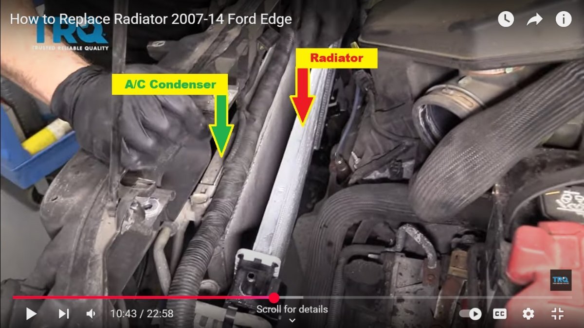
@mdjbhouse: The TRQ YouTube video you referenced above shows the Air Conditioning (A/C) Condenser remaining in place as the Radiator is being removed... You are correct that the radiator must be removed in order to access your Edge's damaged A/C Condenser and to install its replacement. Attached below, as PDF documents, are relevant Air Conditioning System sections from the 2013 Edge Workshop Manual, which detail the equipment and procedures required to successfully restore the operation of your Edge's A/C System. If you and your friend are inexperienced in A/C System repair, you may want to consider having a professional technician at a dealership or independent facility perform the repair on your behalf. Good luck! Air Conditioning — Exploded View - 2013 Edge Workshop Manual.pdf Condenser Core — 3.5L, 3.7L - Removal and Installation - 2013 Edge Workshop Manual.pdf Condenser Core — 2.0L EcoBoost - Removal and Installation - 2013 Edge Workshop Manual.pdf Air Conditioning - Description and Operation - 2013 Edge Workshop Manual.pdf Air Conditioning - Specifications - 2013 Edge Workshop Manual.pdf Air Conditioning (A-C) System Recovery, Evacuation and Charging - General Procedures - 2013 Edge Workshop Manual.pdf Refrigerant Oil Adding - General Procedures - 2013 Edge Workshop Manual.pdf Refrigerant System Tests - General Procedures - 2013 Edge Workshop Manual.pdf Air Conditioning (A-C) System Flushing - General Procedures - 2013 Edge Workshop Manual.pdf

-
Fully remove glovebox? 2019 Ford Edge ST
Haz replied to Milo M's topic in 2019-Current Edge & Nautilius
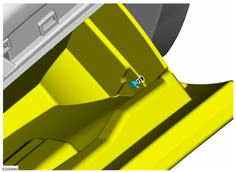
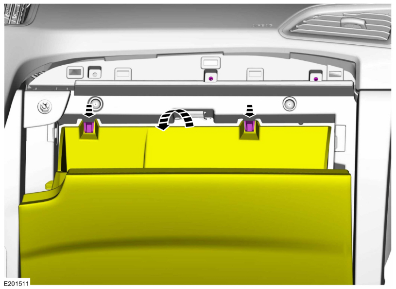
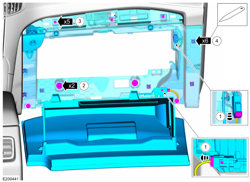
Welcome to the Forum @Milo M! To ensure your personal Health and Safety, because the Passenger Knee Bag is integral to the Glove Box assembly, please review and fulfill the Supplemental Restraint System depowering and repowering procedures... From the 2019 Edge Workshop Manual... WARNING: The following procedure prescribes critical repair steps required for correct restraint system operation during a crash. Follow all notes and steps carefully. Failure to follow step instructions may result in incorrect operation of the restraint system and increases the risk of serious personal injury or death in a crash. NOTE: Removal steps in this procedure may contain installation details. Depower the SRS . Refer to: Supplemental Restraint System (SRS) Depowering (501-20B Supplemental Restraint System, General Procedures)... (This procedure is also attached below as a PDF document) Removal Open the glove compartment. Detach the glove compartment door damper. Push the tabs and release the glove compartment door. 4 Disconnect the electrical connectors. Remove the bolts. Torque: 35 lb.in (4 Nm) Remove the screws. Torque: 22 lb.in (2.5 Nm) Release the clips and remove the glove compartment. Use the General Equipment: Interior Trim Remover (This procedure is also attached below as a PDF document) Good luck, and Work Safely! Supplemental Restraint System (SRS) Depowering - General Procedures - 2019 Edge Workshop Manual.pdf Supplemental Restraint System (SRS) Repowering - General Procedures - 2019 Edge Workshop Manual.pdf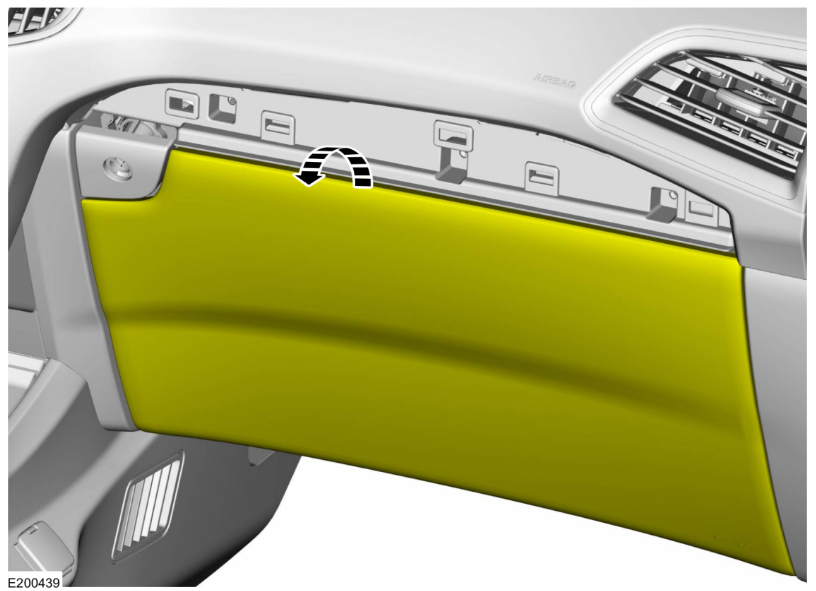
Repowering-GeneralProcedures-2019EdgeWorkshopManual.thumb.jpg.9f065584f1c6f7e91e11ee548f927a78.jpg)
Depowering-GeneralProcedures-2019EdgeWorkshopManual.thumb.jpg.d3c4a5d95affb20f562f0beac109900e.jpg)
- 1 reply
-
- 3
-
-
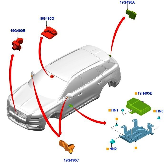
@Wubster100: Perhaps I missed it, but have you considered 2021-2023 Nautilus side mirrors/cameras? EDIT: Okay, Senior Moment [January seems so long ago], 2020 Nautilus info is on page 1 of this discussion, but might 2021-2023 Nautilus be helpful? Below and attached as PDF documents... Link to this FordParts webpage Good luck! Side Parking Aid Camera - Removal and Installation - 2021-2023 Nautilus Workshop Manual.pdf Exterior Mirror - Removal and Installation - 2021-2023 Nautilus Workshop Manual.pdf Parking Aid - Component Location - 2021-2023 Nautilus Workshop Manual.pdf Parking Aid - Overview - 2021-2023 Nautilus Workshop Manual.pdf Parking Aid - System Operation and Component Description - 2021-2023 Nautilus Workshop Manual.pdf 360 Camera Parking Aid - Wiring Diagram #1 - 2021-2023 Nautilus.pdf 360 Camera Parking Aid - Wiring Diagram #2 - 2021-2023 Nautilus.pdf 360 Camera Parking Aid - Wiring Diagram #3 - 2021-2023 Nautilus.pdf 360 Camera Parking Aid - Wiring Diagram #4 - 2021-2023 Nautilus.pdf 360 Degree View Camera Alignment - General Procedures - 2021-2023 Nautilus Workshop Manual.pdf 360 Degree View Camera Alignment - Specifications - 2021-2023 Nautilus Workshop Manual.pdf
-
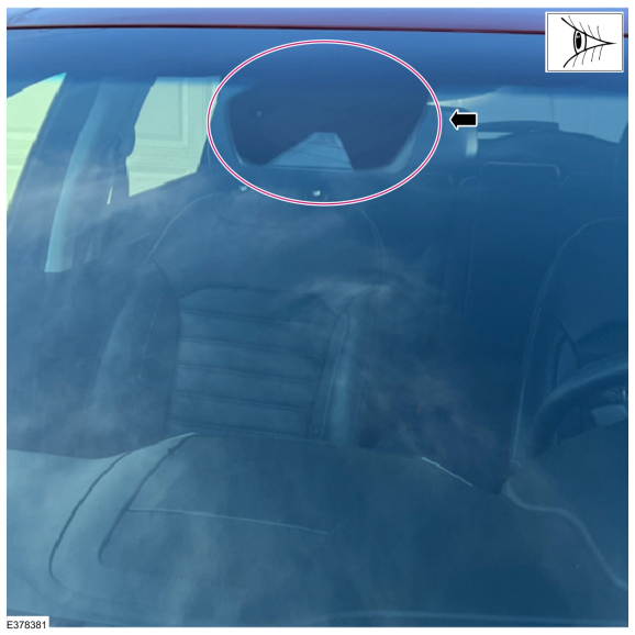
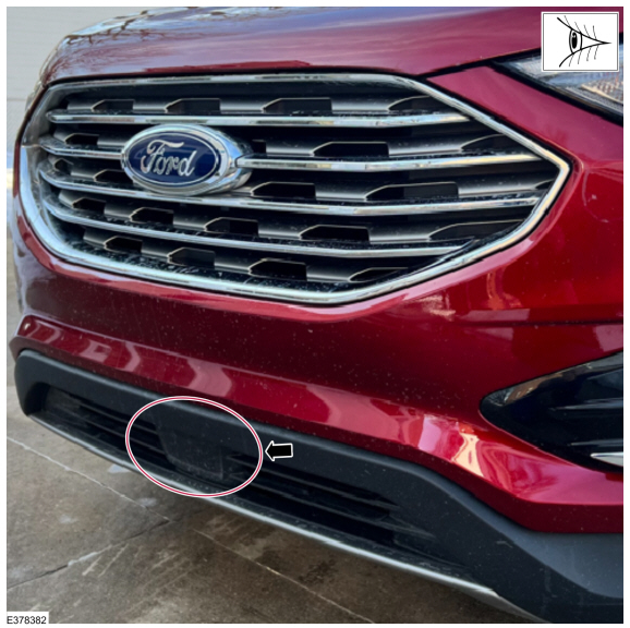
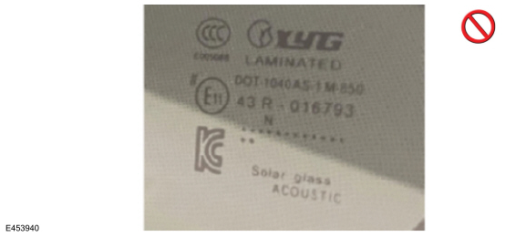
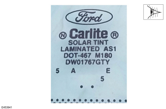
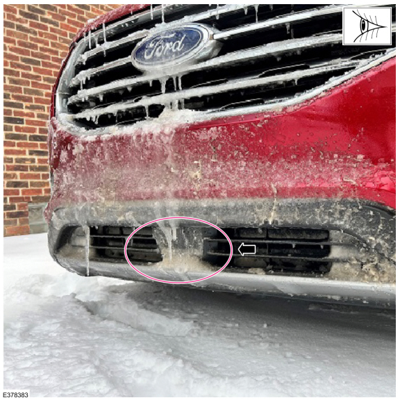
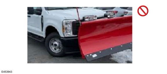
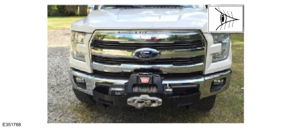
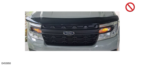
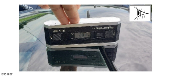
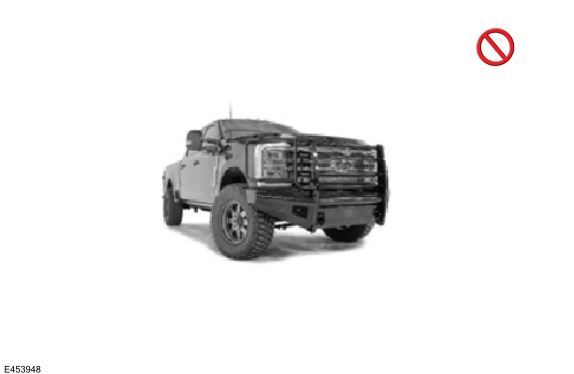
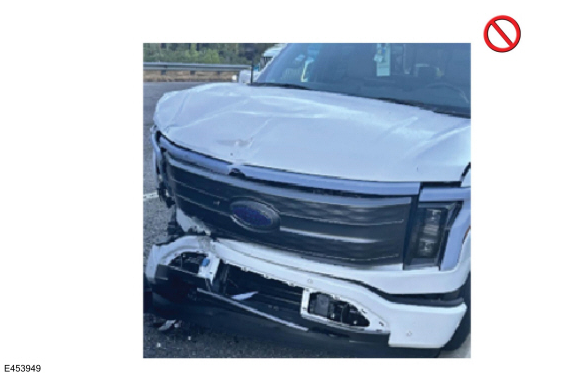
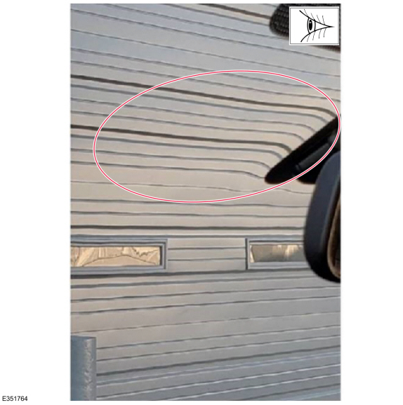
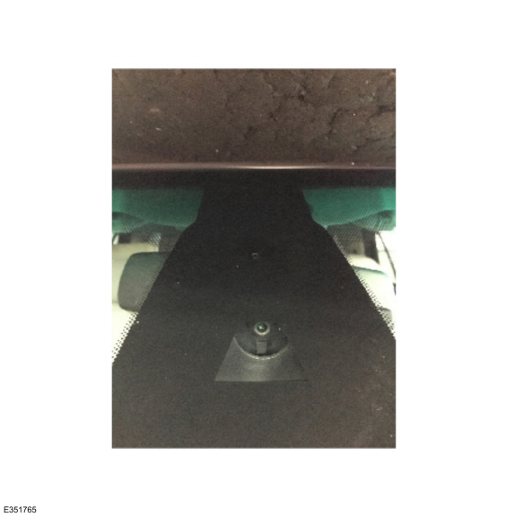
GENERAL SERVICE BULLETIN Adaptive Cruise, Pre-Collision And Collision Avoidance System Functionality Diagnostics 25-7042 25 April 2025 This bulletin supersedes 23-7031. Reason for update: Service Procedure and vehicle model years affected Markets: North American markets only Summary This article is intended to aid in the warrantability for vehicles with difficulty resolving IPMA or CCM alignment and/or functionality concerns. Service Information Adaptive cruise control and pre-collision assist systems can use a forward windshield camera only IPMA or a combination of IPMA and a CCM. Make sure which system is present on the vehicle so the system evaluation is completed properly. The forward collision system warning indicator will be illuminated when the vehicle is in transport mode. Prior to any diagnosis, make sure the vehicle is not in transport mode. For further information on transport mode, refer to WSM, Section 419-10. Using the FDRS tool, check the PID for "ALGN_OFF -CCM". A value greater than +/-3 degrees indicates a mounting issue with the CCM, not necessarily a defective module. Check for CCM or mounting surface damage and aftermarket components (shown below). CCM Alignment Incorrect: If issue remains after addressing outside factors, perform the CCM alignment procedure. Refer WSM, Section 419-03, Cruise Control Radar Alignment. Notes regarding radar drive alignment: 1. The radar needs to see 150-200 stationary targets on either side of the road to identify the center of the lane. An incorrect speedometer reading will inhibit the radar from detecting stationary targets. 2. These targets increment as the vehicle is driving over 20 mph (33 km/h). 3. The faster it sees these targets the faster it will complete the process. 4. Loss of communication and internal fault DTCs will prevent completion of the process. 5. Key cycles between initiation of the drive alignment and the drive will move the vehicle out of alignment mode. Locations of IPMA/sensor and CCM sensor IPMA (near rear view mirror) forward windshield camera (Figure 1) Figure 1 CCM (in the front grille, either visible or behind bumper) RADAR sensor (Figure 2) Figure 2 Examples Of Non-Warrantable And Warrantable Conditions IPMA/ CCM functions can be affected by several factors that are not indicative of defect. Typical non-warrantable causes of IPMA/ CCM conditions IPMA: • Aftermarket Windshield • Environmental factors such as sun position, glare, moisture, frost, snow, ice, and dust/dirt • Aftermarket tinting or windshield banners/stickers • Aftermarket accessories such as but not limited to snowplow, winch, bug guard, etc. • Windshield not installed correctly. Refer to date coding to determine factory or aftermarket installation CCM: • Vehicle squatting from cargo weight • Modifications that affect vehicle ride height, stance, or speedometer such as but not limited to lift kit, lowering kit, leveling kit and/or incorrect tire size • CCM mounting hardware bent or damaged or improper CCM mounting • Incorrect front license plate/bracket mounting • Aftermarket or incorrect bumper or grille • Brush guard installed • Snowplow or snowplow mounting hardware installed • Other aftermarket accessories installed on front of vehicle • Facia damaged, facia installed incorrectly, or aftermarket facia installed Typical warrantable conditions • Glass distortion can distort the camera’s view and prevent camera alignment and functionality. Refer to glass logo to determine factory glass. • IPMA mounting and/or bracket off-center, not clocked properly or not secured to windshield Aftermarket Windshield Installation. Refer To Glass Logos, One Aftermarket Example (Figure 3), One Factory Example (Figure 4) (Non-Warrantable) Figure 3 - Example of aftermarket windshield Figure 4 - Example of factory windshield Environmental Factors Such As Sun Position, Glare, Moisture, Frost, Snow, Ice, And Dust/Dirt (Non-Warrantable) (Figure 5) Figure 5 Aftermarket Tinting Or Windshield Banners/Stickers (Non-Warrantable) (Figure 6) Figure 6 Aftermarket Accessories Such As But Not Limited To Snowplow, Winch, Bug Guard (Non-Factory), Etc. (Non-Warrantable) (Figures 7-9) Figure 7 Figure 8 Figure 9 Windshield Not Installed Correctly. Refer To Glass Logo To Determine Factory Or Aftermarket Installation (Non-Warrantable) (Figure 10) Figure 10 Vehicle Squatting From Cargo Weight (Non-Warrantable) (Figure 11) Figure 11 Modifications That Effect Vehicle Ride Height, Stance, Or Speedometer Such As But Not Limited To Lift Kit, Lowering Kit, Leveling Kit And/Or Incorrect Tire Size (Non-Warrantable) (Figures 12-13) Figure 12 Figure 13 CCM Mounting Hardware Bent Or Damaged Or Improper CCM Mounting (Non-Warrantable) (Figure 14) Figure 14 Aftermarket Or Incorrect Bumper Or Grille (Non-Warrantable) (Figure 15) Figure 15 Brush Guard Installed (Non-Warrantable) (Figure 16) Figure 16 Facia Damaged, Facia Installed Incorrectly, Or Aftermarket Facia Installed (Non-Warrantable) (Figure 17) Figure 17 Glass Distortion Can Distort The Camera’s View And Prevent Camera Alignment And Functionality. Refer To The Glass Logo To Determine Factory Glass. (Warrantable) (Figure 18) Figure 18 IPMA Mounting And/Or Bracket Off-Center, Not Clocked Properly Or Not Secured To Windshield (Warrantable) (Figure 19) Figure 19 © 2025 Ford Motor Company All rights reserved. NOTE: This information is not intended to replace or supersede any warranty, parts and service policy, workshop manual (WSM) procedures or technical training or wiring diagram information.


- 1 reply
-
- 2
-
-


Repowering-GeneralProcedures-2019EdgeWorkshopManual.jpg.9f10907fda73551e97ea8dc5d2b7bc33.jpg)
Depowering-GeneralProcedures-2019EdgeWorkshopManual.jpg.04864bd831dad91e97de94d0c707fd8a.jpg)
