Haz
-
Posts
1,568 -
Joined
-
Last visited
-
Days Won
439
Content Type
Profiles
Forums
Gallery
Everything posted by Haz
-
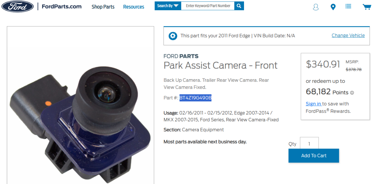
Ford's online parts-selling site offers no relief on pricing, but does reveal the Service part's prefix and suffix have changed to BT4Z19G490B, which yields a comparably broad range of web-searched sources & pricing... Link to this FordParts webpage Good luck!

-
Adding Adaptive suspension to my ST
Haz replied to johnmarkp's topic in Brakes, Chassis & Suspension
Attached... Good luck! Vehicle Dynamic Suspension - System Operation and Component Description - 2019 Fusion Workshop Manual.pdf Vehicle Dynamic Suspension - Wiring Diagram Page 1 - 2019 Fusion.pdf Vehicle Dynamic Suspension - Wiring Diagram Page 2 - 2019 Fusion.pdf Vehicle Dynamic Suspension - Wiring Diagram Page 3 - 2019 Fusion.pdf -
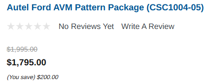
As you likely already know, BIG... ... and CO$TLY... Ford Official Aftermarket Digital image for printing by local digital sign printer It wouldn't hurt to ask a Ford/Lincoln dealer if they'd attempt the 360-degree camera alignment procedure -- or a larger independent shop or collision repair center. Good luck!

-
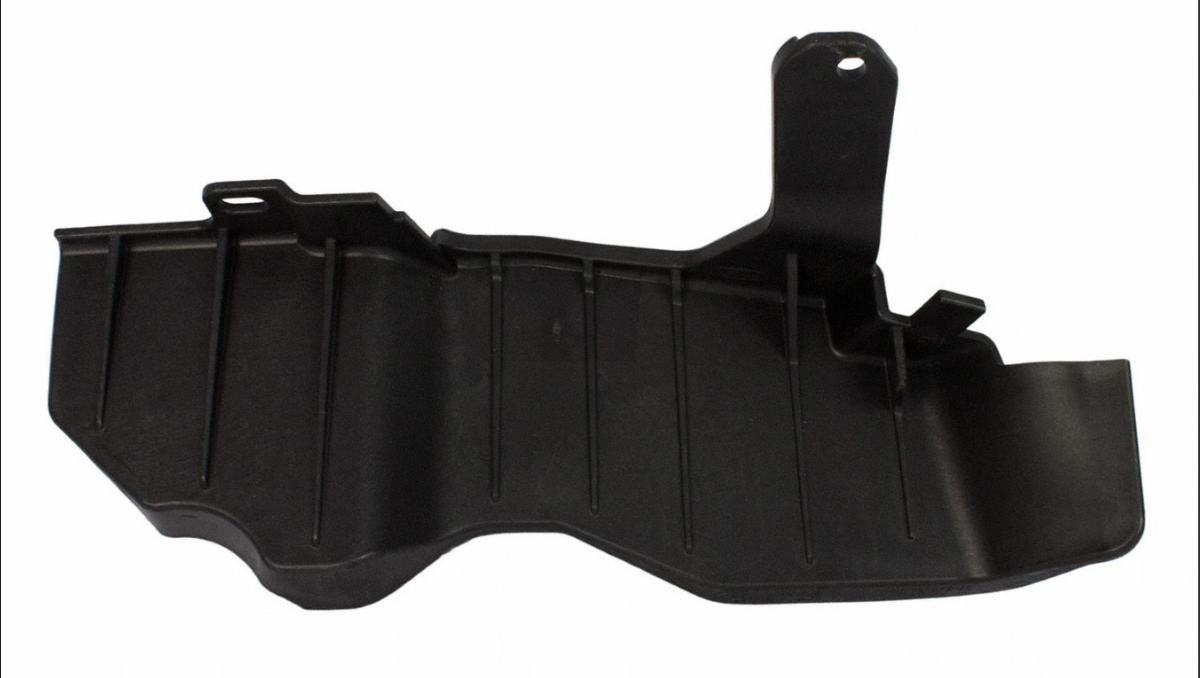
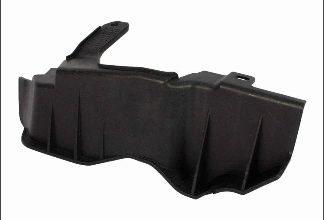
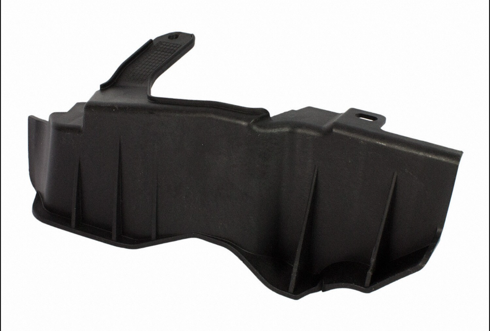
@fishx65: From Forum member @Kclonn's first post in the above-linked Factory Trailer Hitch discussion... "I just bought a new 2022 Edge Titanium and it came with the trailer hitch option. I noticed that the bottom (gray) part of the rear bumper was not attached to anything and flapped at hiway speeds." For additional info, see the discussion: Factory Trailer Hitch. Good luck!
-
Tire inner shoulder wear and no chamber adjustment
Haz replied to Gibbs Garage's topic in Brakes, Chassis & Suspension
Additional documents... Good luck! Ride Height Measurement - General Procedures - 2017 Edge Workshop Manual.pdf Wheels and Tires - Diagnosis and Testing - 2017 Edge Workshop Manual.pdf PINPOINT TEST A - INNER EDGE, SHOULDER WEAR - Diagnosis and Testing - 2017 Edge Workshop Manual.pdf -
Excellent addition, @Wubster100! Good luck!

-
I suspect you are describing the rear Air Deflector that is thoroughly covered in this discussion started by Forum member @Kclonn in June 2022... The part was discontinued and, more recently, in scarce supply -- though Forum member @rafeeki indicated as having a spare on hand in December 2024. Good luck!
-
Tire inner shoulder wear and no chamber adjustment
Haz replied to Gibbs Garage's topic in Brakes, Chassis & Suspension
Somewhat ironically, the Suspension System Specifications page is identical in both the 2017 Edge and 2016 Edge Workshop Manuals, with each bearing the 2016 model year Edge reference in its upper right corner, as shown on the below-attached PDF page... Good luck! 2016 Edge + 2017 Edge Workshop Manuals - Suspension System Specifications.pdf -
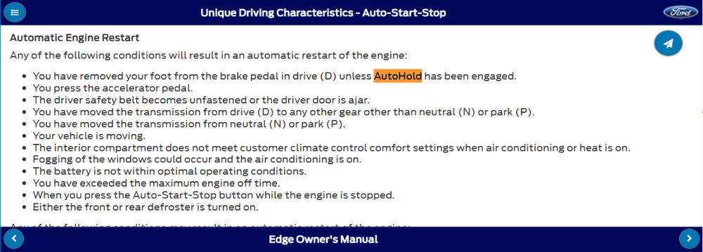
2024 Edge Workshop Manual - China region... Placing your device cursor over underlined acronyms may yield popup full-words meanings for acronyms. Auto Hold The auto hold feature is activated and deactivated through the use of the auto hold switch located on the FCIM . For the system to activate, the vehicle must not be moving, the driver safety belt must be buckled and the driver door must be closed. The ABS module receives the driver safety belt buckle status from the RCM and driver door status from the BCM , while brake system pressure and the wheel speed are received from ABS sensors. This information allows the ABS module to determine if the vehicle is stopped. Once the previous conditions have been met the auto hold feature can be activated. When the switch is pressed, the FCIM receives a ground signal from the auto hold switch and sends an auto hold message to the GWM over the HS-CAN3 . The GWM relays the message to the ABS module over the FD-CAN . The ABS module then sends a message to the instrument cluster through the GWM indicating the auto hold feature has been activated and the instrument cluster illuminates the auto hold indicator. The auto hold indicator illuminates when the IPC receives a message from the ABS module through the GWM . Once the auto hold feature is activated and the driver presses the brake pedal, the ABS module closes the isolation valves in the HCU to maintain the current brake system pressure at the wheel ends. The ABS module maintains the pressure until the driver presses the accelerator pedal, shifts the transmission into PARK or after a specific time limit has been reached. The ABS module engages the parking brake after 2-10 minutes, depending on the grade of incline the vehicle is currently stopped on, the steeper the grade, the shorter the time. Auto Hold Switch The auto hold switch is a momentary contact, push button switch and is part of the FCIM . Normal Operation and Fault Conditions Vehicles equipped with EPB are also equipped with an auto hold feature. This feature must be enabled by the driver by pressing the auto hold switch once the driver seatbelt is buckled and the driver door is closed. Pressing the auto hold switch in the FCIM enables the auto hold feature, but does not activate auto hold. When the switch is pressed, the FCIM sends a message to the ABS module indicating the system has been enabled. The ABS module then waits for messages from the RCM and BCM as well as ABS sensor information to indicate the auto hold feature can be activated. Once all criteria has been met, the ABS module activates the auto hold feature. In the case of a system error, the instrument cluster displays messages and icons. China region Search-function is not locating Auto Hold switch and other FCIM controls in Wiring Diagrams or Workshop Manual procedures, and no China-region Owner's Manual is shown. Hopefully, the above verbiage provides you sufficient Auto Hold awareness at this stage of your inquiry. Good luck!
-
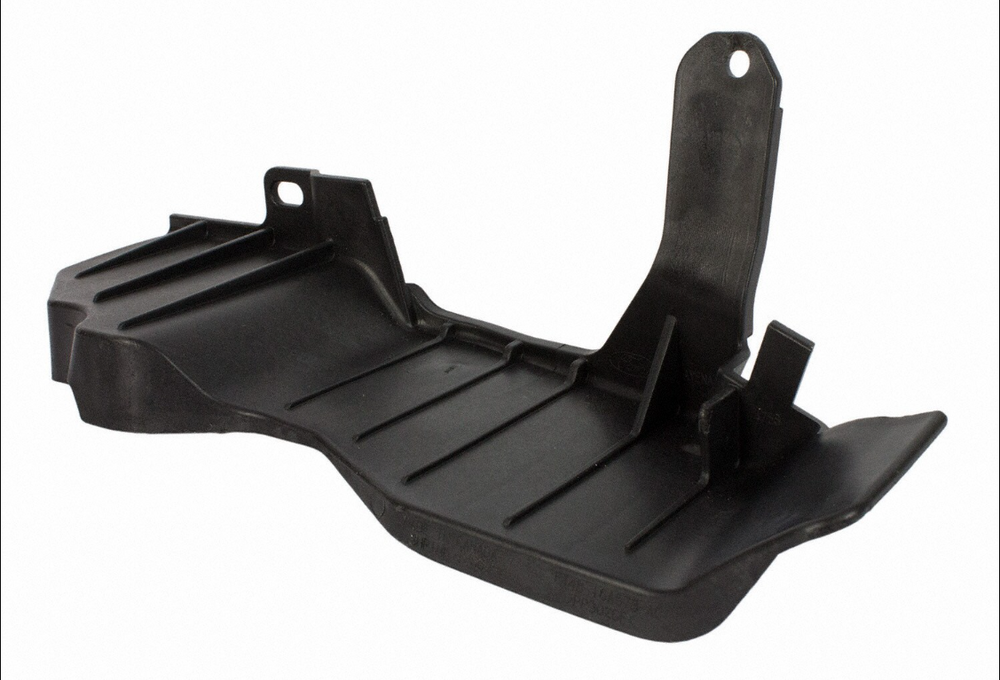
Small Plastic Shield near front right fender liner - part number?
Haz replied to 1004ron's topic in Exterior & Body
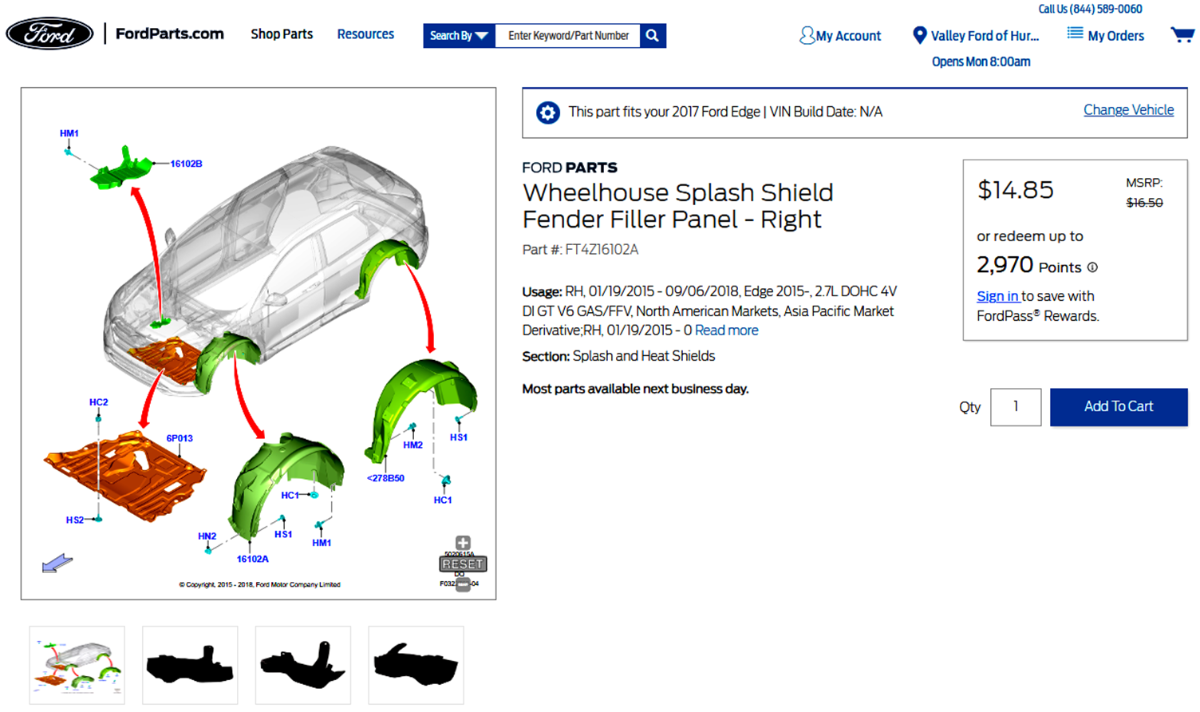
Link to this FordParts webpage Good luck!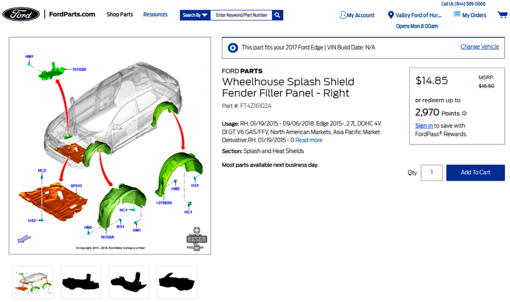

-
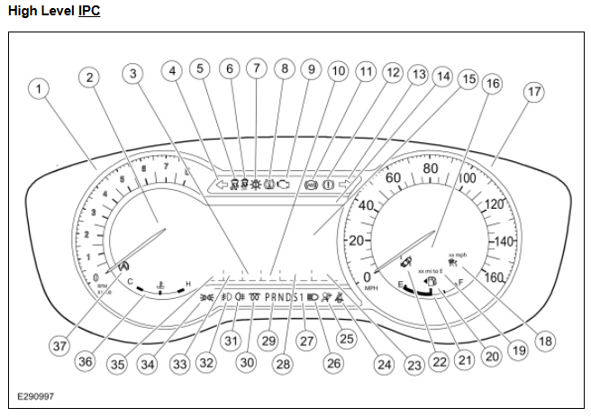
For that VIN and generally for 2020 Edge -- which is the latest listed model year shown -- no mention or depiction of AutoHold switch or circuits/connectors in the China region Wiring Resource, though the China region Workshop Manual includes identification of the Instrument Panel Cluster's AutoHold Reconfigurable TellTale (RTT) indicator lamp in an IPC illustration... ...and as you mentioned previously, a single reference to AutoHold in the China region HTML format Owner's Manual, which is the only format in which the Owner's Manual is offered... Good luck!

-
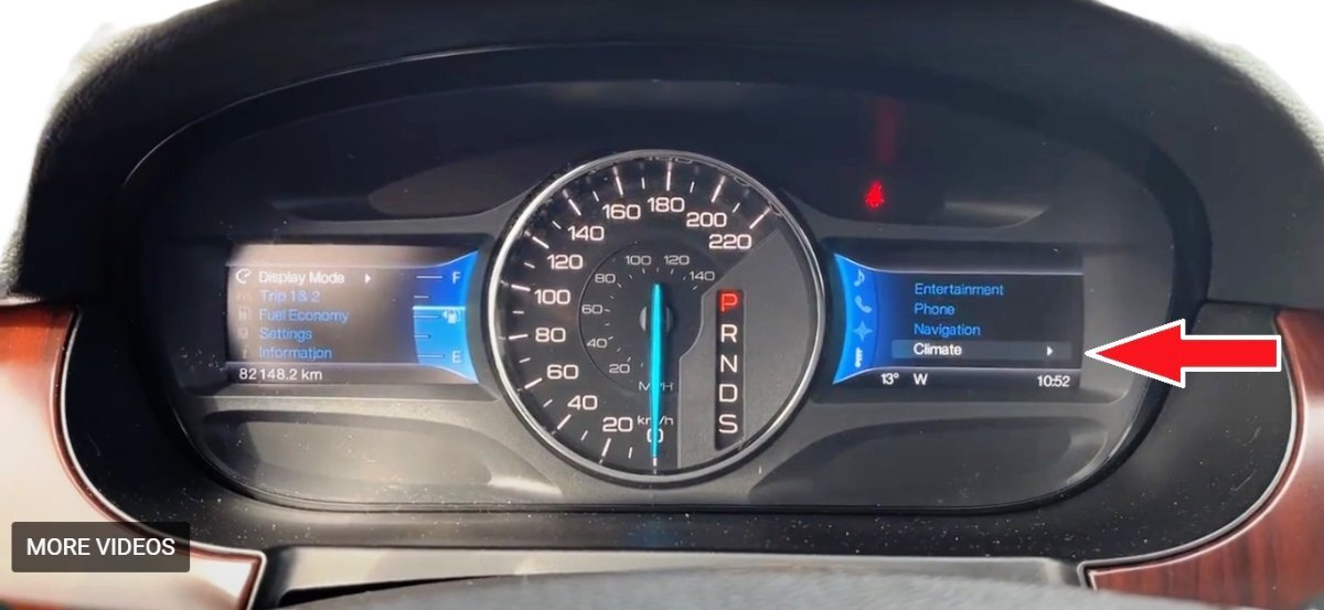
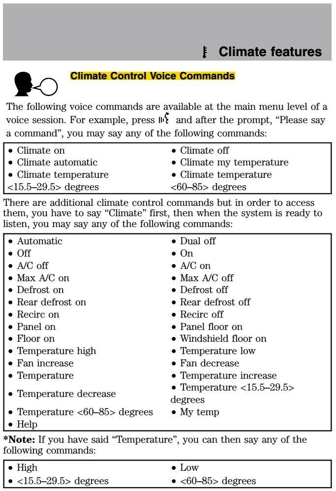
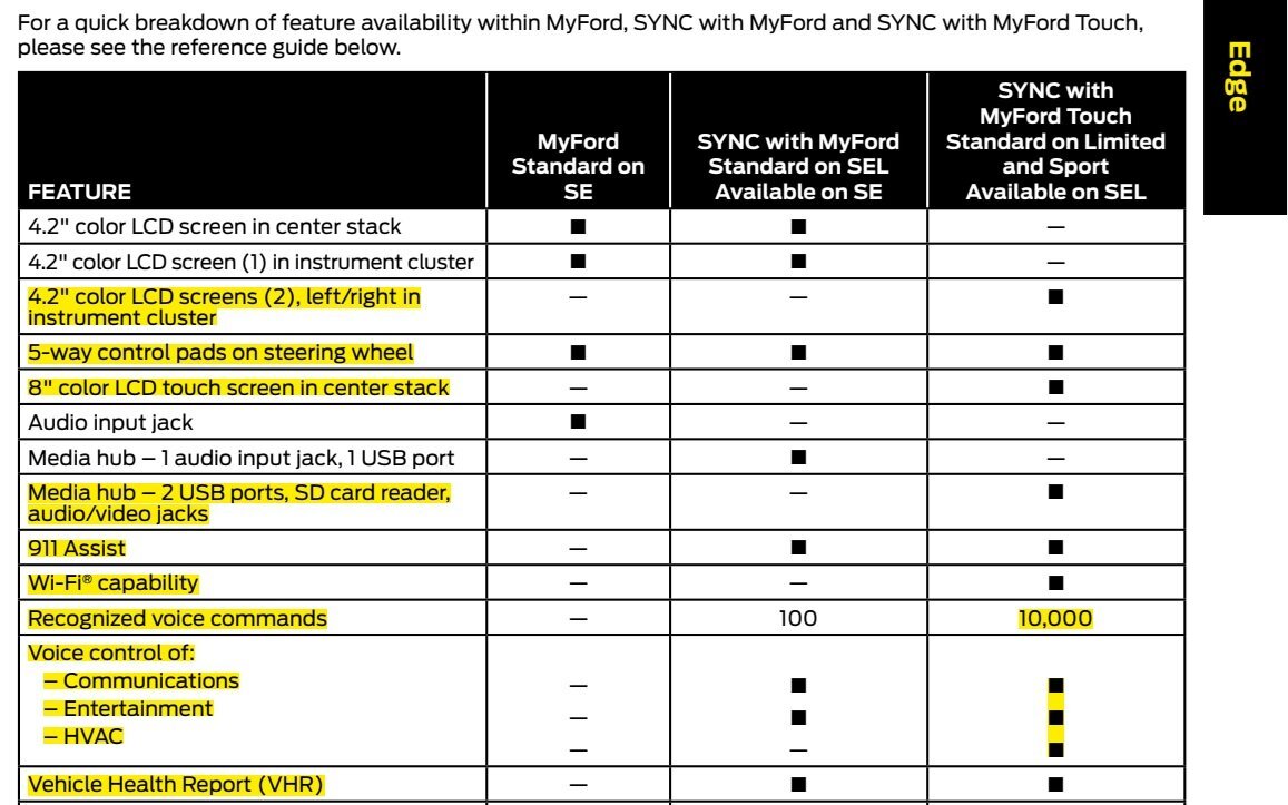
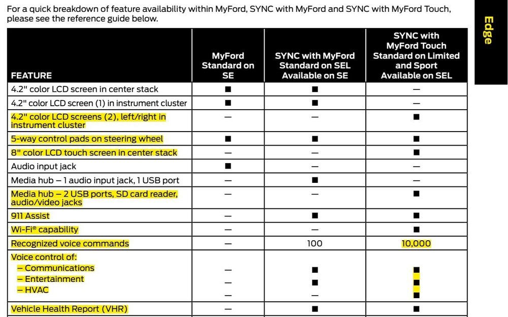
Welcome to the Forum @chisle! As you describe your 2013 Edge SEL, it should be equipped with the optional SYNC with MyFord Touch, including the features highlighted below in yellow... The expanded vocabulary of 10,000 Recognized Voice Commands includes the ability to control various HVAC functions via spoken words... hat Hopefully, you becoming proficient in the most useful of these Climate Control Voice Commands can eliminate your need to replace the Center Stack Control Panel and also reduce the distraction it has represented. Attached below as PDF documents are several references that may be helpful... Good luck! Climate Control Voice Commands - SYNC2.pdf MyFord Touch - MyLincoln Touch Supplement - Printing 4.pdf 2013 Ford Edge Source Book.pdf 2013 Ford Edge Quick Reference Guide.pdf

-
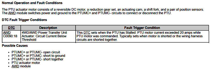
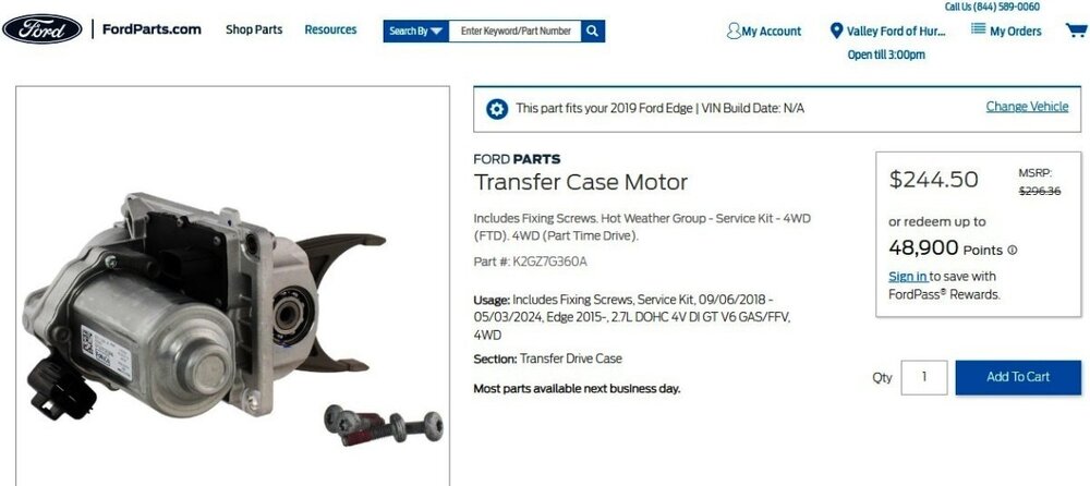
Our having the Diagnostic Trouble Code (DTC) enables us to gain fuller understanding from the 2019 Edge Workshop Manual... So, the potential failure modes involve wiring and/or connectors, the PTU Actuator Motor, or the AWD Module. The potentially involved wiring and/or connectors between the PTU Actuator Motor and the AWD Module are highlighted in yellow toward the bottom of the following Wiring Diagram... The Workshop Manual recommends performing electrical diagnostic Pinpoint Test A in order to assess which of the three failure modes - wiring/connectors, or PTU Actuator Motor, or AWD Module -- is the cause of DTC C0090:18 being set in the AWD Module. Attached below as PDF documents are Workshop Manual and Wiring Resource sections that can provide you fuller awareness of the potential work involved in addressing the diagnostic effort and the various repair procedures. Ford's online parts-selling site shows the PTU Actuator Motor... Link to this FordParts webpage It's worth noting that replacement of the PTU Actuator Motor/Transfer Case Motor involves dropping the vehicle's Front Subframe, which is a substantial task that must involve the right equipment to ensure personal safety, as detailed in the below-attached Workshop Manual procedures. Ford's Service Labor Time Standard (SLTS) for removing and installing a PTU in a 2.7L EcoBoost Edge is 6.1 hours. Replacement of the PTU Actuator Motor might involve another hour of Labor. So, Labor will be the majority of the cost if you have the job done by a professional technician at a dealership or independent repair facility. While you might undertake the electrical diagnostic procedure to personally assess wiring/connectors and the state of the PTU Actuator Motor, keep in mind that a professional technician will duplicate that task prior to replacing the PTU Actuator Motor, with the SLTS for that being 0.3-0.5 hour of Labor, which is less time than it would take me to put our 2015 MKX up in the air and safely roll underneath it. Good luck! All Wheel Drive (AWD) Module to Power Transfer Unit (PTU) - Wiring Diagram - 2019 Edge.pdf PTU Actuator Motor - Diagnostic Pinpoint Test ''A'' - 2019 Edge.pdf All Wheel Drive (AWD) Module - Connector C3841 Location - Under vehicle, right front floor pan area - 2019 Edge.pdf All Wheel Drive (AWD) Module - Connector C3841 Pinout Diagram showing Pin-Circuit Detail - 2019 Edge.pdf Power Transfer Unit (PTU) - Connector C1898C Location - Engine compartment, right hand side - 2.7L EcoBoost - 2019 Edge.pdf Power Transfer Unit (PTU) - Connector C1898C Pinout Diagram showing Pin-Circuit Detail - 2019 Edge.pdf All Wheel Drive (AWD) Module - Removal and Installation - 2019 Edge Workshop Manual.pdf Power Transfer Unit (PTU) - Actuator Motor Removal and Installation - 2019 Edge Workshop Manual.pdf Front Subframe - Removal and Installation - 2019 Edge Workshop Manual.pdf
ModuletoPowerTransferUnit(PTU)-HIGHLIGHTEDWiringDiagram-2019Edge.thumb.jpg.6563e46f34c43e63298fbbaf69243242.jpg)
-
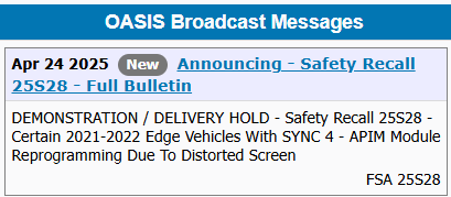
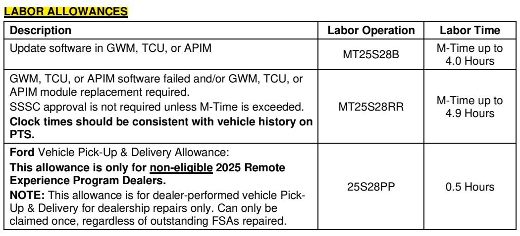
TSB 25-2157 HAS BEEN SUPERCEDED BY TSB 25-2283, WHICH IS POSTED IMMEDIATELY BELOW TECHNICAL SERVICE BULLETIN Inbound Call Cannot Be Heard And/Or Wireless Charger Icon Inaccurate 25-2157 17 April 2025 Model: Ford 2025 Explorer Lincoln 2024-2025 Nautilus 2025 Aviator Markets: North America markets only Issue: Some of the vehicles listed in the Model statement above may exhibit at least one of the following conditions: • Inbound call cannot be heard • Wireless charger icon inaccurate This may be due to the APIM software. Action: For vehicles that meet all of the criteria in the Issue and Model statements, follow the Service Procedure to reprogram the APIM. Warranty Status: Eligible under provisions of New Vehicle Limited Warranty (NVLW)/Service Part Warranty (SPW)/Service Part New Vehicle (SPNV)/Extended Service Plan (ESP) coverage. Limits/policies/prior approvals are not altered by a TSB. NVLW/SPW/SPNV/ESP coverage limits are determined by the identified causal part and verified using the OASIS part coverage tool. Labor Times Description Operation No. Time 2024-2025 Nautilus, 2025 Explorer/Aviator: Perform software update for GWM, TCU and APIM per service procedure. Includes time to clear codes. 252157A 1.9 Hrs. Additional Time For Further Updates To GWM, TCU and APIM “Refer To Warranty & Policy Manual, Section 1.3 For Time Recording Requirements And Procedures For Actual Time. Ford Monitors Module Reprogramming Vehicle History Session Data To Compare Against Warranty Claiming Activity” (Can Be Claimed With Operation A) AP252157 Actual Time Up To 2.0 Hrs. Repair/Claim Coding Causal Part: 14H522 Condition Code: 04 Service Procedure NOTE: The time required to complete this procedure varies depending on several factors including the number of module software updates required, available internet bandwidth, USB flash drive variability, and the potential that CAN flashing (software update via the DLC with FDRS) may be required. Connect to the internet with an ethernet cable, use a USB 3.2 Gen 2 or higher flash drive. When performing USB software updates, using high speed USB ports on the laptop is recommended for faster file transfer. 1. Start an FDRS session and navigate to Toolbox tab > Datalogger > body control module ( BCM) and select the BATT_SOC PID. Verify the PID reads 50% or higher. NOTE: Connecting the battery charger negative clamp directly to the battery negative terminal might result in the SOC PID not immediately reflecting the improvement from charging. (1). If SOC is less than 50%, charge the battery by attaching the battery charger's negative clamp to the engine or chassis ground and not the negative battery terminal. Refer to WSM, Section 414-01. (2). If the battery is unable to achieve a 50% SOC, use the Rotunda GRX-3590 or DCA-8000 testers to verify if replacement is required. • If the battery does not need to be replaced, disconnect the Rotunda charger and perform a BMS reset using the FDRS scan tool. • If the battery is replaced, fully charge the new battery, disconnect the Rotunda charger and perform a BMS reset using the FDRS scan tool. • Claim the battery testing and replacement outside of this article. 2. Reconnect the battery charger and set it to maintain a vehicle voltage of 12.6-13.6 volts. A low battery voltage or SOC while performing a software update to any module may result in a repeat "Restart Required" message in the vehicle's center display screen or a message on the FDRS saying "Part Number Validation Failed" or "DID Validation Failed". 3. Run the "Read The Configuration Data" app in FDRS, located in Toolbox > Multi- Module tab. 4. Navigate to the SW Updates tab. Is there a software update available for any of the following modules? GWM TCU APIM (1). Yes - proceed to Step 5. (2). No - this article does not apply. 5. Prepare to update the software for the GWM, TCU, and APIM. (1). A 64GB or larger USB flash drive is required for GWM, TCU, and APIM software updates. USB 3.2 Gen 2 or higher is recommended for faster file transfer on both the computer port and the USB drive. (2). Make sure the USB flash drive being used is formatted correctly. To see the available drives, hold down the Windows icon keyboard key and press the E keyboard key. Right click on the USB flash drive and select Properties. If File System under the General tab is not exFAT, the drive must be formatted. (3). To format the USB flash drive: • Right click on the USB flash drive. • Select Format, select exFAT for the File System. • Select Default Allocation Size for the Allocation Unit Size. (4). De-selecting Quick Format is not necessary and results in a lengthier operation. 6. Using the FDRS, begin module programming by selecting the "SW Updates" tab. Follow all on-screen instructions carefully. 7. When prompted, connect the USB flash drive to the FDRS. 8. When prompted by the FDRS, safely remove/eject the USB flash drive from the FDRS. Start the vehicle ( KOER) then connect the USB flash drive to the USB media hub to install the software into the module. When the USB software update begins, the center display screen displays a message stating "Do Not Remove USB". The update may take 10 minutes or longer to complete. NOTE: It may take up to 5 minutes for the vehicle to recognize the USB flash drive with software update. 9. When the vehicle's center display screen prompts to restart the vehicle: (1). Turn the vehicle OFF. (2). Wait 10 minutes. (3). Restart the vehicle (KOER). The update is still in process at this time. 10. Follow FDRS on-screen prompts to complete the update. NOTE: It may take up to 5 minutes before "Update Successful" appears in the vehicle's center display screen. After 5 minutes if "Update Successful" pop-up is not shown on the center display screen, remove the USB flash drive and select YES on the FDRS prompt stating "Was The USB Update Successful" ( FDRS verifies if the module software update was successfully installed on the module). 11. Perform the software update for the GWM. Follow all update screens. If there is no GWM software update available, proceed to Step 12. (1). If there is no screen prompt indicating that the software update is in progress: • Perform the Digital Experience reset. (2). Follow the center display screen prompts. (3). Follow FDRS prompts to complete the GWM programming. • Once the pop up stating "Update Successful" appears in the center display screen, select Close, remove the USB flash drive from the USB media hub, and select Yes on FDRS indicating the update installed successfully. This initiates the remaining automated configuration steps and reports the module software part numbers and application software levels to the Ford online database. Failure to follow this step results in an inaccurate database as well as omitted, improperly installed, or improperly configured applications (features) such as navigation (if equipped). It is normal for the module to reset during this step. (4). Proceed to Step 12. 12. Perform the software update for the TCU. Follow all update screens. If there is no TCU software update available, proceed to Step 13. (1). If there is no screen prompt indicating that the software update is in progress: • Perform the Digital Experience reset. (2). Follow the center display screen prompts. (3). Follow FDRS prompts to complete the TCU programming. • Once the pop up stating "Update Successful" appears in the center display screen, select Close, remove the USB flash drive from the USB media hub, and select Yes on FDRS indicating the update installed successfully. This initiates the remaining automated configuration steps and reports the module software part numbers and application software levels to the Ford online database. Failure to follow this step results in an inaccurate database as well as omitted, improperly installed, or improperly configured applications (features) such as navigation (if equipped). It is normal for the module to reset during this step. (4). Proceed to Step 13. 13. Perform the software update for the APIM. Follow all update screens. If there is no APIM software update available, proceed to Step 14. (1). If there is no screen prompt indicating that the software update is in progress: • Perform the Digital Experience reset. (2). Follow the center display screen prompts. (3). Follow FDRS prompts to complete the APIM programming. • Once the pop up stating "Update Successful" appears in the center display screen, select Close, remove the USB flash drive from the USB media hub, and select Yes on FDRS indicating the update installed successfully. This initiates the remaining automated configuration steps and reports the module software part numbers and application software levels to the Ford online database. Failure to follow this step results in an inaccurate database as well as omitted, improperly installed, or improperly configured applications (features) such as navigation (if equipped). It is normal for the module to reset during this step. (4). Proceed to Step 14. 14. Format the USB drive. Right click on the USB flash drive. Select Format, select exFAT for the File System. Select Default Allocation Size for the Allocation Unit Size. De-selecting Quick Format is not necessary and results in a lengthier operation. NOTE: The USB drive must be formatted immediately after the APIM software update (prior to updating any other module) or the subsequent updates may fail. 15. Refresh the FDRS files. (1). Click on envelope icon. (2). Select Refresh FDRS Files (this will close FDRS when completed). (3). Launch FDRS. (4). Start new FDRS session. 16. Are there any updates available for the GWM, TCU, and/or APIM? NOTE: The option to update a module may not be available until other module(s) are updated to a certain level. The network test is a confirmation that all modules are at the latest available software. Some repairs may require multiple network tests to reveal all module dependent software. (1). Yes - proceed to Step 11. (2). No - repair is complete. © 2025 Ford Motor Company All rights reserved. NOTE: The information in Technical Service Bulletins is intended for use by trained, professional technicians with the knowledge, tools, and equipment to do the job properly and safely. It informs these technicians of conditions that may occur on some vehicles, or provides information that could assist in proper vehicle service. The procedures should not be performed by "do-it-yourselfers". Do not assume that a condition described affects your car or truck. Contact a Ford or Lincoln dealership to determine whether the Bulletin applies to your vehicle. Warranty Policy and Extended Service Plan documentation determine Warranty and/or Extended Service Plan coverage unless stated otherwise in the TSB article. The information in this Technical Service Bulletin (TSB) was current at the time of printing. Ford Motor Company reserves the right to supersede this information with updates. The most recent information is available through Ford Motor Company's on-line technical resources.
- 1 reply
-
- 3
-

-
SSM 53653 2024-2025 Nautilus - Temporary Diagnostic Trouble Code (DTC) U2404 After Programming The Gateway Module (GWM) Some 2024-2025 Nautilus vehicles may exhibit a temporary U2404 DTC after programming the gateway module (GWM). This DTC will clear itself after 10 minutes of ignition off time. Additional programming or module replacement will not resolve the condition. If the DTC is still present after 10 minutes, diagnose using normal Workshop Manual (WSM) diagnostics.
-
@DBEDGE23: The 2016 2.7L EcoBoost Workshop Manual documents attached immediately-above also apply to your 2015 2.7L EcoBoost Edge Sport. Ford Service Time Labor Standard - 2015 Edge AWD Gasket Set or Oil Pan (In Chassis) (6675/ 6710/ 6781) - Remove and Install or Replace - 2.7L EcoBoost = 3.1 hours Includes clean internally mounted oil pump pick-up tube and screen and replace oil filter when directed by workshop manual. Good luck!
-
Odd Electronic Behavior (Proximity Sensors and Door Locks)
Haz replied to DNBush's topic in 2019-Current Edge & Nautilius
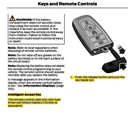
@DNBush: From the 2020 Edge Workshop Manual... Placing your device cursor over underlined acronyms may yield popup full-words descriptions of the acronyms. Switch Inhibit Feature The switch inhibit feature prevents unauthorized access to the vehicle from the door lock control switches or the liftgate release switch. The BCM disables the function of both door lock control switches and the interior liftgate release switch 20 seconds after the vehicle is electronically locked. If any of these switches are activated while they are inhibited, a chime sounds and a message is displayed in the message center to indicate the switches are inhibited. The BCM enables the function of these switches when the vehicle is electronically unlocked. This feature can be configured on/off through the message center. Passive Entry (if equipped) NOTE: To perform an accurate diagnosis of a concern, make sure the vehicle has a fully charged 12V battery and is in good condition when performing any electrical pinpoint tests. When the vehicle’s 12-volt battery is below a set threshold, certain features can be limited or become inoperative and lead to misdiagnosis. NOTE: Some models are not equipped with the passive entry feature, but are equipped with push button start. The passive entry feature unlocks or locks the doors or opens the liftgate without having to use a mechanical key blade or the RKE transmitter feature. When the BCM detects a lock or unlock sensor is touched on an exterior door handle, or the exterior liftgate release button is pressed, it activates the low frequency antenna in the corresponding exterior door handle or inside the luggage compartment area. The low frequency antenna sends out a signal to activate the passive key. The passive key then responds by sending a high frequency signal back to the RTM . The RTM interprets the high frequency signal from the passive key and sends the information to the BCM . If the BCM detects a valid programmed passive key, the BCM unlocks the driver door, unlocks or locks all 4 doors, releases the liftgate latch (manual liftgate) or sends a command to the RGTM to power open the liftgate (power liftgate). The passive entry (Intelligent Access) feature is part of vehicle load shed strategy. Door Passive Entry With a programmed passive key within 1 m (3.28 ft) outside a door, touch the lock or unlock sensor on the exterior door handle. The doors lock or unlock depending upon which sensor was touched on the handle. The unlock button is located on the inside of the handle and the lock button is located on the outside top face of the handle. The driver front door passive entry feature either unlocks the driver door (if 2-stage unlock is enabled) or all four doors (if 2-stage unlock is disabled). The passive entry feature always locks all four doors when the lock button is touched. The remaining doors passive entry feature always locks or unlocks all four doors. Some vehicles with the SE option may not be equipped with the rear doors passive entry feature. Because the door handle touch symptom is intermittent -- if you have not already -- you may want to try putting a new battery in your Intelligent Access Key... Good luck! Handles, Locks, Latches and Entry Systems - System Operation and Component Description - 2020 Edge Workshop Manual.pdf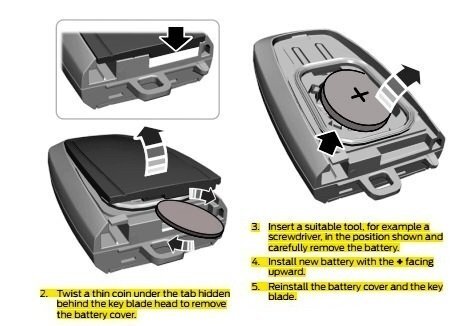
-
Welcome to the Forum @w102acd! From the 2019 Edge Workshop Manual, with emphasis added... Placing your device cursor over underlined acronyms may yield popup full-words descriptions of the acronyms. Spare Tire And Mismatched Tire Sizes Major dissimilar tire sizes between the front and rear axles could cause the AWD system to stop functioning and default to FWD or damage the AWD system. It is recommended to reinstall a repaired or replaced road tire as soon as possible. When a mismatched or tire of the wrong size is fitted, an AWD OFF message may appear in the IPC . If this condition occurs, a DTC is set and an AWD OFF message is displayed on the message center. If there is an AWD malfunction service required message in the message center from using a spare or mismatched tire, this indicator should turn off after reinstalling a tire of the same size as the normal road tire, then cycling the ignition OFF and ON. AWD Control And Fault Indicators The AWD system consists of a Power Transfer Unit (PTU), driveshaft, front and rear halfshafts, AWD module, RDU with integral RDU coupling. The systems uses the AWD module for AWD control logic. Using inputs from various modules and systems, when the power transfer unit is engaged the AWD module sends a command to the RDU which controls the amount of torque applied to the to the rear wheels. AWD system faults are indicated by a driveline icon indicator in the IPC as well as the AWD malfunction service required message in the message center. The following is Workshop Manual guidance on retrieving AWD-related Diagnostic Trouble Codes (DTCs)... Inspection and Verification NOTE: For most AWD System DTCs to set, the AWD module must detect the fault on 2 consecutive trips. 1) Record and clear DTCs from the AWD module. 2) Accelerate the vehicle from 0-45 mph with light (10%) APP. 3) Maintain 45 mph for 10 seconds. 4) Gently slow to a stop. 5) Repeat steps 2-4. 6) Accelerate the vehicle from 0-45 mph with moderate (30%) APP. 7) Maintain 45 mph for 10 seconds. 8) Gently slow to a stop. 9) Repeat steps 6-8. 10) Turn off ignition, wait 1 minute. 11) Repeat steps 2-9 or until an AWD fault message is displayed in the IPC . Whichever is sooner. 12) Retrieve continuous memory DTCs from the AWD module. If no DTCs are present, the concern may be intermittent. Do not perform a pinpoint test unless the concern is present. Good luck! Four-Wheel Drive Systems - Overview - 2019 Edge Workshop Manual.pdf Four-Wheel Drive Systems - System Operation and Component Description - 2019 Edge Workshop Manual.pdf
-
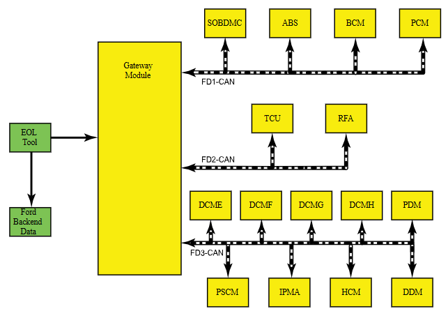
SSM 53638 - 2023-2025 Various Vehicles - Trusted Real-Time Operation Network (TRON) Module Authentication DTCs After Module Replacement - Workshop Manual Update After replacement of any TRON module, the gateway module (GWM) and the TRON capable modules can set diagnostic trouble codes (DTCs) U211A, U211B, U211C, U3034, U3035, U3036, U35D9, U35DA and/or U35DB if the secret authentication security keys are not aligned between the modules, a loss of communication is occurring between modules and/or a module is not responding. This may be a result of missing the new module secret authentication security key obtained when running the Ford Diagnosis and Repair System (FDRS) "Trusted Real-Time Operation Network (TRON) Module Authentication" procedure after replacement. When replacing a TRON capable module, run the FDRS "Trusted Real-Time Operation Network (TRON) Module Authentication" procedure to distribute a new set of secret authentication security keys to all TRON-capable modules. Using the specific VIN, refer to Workshop Manual (WSM), Section 418-00 and 418-01 for updated DTCs, applicable TRON module listings and pinpoint tests. From the 2024-2025 Nautilus Workshop Manual... Placing your device cursor over underlined acronyms may yield popup full-words descriptions of the acronyms. Trusted Real-Time Operation Network (TRON) - System Operation and Component Description System Operation Overview Trusted Real-Time Operation Network (TRON) is a cyber security protocol applied to certain modules connected to the vehicle communication networks. This protocol provides a digital message authentication for data being communicated between modules on the networks, to make sure the data received by a module is the data sent by the sending module and has not been interrupted or tampered with by an outside source. System Diagram Trusted Real-Time Operation Network (TRON) Trusted Real-Time Operation Network (TRON) secret data authentication security keys are applied to modules with motion control, safety critical and security critical functions. Not all modules on the vehicle will have data authentication security keys applied. The secret authentication security keys provide a digital data handshake between the sending module and the receiving module to confirm the data received has been sent by the expected source. The initial secret authentication security key distribution takes place at the end of the production line, prior to the vehicle release to the dealer. The key update mechanism includes a key management client and key management server modules. The key management client is the GWM and the key management server modules are the modules participating in the TRON function. The GWM generates the keys and distributes them to itself and the server modules, one module at a time sequentially. The keys are processed by the receiving modules and stored in their memory and a backup of the distributed keys is stored in the TCU . After the vehicle's TRON has been successfully configured, the production line end of line tool sends a copy to the Ford backend data systems for storage. If a TRON-capable module is replaced, the module secret authentication security key must be applied to the new module so it functions on the network when installed. When replacing a TRON capable module, run the FDRS Trusted Real-Time Operation Network (TRON) Module Authentication Diagnosis and Repair procedure to distribute a new set of secret authentication security keys to all TRON-capable modules. The GWM and the TRON capable modules can set Diagnostic Trouble Codes (DTCs) if the keys are misaligned between modules, there are communication issues on the vehicle network or a module is not responding. Component Description Gateway Module The GWM acts as the key management client for the Trusted Real-Time Operation Network (TRON) system for creating, monitoring and distributing the secret keys to the participating modules. Telematic Control Unit Module The TCU stores a backup of all Trusted Real-Time Operation Network (TRON) distributed keys.
-
Attached below as a PDF document is the Timing Belt R & I procedure for the 2.0L Duratorq-TDCi (132kW/180PS), which is identical to the procedure for the 2.0L Duratorq-TDCi (150kW/204PS)... Good luck! Timing Belt - Removal and Installation - 2.0L Duratorq-TDCi (132kW-180PS) - 2015-2022 Edge, Edge Vignale, Endura Workshop Manual.pdf Engine - Component Location - 2.0L Duratorq-TDCi - 2015-2022 Edge, Edge Vignale, Endura Workshop Manual.pdf Specifications - 2.0L Duratorq-TDCi (132kW-180PS) - 2015-2022 Edge, Edge Vignale, Endura Workshop Manual.pdf Specifications - 2.0L Duratorq-TDCi (150kW-204PS) - 2015-2022 Edge, Edge Vignale, Endura Workshop Manual.pdf
-
Ford's online United Kingdom Workshop Manual denotes its Model Year & Model coverage in this way... and its Engine coverage in this way... Attached below as PDF documents are the Timing Belt and Timing Cover workshop manual sections covering the lower-output 2.0L EcoBlue (88kW/120PS) (YN)/2.0L EcoBlue (110kW/150PS) (YM)/2.0L EcoBlue (140kW/190PS) (BC) engines... Good luck! Timing Belt - Removal and Installation - 2.0L EcoBlue (88kW-120PS) (YN) - 2.0L EcoBlue (110kW-150PS) (YM) - 2.0L EcoBlue (140kW-190PS) (BC) - 2015 - 2022 Edge, Edge Vignale, Endura Workshop Manual.pdf Timing Cover - Removal and Installation - 2.0L EcoBlue (88kW-120PS) (YN) - 2.0L EcoBlue (110kW-150PS) (YM) - 2.0L EcoBlue (140kW-190PS) (BC) - 2015 - 2022 Edge, Edge Vignale, Endura Workshop Manual.pdf


-
REAR LIFTGATE TRUNK RELEASE SWITCH-BUTTON
Haz replied to silverknight's topic in Alarms, Keyless Entry, Locks & Remote Start
Leveraging from the bottom would be best, due to the midpoint retaining tabs on either side and the locator/pivot tab at the top. Likely because of this simplicity, the GEN 1 & GEN 2 Edge/MKX/Nautilus Workshop Manuals do not provide any removal and installation procedure, though there is a electrical diagnostic Pinpoint Test covering the front & rear Power Liftgate switches, if that interests you. Good luck!