Haz
-
Posts
1,568 -
Joined
-
Last visited
-
Days Won
439
Content Type
Profiles
Forums
Gallery
Everything posted by Haz
-
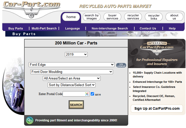
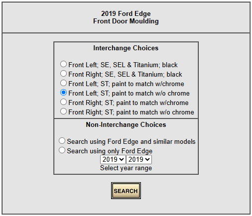
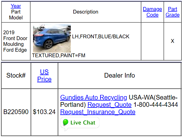
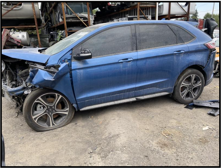
Welcome to the Forum @Huntk420! Surprisingly rare -- the only one -- via online Salvage Yard search engine Car-Part.com... 2019 Edge ST Paint Color: Ford Performance Blue Paint Code: FM Build Date: 10/19/2018 Link - Gundie's Auto Recyclers Link - Vehicle Images Good luck!
-
2024 Edge rattle noise from rear cargo trim panel
Haz replied to lasseventies's topic in 2.0L EcoBoost
@STBEAST: From the 2022-2024 Edge Workshop Manual... Good luck! Loadspace Trim Panel - Removal and Installation - 2022-2024 Edge Workshop Manual.pdf -
Excessive smoke on cold start - 2017 Ford Edge Sport 2.7l
Haz replied to JohnR0983's topic in 2.7L EcoBoost
Relevant sections from the 2017 Edge Workshop Manual are attached below as PDF documents... Good luck! Turbocharger Oil Supply Tube LH - Removal and Installation - 2.7L EcoBoost - 2017 Edge Workshop Manual.pdf Generator - Removal and Installation - 2.7L EcoBoost - 2017 Edge Workshop Manual.pdf Air Conditioning (A-C) Compressor - Removal and Installation - 2.7L EcoBoost - 2017 Edge Workshop Manual.pdf Air Conditioning (A-C) System Recovery, Evacuation and Charging - Overview of General Procedures - 2017 Edge Workshop Manual.pdf Catalytic Converter LH - Removal and Installation - 2.7L EcoBoost - 2017 Edge Workshop Manual.pdf Exhaust Flexible Pipe - Removal and Installation - 2.7L EcoBoost - 2017 Edge Workshop Manual.pdf Specifications - 2.7L EcoBoost - 2017 Edge Workshop Manual.pdf Turbocharger Oil Return Tube LH - Removal and Installation - 2.7L EcoBoost - 2017 Edge Workshop Manual.pdf Turbocharger Oil Return Tube RH - Removal and Installation - 2.7L EcoBoost - 2017 Edge Workshop Manual.pdf Turbocharger Oil Supply Tube RH - Removal and Installation - 2.7L EcoBoost - 2017 F-150 Workshop Manual.pdf Air Cleaner Outlet Pipe RH - Removal and Installation - 2.7L EcoBoost - 2017 Edge Workshop Manual.pdf -
Excessive smoke on cold start - 2017 Ford Edge Sport 2.7l
Haz replied to JohnR0983's topic in 2.7L EcoBoost
From the 2017 Edge Workshop Manual... Pinpoint Tests PINPOINT TEST A: BLUE SMOKE FROM EXHAUST Introduction Possible Causes Oil leak Air cleaner Air intake Crankcase ventilation system Internal engine damage Turbocharger A1 CHECK THE EXHAUST Start the engine. Monitor the exhaust system. Is blue smoke noticeable from the exhaust system? Yes GO to A2 No INSPECT for external oil leaks. REFER to 303-00 Engine System, Oil Leak Inspection for the engine being diagnosed. A2 CHECK THE AIR CLEANER Inspect the air cleaner. Is the air cleaner clogged? Yes REPLACE the air cleaner. REFER to 303-12 Intake Air Distribution and Filtering for the engine being diagnosed. CHECK the system for normal operation. No GO to A3 A3 CHECK THE AIR INTAKE PIPES AND HOSES Inspect the air intake pipes and hoses for loose connections or leaks. Were any loose connections or leaks found from the air intake pipes or hoses? Yes REPAIR or REPLACE the intake air system. REFER to 303-12 Intake Air Distribution and Filtering for the procedure. No GO to A4 A4 CHECK THE CRANKCASE VENTILATION SYSTEM Check the crankcase ventilation system for damage and correct operation. Refer to 303-08 Engine Emission Control, Diagnosis and Testing for the engine being diagnosed. Is the crankcase ventilation system damaged? Yes CLEAN, REPAIR or REPLACE the crankcase ventilation components. REFER to section 303-08 Engine Emission Control for the procedure. No GO to A5 A5 CHECK THE AIR INTAKE PIPES AND HOSES FOR EXCESSIVE OIL NOTE: It is normal for a small amount of combustion gas to pass into the crankcase. This gas is scavenged into the air intake system through the positive crankcase ventilation system, which incorporates a crankcase vent oil separator. Some engine oil, in the form of a vapor, is carried into the air intake system with the blow-by gases (this engine oil also contributes to valve seat durability). This means that oil will collect inside the air intake components and the turbocharger. This is not an indication that the turbocharger oil seal has failed. The turbocharger oil seal will generally not fail unless the bearings fail first, which will cause the turbocharger to become noisy or seize. Do not install a new turbocharger due to oil inside the intake. Inspect the inside of the air intake pipes and hoses for excessive oil. Is excessive oil noticeable? Yes GO to A6 No DIAGNOSE internal engine damage. REFER to 303-00 Engine System, Diagnosis and Testing for the engine being diagnosed. FOLLOW the pinpoint test to diagnose blue smoke. A6 CHECK THE TURBOCHARGER Remove the air cleaner outlet pipe and CAC intake pipe. Refer to 303-12 Intake Air Distribution and Filtering for the procedure. Inspect the compressor wheel for damage. Check that the turbine shaft spins free. Check for contact marks between the compressor wheel and the housing. Is the turbocharger damaged? Yes INSTALL a new turbocharger. REFER to 303-04 Fuel Charging and Controls - Turbocharger for the procedure. No Diagnose internal engine damage. REFER to 303-00 Engine System, Diagnosis and Testing for the engine being diagnosed. FOLLOW the pinpoint test to diagnose blue smoke. Good luck! Engine Fuel Charging and Controls - 2.7L EcoBoost - Diagnostic Pinpoint Test A - 2017 Edge Workshop Manual.pdf Positive Crankcase Ventilation (PCV) Valve - Removal and Installation - 2.7L EcoBoost - 2017 F-150 Workshop Manual.pdf-Black-Blue-WhiteSmoke-2017EdgeWorkshopManual.jpg.bac7e83c5e357cb65f4860609cf1c867.jpg)
-
Link to moulding clips sold by Advance Auto Parts Link to Advance Auto Parts store locator Good luck!
-
@STBEAST: 2024 Ford Edge Owner's Manual (PDF direct download link) Good luck!

-
@Wubster100: RF Keypad information, attached below as PDF documents... Good luck! Wireless RF Key Pad Instructions - 2020-Current Model Year - Ford Accessories.pdf Wireless RF Key Pad Quickstart Guide - August 2024 - Ford Accessories.pdf Wireless RF Key Pad Diagnosis - April 2022 - Ford Accessories.pdf
-
Looking at the 2021 Edge ST's history, it appears its previous DSP update did not occur through a dealership visit, so it may have been Over-The-Air (OTA), like the January 2025 SYNC4 update which is clearly identified as OTA. How long this vehicle has been waiting to receive its presently available DSP update is not clear, since I cannot view the 2021 Edge's Connected Vehicle status, which shows a 60-day history. If you are not a FordPass user, you may want to explore its capabilities. OTA software updates can sometimes become stalled as a result of unsuccessful update actions toward other prerequisite modules. The surest way to navigate multiple-module updates is to have the dealer connect the vehicle to Ford's software update server, which assesses and properly sequences the software updates. If problems arise, then the dealership can contact the Dealer Software Support Hotline (DSSH) for guidance to overcome the problem. Good luck!
-
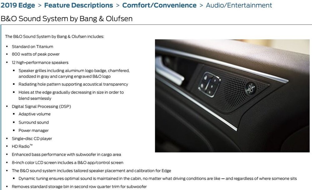
Welcome to the Forum @jonasy! It's possible that the two 2019 Edge STs do not have the same software level in their B&O 12-speaker audio system's Audio Digital Signal Processing (DSP) modules. While I'm unable to remotely view DSP software levels in 2019 model year vehicles, I checked the DSP software level in a B&O-equipped 2021 Edge ST with its last DSP update (JL3T-14C589-EA) having occurred in September 2021, and a DSP update is presently available for that specific vehicle. In the case of the 2019 Edge STs, one vehicle may have received a DSP software update that the other vehicle has not yet received. The DSP module is located behind the Driver's Side (Left Hand) Cargo Loadspace trim panel... Good luck!


-
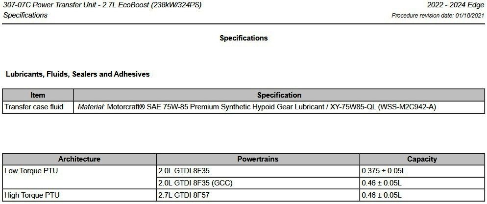
@STBEAST: From the 2022-2024 Edge Workshop Manual, including Power Transfer Unit (PTU) drain & fill procedure attached below as a PDF document... Good luck! Power Transfer Unit Draining and Filling - 2.7L EcoBoost - General Procedures - 2022-2024 Edge Workshop Manual.pdf
-
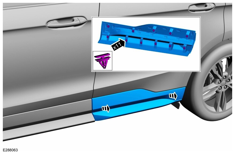
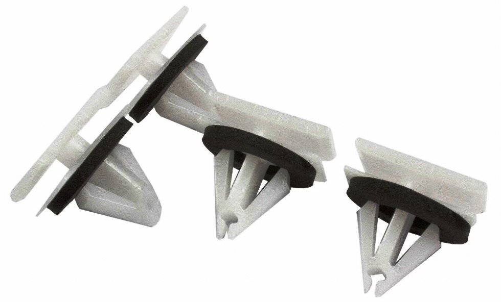
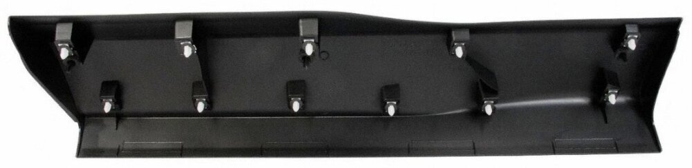
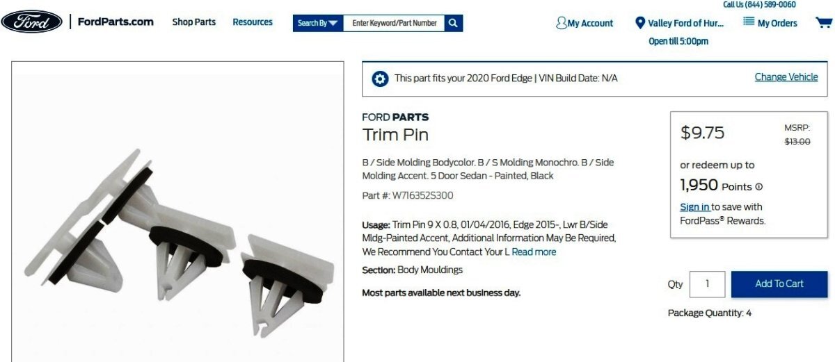
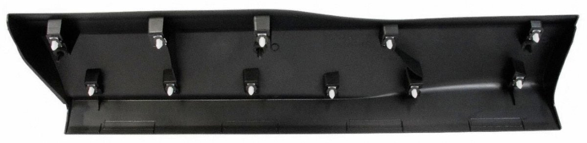
Welcome to the Forum @Kellmac! The 2020 Edge Workshop Manual indicates the Rear Door Moulding panel is retained to the body by eleven (11) clips attached to the panel's molded-in pedestals. You might try putting a square of masking tape or low-tack painter's tape on the outer face of the panel corresponding to each of the eleven pedestals, to ensure that you are directly engaging each and every retaining clip. If any of your Edge's clips appear to be damaged when compared to the below photo, replacement clips are available per Ford's online parts-selling site, and through your local dealer's Parts Department. And finally, the 2020 Edge Workshop Manual removal & installation procedure is attached below as a PDF document. Good luck! Link to this FordParts webpage Rear Door Moulding - Removal and Installation - 2020 Edge Workshop Manual.pdf

-
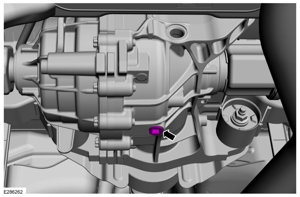
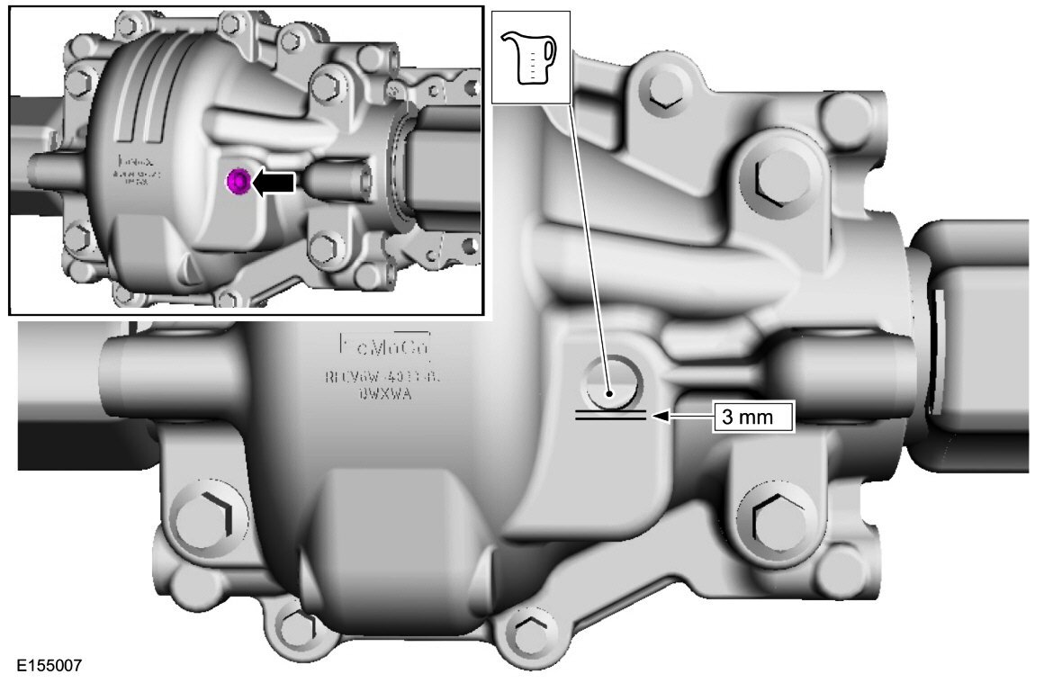
2015-2018 Edge Workshop Manual - Rear Differential Unit (RDU) - Filler Plug ONLY 2019-2024 Edge Workshop Manual - Rear Drive Unit (RDU) - Filler Plug 2019-2024 Edge Workshop Manual - Rear Drive Unit (RDU) - Drain Plug 2007-2014 Edge Workshop Manual - Rear Differential Unit (RDU) - Filler Plug ONLY Good luck!


-FillerPlugONLY.thumb.jpg.909f0bcf4eef17868eb2a4ad32637852.jpg)


-
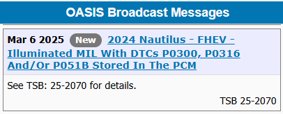
TECHNICAL SERVICE BULLETIN Illuminated MIL With DTCs P0300, P0316 And/Or P051B Stored In The PCM 25-2070 05 March 2025 This bulletin supersedes 24-2319. Reason for update: change labor operation from actual time to fixed time Model: Lincoln 2024 Nautilus FHEV Markets: North American markets only Issue: Some of the vehicles listed in the Model statement above may exhibit an illuminated MIL with DTCs P0300, P0316 and/or P051B stored in the PCM. This may be due to the software level of the PCM and the SOBDMC. Action: For vehicles that meet all of the criteria in the Issue and Model statements, follow the Service Procedure to reprogram the PCM and SOBDMC to the latest software level. Warranty Status: Eligible under provisions of New Vehicle Limited Warranty (NVLW)/Emissions Warranty/Service Part Warranty (SPW)/Service Part New Vehicle (SPNV)/Extended Service Plan (ESP) coverage. Limits/policies/prior approvals are not altered by a TSB. NVLW/Emissions Warranty/SPW/SPNV/ESP coverage limits are determined by the identified causal part and verified using the OASIS part coverage tool. Labor Times Description Operation No. Time 2024 Nautilus FHEV - Perform Software Update For PCM And SOBDMC Following TSB Procedure. (Do Not Use With Any Other Labor Operations) 252070A 0.4 Hrs. Repair/Claim Coding Causal Part: RECALEM Condition Code: 04 Service Procedure 1. Connect a battery charger such as Rotunda GRX-3590 or DCA-8000 to the 12-volt battery. NOTE: To prevent the battery saver mode from activating on the vehicle, make sure the negative cable of the charger is installed on a chassis or engine ground, and not the 12-volt battery negative terminal. Do not have the vehicle plugged into high voltage battery charger during programming. This can cause incorrect module programming. Make sure only the 12-volt battery charger is installed. 2. Reprogram the PCM and SOBDMC using the latest level software level of the FDRS scan tool. NOTE: Advise the customer this vehicle is equipped with an adaptive transmission shift strategy which allows the vehicle's computer to learn the transmission's unique parameters and improve shift quality. When the adaptive strategy is reset, the computer will begin a relearning process. This relearning process may result in firmer than normal upshifts and downshifts for several days. © 2025 Ford Motor Company All rights reserved. NOTE: The information in Technical Service Bulletins is intended for use by trained, professional technicians with the knowledge, tools, and equipment to do the job properly and safely. It informs these technicians of conditions that may occur on some vehicles, or provides information that could assist in proper vehicle service. The procedures should not be performed by "do-it-yourselfers". Do not assume that a condition described affects your car or truck. Contact a Ford or Lincoln dealership to determine whether the Bulletin applies to your vehicle. Warranty Policy and Extended Service Plan documentation determine Warranty and/or Extended Service Plan coverage unless stated otherwise in the TSB article. The information in this Technical Service Bulletin (TSB) was current at the time of printing. Ford Motor Company reserves the right to supersede this information with updates. The most recent information is available through Ford Motor Company's on-line technical resources.
- 1 reply
-
- 1
-

-
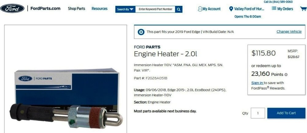
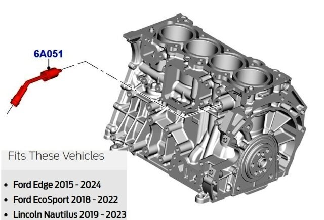
SSM 53474 2019-2024 Edge, 2019-2023 Nautilus - 2.0L - Repeat Block Heater Failure - Updated Procedure In The Workshop Manual (WSM) Some 2019-2024 Edge and 2019-2023 Nautilus vehicles equipped with a 2.0L engine may exhibit a repeat block heater failure. This may be caused by air in the engine cooling system. The WSM replacement procedure has been updated to include the Engine Cooling System Draining, Vacuum Filling and Bleeding procedure found in Section 303-03A Engine Cooling - 2.0L EcoBoost (184kW/250PS) - MI4, General Procedures as the final step. The block heater should not be tested unless all the air has been removed from the engine cooling system following this procedure. Relevant Workshop Manual sections, as PDF documents, are attached below a Workshop Manual illustration and information from Ford's online parts-selling site... Link to this FordParts webpage Block Heater - 2.0L EcoBoost - Removal and Installation - Edge-Nautilus Workshop Manual.pdf Engine Cooling System Draining, Vacuum Filling and Bleeding - 2.0L EcoBoost - General Procedures - Edge-Nautilus Workshop Manual.pdf
-
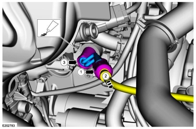
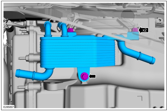
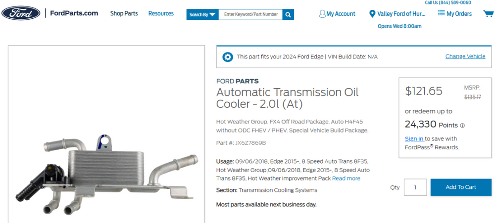
@Bunky: You are correct that the transmission cooler for the 2024 Nautilus Hybrid's HF55 Automatic Transmission is a liquid-to-air heat exchanger that presents no opportunity for engine coolant/transmission fluid cross-contamination... ...which is mounted onto the front of the (engine coolant) Radiator... The causal base part number cited in SSM 53465 -- 7869 -- resolves to the Transmission Fluid Cooler used with the 8F35 transmission... ...which is mounted beneath the 8F35 Transmission... Ford's online parts-selling site designates the 7869 Transmission Fluid Cooler as fitting the models affected by SSM 53465, though not for all listed model years... Link to this FordParts webpage Based upon its appearance and the cross-contamination failure mode it's described as producing, the 7689 Transmission Fluid Cooler is a fluid-to-fluid heat exchanger. And finally, the Transmission Fluid Cooler for the 8F57 Automatic Transmission is an integral part of the A/C Condenser, and as a fluid-to-air heat exchanger, it provides no opportunity for engine coolant/transmission fluid cross-contamination... It's fair to say, it would've been nice if the Special Service Message included the affected vehicles' engine/transmission combination(s). Good luck!


-
SSM 53465 - 2021-2024 Bronco Sport, 2020-2024 Escape/Corsair/Edge/Nautilus/Transit Connect, 2022-2024 Maverick - Erratic Shift And/Or Fluid Venting - Engine Coolant In Transmission Fluid Some 2021-2024 Bronco Sport, 2020-2024 Escape/Corsair/Edge/Nautilus/Transit Connect and 2022-2024 Maverick vehicles may exhibit erratic shifting and/or a transmission fluid venting condition. If during the preliminary inspection the transmission fluid is found to be a foamy pink color, this may indicate possible cross contamination of engine coolant and transmission fluid due to an internally leaking transmission fluid cooler assembly. When repairing or replacing the transmission assembly for an internally leaking transmission fluid cooler assembly, use causal part 7869 and applicable labor operations in Section 07 of the Service Labor Time Standards (SLTS) Manual.
-
2007 Edge Coolant reservior hose changeout
Haz replied to SD40-2's topic in Alarms, Keyless Entry, Locks & Remote Start
@SD40-2: Because the 2007 Edge Workshop Manual does not offer specific procedures for coolant hose replacement, attached below as PDF documents are Cooling System sections that may provide you insights toward your desired outcome... Good luck! Cooling System Draining, Filling and Bleeding - General Procedures - 2007 Edge Workshop Manual.pdf Radiator - Removal and Installation - 2007 Edge Workshop Manual.pdf Degas Bottle - Removal and Installation - 2007 Edge Workshop Manual.pdf Engine Cooling - Description and Operation - 2007 Edge Workshop Manual.pdf Engine Cooling - Specifications - 2007 Edge Workshop Manual.pdf Cooling Fan Motor and Shroud - Removal and Installation - 2007 Edge Workshop Manual.pdf Engine Cooling - Diagnosis and Testing - 2007 Edge Workshop Manual.pdf Thermostat - Removal and Installation - 2007 Edge Workshop Manual.pdf Intake Air System Components — Exploded View - Removal and Installation - 2007 Edge Workshop Manual.pdf Air Cleaner Outlet Pipe - Removal and Installation - 2007 Edge Workshop Manual.pdf Thermostat Housing - Removal and Installation - 2007 Edge Workshop Manual.pdf -
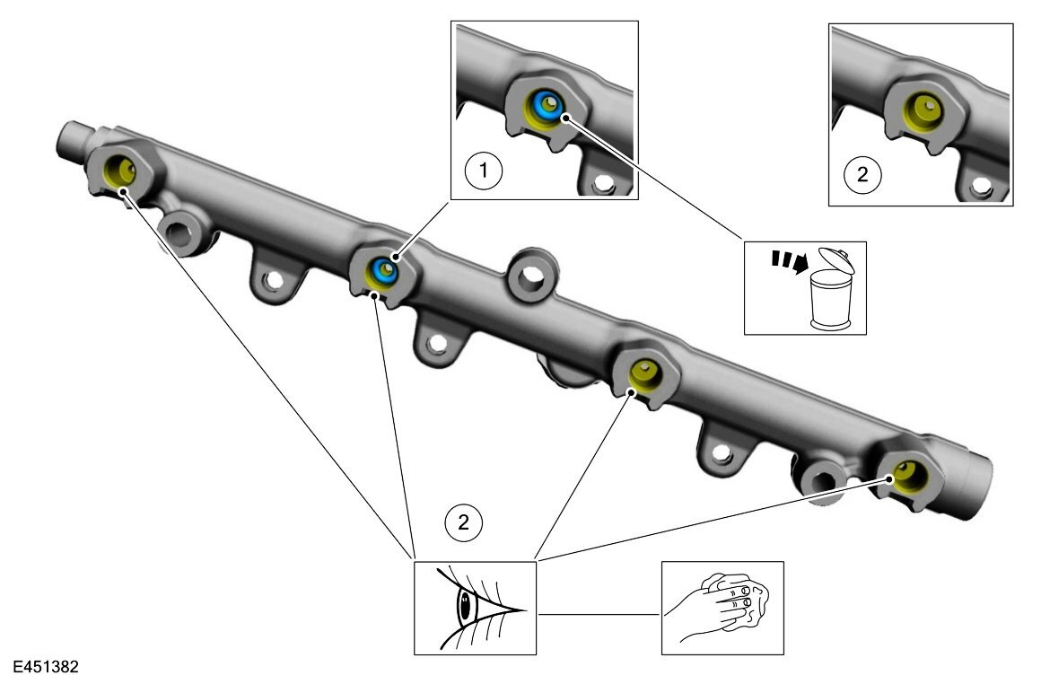
SSM 53443 2024-2025 Nautilus - Direct Injection Fuel Injector Removal Or Replacement 2024-2025 Nautilus vehicles require inspection and removal and discard of O-rings or debris that may be stuck in the direct injection fuel rail injector bores when removing or replacing the injectors for any reason. Workshop Manual (WSM), Section 303-04 Direct Fuel Injection Rail Removal and Installation has been updated to address this condition. The revised step from the referenced Workshop Manual removal and installation procedure... NOTICE: Check the fuel rail at fuel injector seating area for any sign of O-ring or its debris is present. Remove the O-ring and clean the injector bores. Inspect the fuel rail for any O-ring stuck in the injector bore. Remove O-ring. Clean the injector bores.

-
Welcome to the Forum @Shanejohn13! Attached below as PDF documents are Roof Opening Panel Front Trim removal & installation procedures for 2007-2014 Edge, 2015-2017 Edge, and 2018-2024 Edge... Good luck! Roof Opening Panel Trim — Front - Removal and Installation - 2007-2014 Edge Workshop Manual.pdf Roof Opening Panel Front Trim - Removal and Installation - 2015-2017 Edge Workshop Manual.pdf Roof Opening Panel Front Trim - Removal and Installation - 2018-2024 Edge Workshop Manual.pdf
-
Problem with camera heating
Haz replied to Iroga's topic in Glass, Lenses, Lighting, Mirrors, Sunroof (BAMR), Wipers
The following information applies to 2019-2024 Edges, and most of it is different from the previously posted 2015-2018 Edge documents. @Iroga: While you have indicated no Diagnostic Trouble Codes (DTCs) are present in the Image Processing Module A (IPMA), it may be useful for you to perform diagnostic Pinpoint Test C to assess the circuits and modules involved with the Camera Windshield Defrost Heater operation, especially noting this guidance... NOTE: Before replacing the camera windshield defrost heater, windshield or IPMA for a camera windshield defrost heater concern, verify the integrity of the wiring, connectors and terminals on the camera windshield defrost heater jumper harness. Lane Keeping Symptom Chart (partial) Diagostic Trouble Codes DTC B120C:11, DTC B120C:13 Refer to Wiring Diagram for schematic and connector information. Normal Operation and Fault Conditions The IPMA supplies voltage and ground to the camera windshield defrost heater. The IPMA uses input from the front camera and the ambient air temperature data from the PCM to command the heater on and off. The heater may be commanded on if the ambient temperature is below 5°C (41°F). Possible Causes Wiring, terminals or connectors Camera windshield defrost heater IPMA DTC Fault Trigger Conditions DTC Description Fault Trigger Conditions B120C:11 Heater for Windshield Mounted Sensor: Circuit Short To Ground An on-demand and continuous memory DTC that sets in the IPMA if an excessive current draw is detected on the heater output circuit. B120C:13 Heater for Windshield Mounted Sensor: Circuit Open An on-demand and continuous memory DTC that sets in the IPMA if a lower than expected current draw is detected on the heater output circuit. Visual Inspection and Diagnostic Pre-Checks Inspect the integrity of the wiring, terminals and connectors on the jumper harness between the vehicle harness and the camera windshield defrost heater. PINPOINT TEST C DTC (DIAGNOSTIC TROUBLE CODE) B120C:11, DTC (DIAGNOSTIC TROUBLE CODE) B120C:13 NOTICE: Use the correct probe adapter(s) when making measurements. Failure to use the correct probe adapter(s) may cause damage to the connector. Use only Rotunda Flex Probes (NUD105-R025D) NOTE: Before replacing the camera windshield defrost heater, windshield or IPMA for a camera windshield defrost heater concern, verify the integrity of the wiring, connectors and terminals on the camera windshield defrost heater jumper harness. C1 CHECK THE IPMA (IMAGE PROCESSING MODULE A) DIAGNOSTIC TROUBLE CODES (DTCS) Ignition ON. Using a diagnostic scan tool, perform the IPMA self-test. Is DTC B120C:11 or DTC B120C:13 present? Yes For DTC B120C:11, GO to C2 For DTC B120C:13, GO to C5 No The system is operating correctly at this time. INSPECT the connectors, wiring and the camera windshield defrost heater for damage or poor connections. C2 CHECK FOR SHORT TO GROUND WITH THE IPMA (IMAGE PROCESSING MODULE A) CAMERA HEATED WINDSHIELD ELEMENT DISCONNECTED Ignition OFF. Disconnect: Rain Sensor Module C914A. Ignition ON. Using a diagnostic scan tool, clear the IPMA Diagnostic Trouble Codes (DTCs). Perform the IPMA self-test. Is DTC B120C:11 present? Yes GO to C3 No INSTALL a new windshield. REFER to: Fixed Glass (501-11 Glass, Frames and Mechanisms, General Procedures). C3 CHECK THE IPMA (IMAGE PROCESSING MODULE A) CAMERA HEATED WINDSHIELD ELEMENT OUTPUT CIRCUIT FOR A SHORT TO GROUND Ignition OFF. Disconnect: IPMA C9224. Measure: Positive Lead Measurement / Action Negative Lead C9224 Pin 8 Ground Is the resistance greater than 10,000 ohms? Yes GO to C4 No REPAIR the circuit. After the repair, CLEAR the DTC , CYCLE the ignition, and RUN the IPMA on-demand self-test to re-enable the circuit. C4 CHECK IPMA (IMAGE PROCESSING MODULE A) CAMERA HEATED ELEMENT CIRCUITS FOR A SHORT TOGETHER Measure: Positive Lead Measurement / Action Negative Lead C9224 Pin 8 C9224 Pin 1 Is the resistance greater than 10,000 ohms? Yes GO to C5 No REPAIR the circuits. After the repair, CLEAR the DTC , CYCLE the ignition, and RUN the IPMA on demand self-test to re-enable the circuit. C5 CHECK FOR DTC (DIAGNOSTIC TROUBLE CODE) B120C:13 WITH THE IPMA (IMAGE PROCESSING MODULE A) CAMERA HEATED ELEMENT CIRCUITS JUMPERED TOGETHER Ignition OFF. Disconnect: Rain Sensor Module C914A. Connect: Lead 1 Measurement / Action Lead 2 C914A Pin 1 C914A Pin 3 Ignition ON. Using a diagnostic scan tool, clear the IPMA Diagnostic Trouble Codes (DTCs). Perform the IPMA self-test. Is DTC B120C:11 present? Yes REMOVE the fused jumper wire. INSTALL a new windshield. REFER to: Fixed Glass (501-11 Glass, Frames and Mechanisms, General Procedures). No REMOVE the fused jumper wire. GO to C6 C6 CHECK THE IPMA (IMAGE PROCESSING MODULE A) CAMERA HEATED WINDSHIELD ELEMENT CIRCUITS FOR AN OPEN Ignition OFF. Disconnect: IPMA C9224. Measure: Positive Lead Measurement / Action Negative Lead C9224 Pin 8 C914A Pin 3 C9224 Pin 1 C914A Pin 1 Are the resistances less than 3 ohms? Yes GO to C7 No REPAIR the affected circuit. C7 CHECK FOR CORRECT IPMA (IMAGE PROCESSING MODULE A) OPERATION Disconnect and inspect all IPMA connectors and related in-line connectors. Repair: corrosion (install new connector or terminals - clean module pins) damaged or bent pins - install new terminals/pins pushed-out pins - install new pins as necessary Reconnect the IPMA connectors and related in-line connectors. Make sure they seat and latch correctly. Operate the system to determine if the concern is still present. Is the concern still present? Yes CHECK OASIS for any applicable Technical Service Bulletins (TSBs). If a TSB exists for this concern, DISCONTINUE this test and FOLLOW the TSB instructions. If no Technical Service Bulletins (TSBs) address this concern, INSTALL a new IPMA REFER to: Image Processing Module A (IPMA) (419-07 Lane Keeping System, Removal and Installation). No The system is operating correctly at this time. The concern may have been caused by module connections. ADDRESS the root cause of any connector or pin issues. Related information is attached below as PDF documents... Good luck! IMAGE PROCESSING MODULE A (IPMA) - Removal and Installation - 2019 Edge Workshop Manual.pdf Interior Rear View Mirror - Removal and Installation - 2019 Edge Workshop Manual.pdf Rain Sensor - Removal and Installation - 2019 Edge Workshop Manual.pdf Body Control Module (BCM) - Fuse F36 (15 amp) Location Red-Box Highlighted - 2019 Edge.pdf RAIN SENSOR - Heater Pwr-Gnd Circuits Depicted In This Wiring Diagram - 2019 Edge.pdf RAIN SENSOR - Connector C914A Location - 2019 Edge.pdf RAIN SENSOR - Connector C914A Pinout - 2019 Edge.pdf IMAGE PROCESSING MODULE A (IPMA) - Heater Pwr-Gnd Supplied Via Rain Sensor Conector C914 Pins 1 & 3 - Wiring Diagram - 2019 Edge.pdf IMAGE PROCESSING MODULE A (IPMA) - Power Distribution Wiring Diagram - 2019 Edge.pdf Rain Sensor, IPMA, Heater - Ground Termination G304 Location - 2019 Edge.pdf Rain Sensor, IPMA, Heater - Ground Splices S912 & S913 Location - 2019 Edge.pdf IMAGE PROCESSING MODULE A (IPMA) - Ground Wiring Diagram - 2019 Edge.pdf IMAGE PROCESSING MODULE A (IPMA) - Connector C9224 Pinout - 2019 Edge.pdf IMAGE PROCESSING MODULE A (IPMA) - Connector C9224 Location - 2019 Edge.pdf
-HeaterPwr-GndSuppliedViaRainSensorConectorC914Pins13-WiringDiagram-2019Edge.thumb.jpg.0684fb3d51c7ec4fbeb834cb56b733e0.jpg)


-
Problem with camera heating
Haz replied to Iroga's topic in Glass, Lenses, Lighting, Mirrors, Sunroof (BAMR), Wipers
Welcome to the Forum @Iroga! Absent you mentioning your Edge's model year, I pulled the following 2015-2018 Edge documents to supplement @Wubster100's research... Good luck! Body Control Module (BCM) - Fuse F36 (15 amp) Location Red-Box Highlighted - 2015 Edge.pdf Lane Keeping System - Component Location - Description and Operation - 2015 Edge Workshop Manual.pdf Body Control Module (BCM) - Fuse F36 (15 amp) Power Distribution Wiring Diagram - 2015 Edge.pdf Interior Rear View Mirror - Removal and Installation - 2015 Edge Workshop Manual.pdf Image Processing Module A (IPMA) Camera Heated Windshield Element - Removal and Installation - 2015 Edge Workshop Manual.pdf Body Control Module (BCM) - Conector-Fuse-Relay Locations Illustration - 2015 Edge.pdf AUTO-DIMMING INTERIOR MIRROR - Connector C9012 Loction- 2015 Edge.pdf AUTO-DIMMING INTERIOR MIRROR - Connector C9012 - 2015 Edge.pdf CAMERA WINDSHIELD DEFROST HEATER - Connectors C9048A & C9048B Loction - 2015 Edge.pdf CAMERA WINDSHIELD DEFROST HEATER - Connector C9048A - 2015 Edge.pdf CAMERA WINDSHIELD DEFROST HEATER - Connector C9048B - 2015 Edge.pdf IPMA-Camera Windshield Defrost Heater - Wiring Diagram - 2015 Edge.pdf -
Windshield Replacement
Haz replied to 1004ron's topic in Glass, Lenses, Lighting, Mirrors, Sunroof (BAMR), Wipers
@Wubster100: Requested information is attached below as PDF documents... Good luck! Rain Sensor Module - Connector C914 Pinout - 2021 Edge.pdf Rain Sensor Module - Connector C914 Location - 2021 Edge.pdf Rain Sensor Module - Power Distribution Wiring Diagram - 2021 Edge.pdf Rain Sensor Module - Grounds Wiring Diagram - 2021 Edge.pdf Rain Sensor Module with Adaptive Cruise - Wiring Diagram - 2021 Edge.pdf IMAGE PROCESSING MODULE A (IPMA) - Connector C9224 Pinout - 2021 Edge.pdf Rain Sensor Module - Wiring Diagram - 2021 Edge.pdf Wipers and Washers - Rain Sensor Wiring Diagram 81-2 Extension - 2021 Edge.pdf Wipers and Washers - Rain Sensor Wiring Diagram 81-1 Extension - 2021 Edge.pdf -
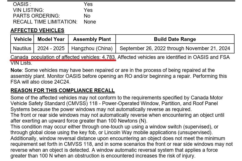
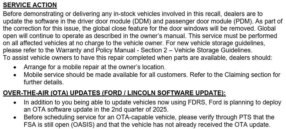
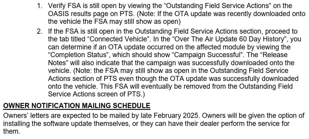
** The complete Canadian Dealer Bulletin and tentative Letter to Owners have been released. Technical Instructions are identical ** Tentative Letter To Owners


-
Good luck! 360 Camera - Wiring Diagram 2 - 2024 Edge - China.pdf 360 Camera - Wiring Diagram 1 - 2024 Edge - China.pdf Parking Aid - Component Location - Description and Operation - 2024 Edge Workshop Manual - China.pdf Side Parking Aid Camera - Removal and Installation - 2024 Edge Workshop Manual - China.pdf

-
Welcome to the Forum @RedMtDave! While their inventory status could be faulty, these online OEM Ford Parts sellers show a Right Hand and a Left Hand as being in stock and available to ship. Good luck!


-FillerPlugONLY.jpg.8e52205c0a74d7b50e2541c4a0ce3a00.jpg)


-HeaterPwr-GndSuppliedViaRainSensorConectorC914Pins13-WiringDiagram-2019Edge.jpg.c7278596d2902a1149baa5882aafdf68.jpg)