Haz
-
Posts
1,568 -
Joined
-
Last visited
-
Days Won
436
Content Type
Profiles
Forums
Gallery
Everything posted by Haz
-
See this post for part numbers and FordParts.com listings. Good luck!
-
Reply to above question posted here. Good luck!
- 1 reply
-
- 1
-

-
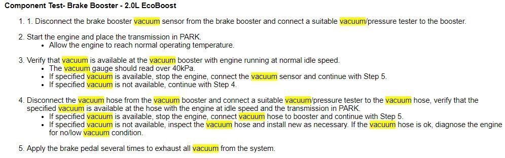
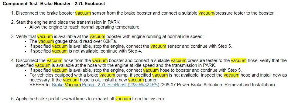
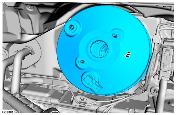
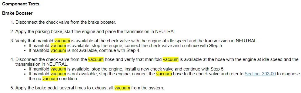
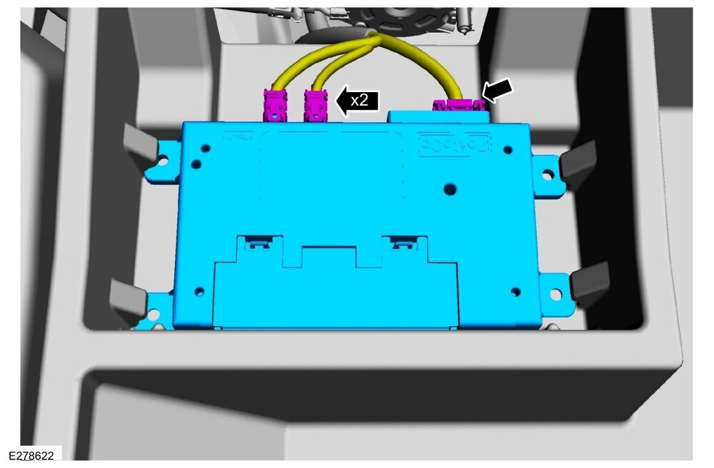
Replying to question about Brake Booster types installed on 2019-2024 Edge - Vacuum versus Electric. 2007 through 2024 Edge: Vacuum Brake Booster only, regardless of whether Cruise Control is conventional or adaptive. Brake Booster illustration from 2015-2024 Edge Workshop Manuals... Typical cross-generational Brake Booster component test descriptions... Per your 2020 Workshop Manual description, all Edge/MKX, and Nautilus (thru 2023) Adaptive Cruise Control systems utilize the ABS Module and Hydraulic Control Unit (HCU) to accomplish Adaptive Cruise braking. So, no, an Electric Brake Booster is not required for Adaptive Cruise Control on an Edge, MKX, or Nautilus (thru 2023). With that said, the 2024 Nautilus is equipped with an Electric Brake Booster which is utilized by its Adaptive Cruise Control system. From the 2024 Nautilus Workshop Manual... Placing your device cursor over underlined acronyms may yield a full-words description of the acronyms. Electric Brake Booster (EBB) Assembly The EBB is serviced as a single assembly and should NOT be disassembled. The EBB assembly contains the ABS module, solenoid valves, pressure sensor and hydraulic pump motor ( HCU ); the EBB also takes the place of the brake master cylinder and the vacuum booster. The ABS module is serviced as an assembly with the EBB . The ABS module is the ECU for the ABS and stability control systems. The module monitors all sensor inputs and all CAN messages relating to ABS and stability control, then directly controls the solenoid valves and the hydraulic pump motor in the EBB . When a new EBB assembly is installed, the ABS module must be programmed with the current vehicle configuration information. Electric Brake Booster (EBB) The cruise control deactivator switch is integrated in the EBB and opens when the brake pedal is applied and removes the ground signal from the PCM input circuit releasing the throttle and immediately deactivating the ACC system. Electric Brake Booster (EBB) - Isolated Component Illustration - 2024 Nautilus Workshop Manual Electric Brake Booster (EBB) - Installed Component View Showing Electrical Connectors - 2024 Nautilus Workshop Manual Electric Brake Booster (EBB) - Installed Component View Showing Brake Lines Attached - 2024 Nautilus Workshop Manual and... The ACC system has the capability for the driver to change from ACC to standard cruise control. The steering wheel switches are used to switch from the ACC system to standard cruise control system within the message center. For information on selecting the standard cruise control in the message center, refer to the Owner's Literature. Once the driver has selected the standard cruise control in the message center, the ACC indicator is replaced by the standard cruise control indicator. The vehicle no longer responds to lead vehicles or automatic braking. Upon the next ignition cycle, the vehicle defaults back to the ACC system. Good luck!
-IsolatedComponentIllustration-2024NautilusWorkshopManual.thumb.jpg.a309887f3d48ed43692bfa6808cdf277.jpg)
-InstalledComponentViewShowingElectricalConnectors-2024NautilusWorkshopManual.thumb.jpg.31a49f9e69fc9773bfdcc1731b992277.jpg)
-InstalledComponentViewShowingBrakeLinesAttached-2024NautilusWorkshopManual.thumb.jpg.314c96bca18fefe6a1e0cb87bc721dae.jpg)
-
Installing Sunvisor 2018 Edge
Haz replied to crazywater's topic in Interior, A.C., Heat, Interior Trim
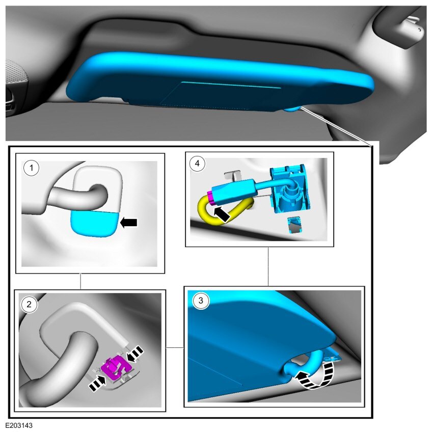
Welcome to the Forum, @Dougbobo! From the 2018 Edge Workshop Manual... Remove Sun Visor Remove the sun visor retainer cover. Remove the sun visor retainer. Remove the sun visor. If equipped. Disconnect the sun visor electrical connector. Good luck!
-
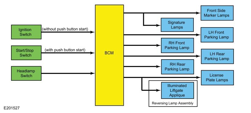
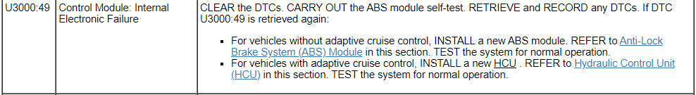
Attached below as PDF documents are Headlamp-related 2017 Edge Wiring diagrams, Connector details and Ground circuit termination locations , and an Exterior Lighting system description, which provides the following explanation... Placing your device cursor over underlined acronyms may yield a full-words popup description of those acronyms. Parking, Rear, and License Plate Lamps System Diagram Parking Lamps The BCM monitors the headlamp switch position by sending voltage signals on multiple circuits to the headlamp switch. There is one circuit for each headlamp switch position. At any given time, one of the signal circuits is switched to ground to indicate the headlamp switch position. If the BCM detects a fault from the headlamp switch or loses communication with the headlamp switch, the BCM turns the parking and headlamps on. This is normal behavior of the BCM when a fault has been detected with the inputs from the headlamp switch. When the BCM receives an input requesting the parking lamps on, it provides voltage to the parking lamps. The BCM also provides Field Effect Transistor (FET) protection of the parking lamps output circuits. When an excessive current draw is detected, the BCM disables the affected parking lamps circuit driver. Signature Lamps Each of the signature lamp assemblies consist of multiple Light Emitting Diodes (LEDs) that receive fused voltage when the ignition is in ON or START. When the signature lamps receive fused voltage from the BJB , and the parking lamps are OFF, the signature lamps illuminate at full intensity. When the parking lamps are activated and the BCM sends a second voltage to the signature lamps to indicate the parking lamps are activated, the signature lamps operate at a reduced intensity. Field Effect Transistor (FET) Protection The BCM utilizes an Field Effect Transistor (FET) protective circuit strategy for many of its outputs, for example, lamp output circuits. Output loads (current level) are monitored for excessive current (typically short circuits) and are shut down (turns off the voltage or ground provided by the module) when a fault event is detected. A Field Effect Transistor (FET) is a type of transistor that the control module software uses to control and monitor current flow on module outputs. The Field Effect Transistor (FET) protection strategy prevents module damage in the event of excessive current flow. Output loads (current level) are monitored for excessive current draw (typically short circuits). When a fault event is detected the Field Effect Transistor (FET) turns off and a short circuit DTC sets. The module resets the Field Effect Transistor (FET) protection and allows the circuit to function when the fault is corrected or the ignition state is cycled off and then back on. When the excessive circuit load occurs often enough, the module shuts down the output until a repair procedure is carried out. Each Field Effect Transistor (FET) protected circuit has 3 predefined levels of short circuit tolerance based on a module lifetime level of fault events based upon the durability of the Field Effect Transistor (FET). If the total tolerance level is determined to be 600 fault events, the 3 predefined levels would be 200, 400 and 600 fault events. When each level is reached, the DTC associated with the short circuit sets along with DTC U1000:00. These Diagnostic Trouble Codes (DTCs) can be cleared using the module on-demand self-test, then the Clear DTC operation on the scan tool (if the on-demand test shows the fault corrected). The module never resets the fault event counter to zero and continues to advance the fault event counter as short circuit fault events occur. If the number of short circuit fault events reach the third level, then Diagnostic Trouble Codes (DTCs) U1000:00 and U3000:49 set along with the associated short circuit DTC . DTC U3000:49 cannot be cleared and the module must be replaced after the repair. Please consider posting a photo or two of your Raptor-style grille, after its installation is complete. Good luck! Headlamp, Left Hand - Wiring Diagram - 2017 Edge.pdf Headlamp, Right Hand - Wiring Diagram - 2017 Edge.pdf Headlamp, Right Hand - Connector C1285 Pin-Circuit Details - 2017 Edge.pdf Headlamp, Left Hand - Connector C1284 Pin-Circuit Details - 2017 Edge.pdf Headlamp, Left Hand - G111 Ground Circuit Termination Location - 2017 Edge.pdf Headlamp, Right Hand - G114 Ground Circuit Termination Location - 2017 Edge.pdf Exterior Lighting - System Operation and Component Description - 2017 Edge Workshop Manual.pdf Daytime Signature Lamps - Wiring Diagram - 2017 Edge.pdf Daytime Signature Lamp, Left Hand - Connector C1750 Pin-Circuit Details - 2017 Edge.pdf Daytime Signature Lamp, Right Hand - Connector C1751 Pin-Circuit Details - 2017 Edge.pdf
-
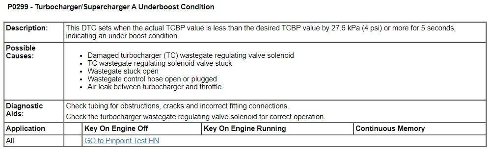
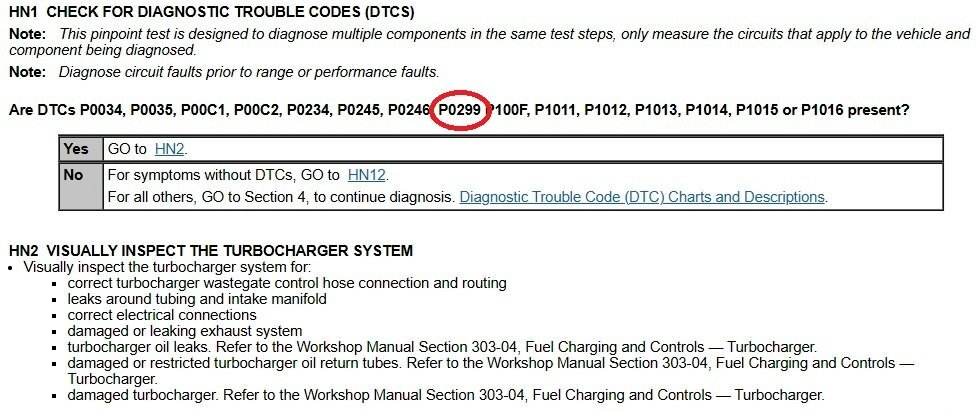
Welcome to the Forum, @Murtaza! The following description of Diagnostic Trouble Code (DTC) P0299 is from Ford's 2012 Gasoline Powertrain Control/Emissions Diagnosis (PC/ED) Manual... The following PDF file attachment is the above-mentioned diagnostic Pinpoint Test HN which evaluates for P0299 and other Turbocharger DTCs... 2012 Edge 2.0L EB DTC P0299 - Turbocharger Diagnostic Pinpoint Test HN - Ford PC-ED Manual.pdf And this excerpt from that document... While your mechanic may have already applied these diagnostic steps toward your 2012 Edge, you might discuss this document with your mechanic to deepen your confidence in your mechanic's advice. You may also want to read this past post: 2012 Troubleshooting P0299 (link to discussion) originated by Forum member @TxBucki. Good luck!
-
Remaining documents... Good luck! Inline Connector - Connector C139 Location - 2019 Edge.pdf Inline Connector - Connector C192 Location - 2019 Edge.pdf Inline Connector - Connector C193 Location - 2019 Edge.pdf Inline Connector - Connector C193 Pin-Circuit Details - 2019 Edge.pdf Inline Connector - Connector C192 Pin-Circuit Details - 2019 Edge.pdf Inline Connector - Connector C139 Pin-Circuit Details - 2019 Edge.pdf Inline Connector - Connector C134 Pin-Circuit Details - 2019 Edge.pdf Inline Connector - Connector C913 Pin-Circuit Details - 2019 Edge.pdf
-
Attached below and in an immediately following post are requested documents... Cruise Control Module (CCM) - Removal and Installation - 2019 Edge Workshop Manual.pdf Image Processing Module A (IPMA) - Removal and Installation - 2019 Edge Workshop Manual.pdf Image Processing Module A (IPMA) - Connector C9224 Location - 2019 Edge.pdf Image Processing Module A (IPMA) - Connector C9224 Pin-Circuit Details - 2019 Edge.pdf Image Processing Module A (IPMA) and Cruise Control Module (CCM) - Adaptive Cruise with Stop and Start - Wiring Diagram - 2019 Edge.pdf Image Processing Module A (IPMA) - Module Communications - Wiring Diagram - 2019 Edge.pdf Image Processing Module A (IPMA) - Power Distribution - Wiring Diagram - 2019 Edge.pdf Image Processing Module A (IPMA) - Grounds - Wiring Diagram - 2019 Edge.pdf Cruise Control Module (CCM) - Connector C1582 Location - 2019 Edge.pdf Cruise Control Module (CCM) - Connector C1582 Pin-Circuit Details - 2019 Edge.pdf Cruise Control Module (CCM) - Power Distribution - 2019 Edge.pdf Cruise Control Module (CCM) - Grounds - 2019 Edge.pdf Auto Stop and Start - Wiring Diagram - 2019 Edge.pdf Cruise Control Module (CCM) - Ground G111 Location - 2019 Edge.pdf Image Processing Module A (IPMA) - Ground G304 Location - 2019 Edge.pdf Inline Connector - Connector C913 Location - 2019 Edge.pdf Inline Connector - Connector C134 Location - 2019 Edge.pdf
-
Rear washer fluid not spraying
Haz replied to Rlahnan0121's topic in Glass, Lenses, Lighting, Mirrors, Sunroof (BAMR), Wipers
Additional related Workshop Manual PDF documents attached below... Good luck! Washer Hose Coupling - General Procedures - 2019 Edge Workshop Manual.pdf Washer Hose Repair - General Procedures - 2019 Edge Workshop Manual.pdf -
Link to recent Forum discussion on the hood flutter issue. Good luck!
-
Hood alignment procedure attached below... Good luck! Hood Alignment - General Procedures - 2024 Edge Workshop Manual.pdf
-
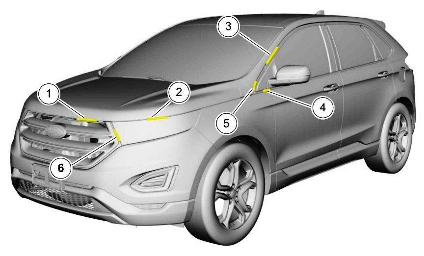
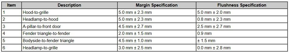
Welcome to the Forum, @GTEyes! Image to supplement @garycrist's comment... If adjusting the bump stop does not correct the excessive headlamp-to-hood margin, or, you just prefer to have your dealer perform the corrective work... The 2024 Edge Workshop Manual provides the following illustration and table of body component margin and flushness tolerances: Your dealer should be able to correct the condition, possibly by aligning the hood and/or adjusting the bumper cover and headlamp assembly to satisfy the above margin & flushness dimensional tolerances. Simply for your awareness of potential corrective process, the Hood Alignment procedure is attached below as a PDF document. Please note that due to PDF formatting, the action-step description at the bottom of all except the last page, applies to the illustration on the following page. Good luck!
-
From the 2019 Edge Workshop Manual... Good luck! Ignition Coil-On-Plug - Removal and Installation - 2.7L EcoBoost - 2019 Edge Workshop Manual.pdf Spark Plugs - Removal and Installation - 2.7L EcoBoost - 2019 Edge Workshop Manual.pdf Air Cleaner Outlet Pipe RH - Removal and Installation - 2.7L EcoBoost - 2019 Edge Workshop Manual.pdf
-
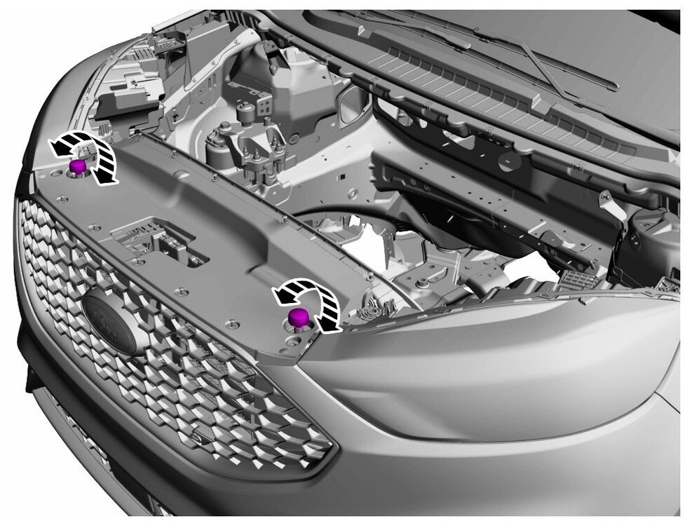
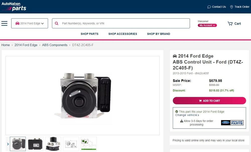
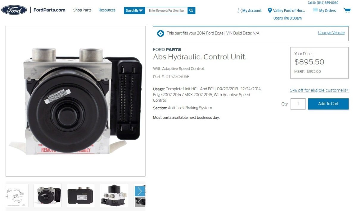
I regret that I cannot offer any clarity on the part differences between suffixes EB / DA /DB. Perhaps the part number your dealer was seeking is... Link to this ABS Control Unit - DT4Z-2C405-F - 2014 Ford Edge - FordParts online listing Link to this ABS Control Unit - DT4Z-2C405-F - 2014 Ford Edge - AutoNation Parts online listing Neither source explicitly indicates the part is on Backorder. Good luck!
-
Relevant wiring diagrams and electrical connector info, attached below as PDF documents... Good luck! Premium Audio without SYNC with Aux Audio Input Jack - Wiring Diagram - 2011 Edge.pdf Premium Audio without SYNC with Aux Audio Input Jack - Connector C3312 Location - 2011 Edge.pdf SYNC equipped, with Media Hub - Wiring Diagram - 2011 Edge.pdf Power Points - Wiring Diagram - 2011 Edge.pdf Premium Audio without SYNC with Aux Audio Input Jack - Connector C3312 Pin-Circuit Details - 2011 Edge.pdf
-
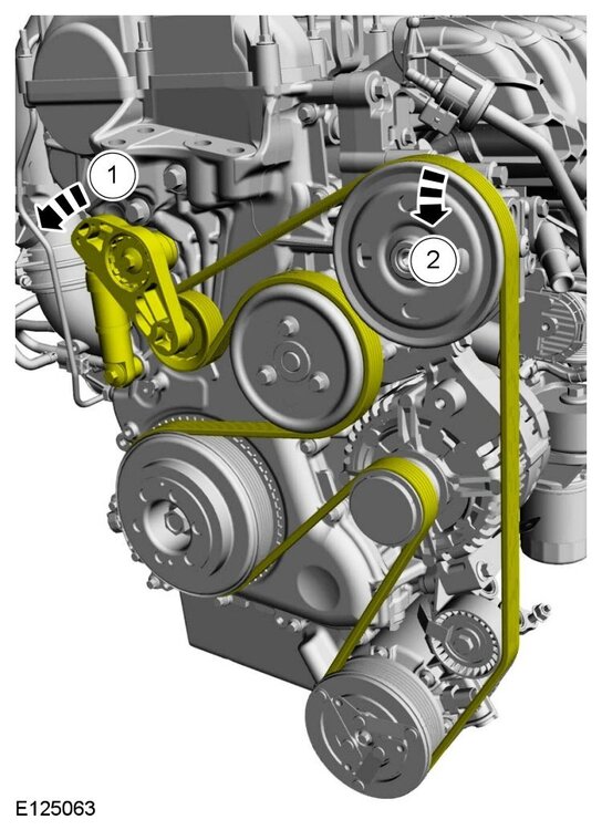
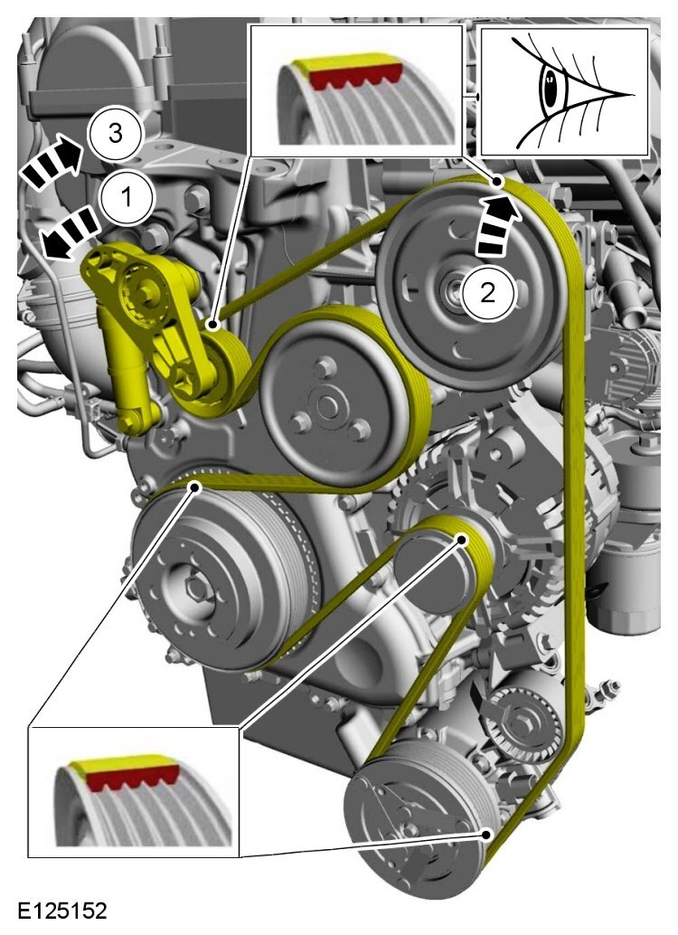
Welcome to the Forum, @Major! Attached at the bottom is the 2012 Edge Workshop Manual section you are seeking... Accessory Drive Belt - 2.0L EcoBoost - ENHANCED ILLUSTRATION, REMOVAL Accessory Drive Belt - 2.0L EcoBoost - ENHANCED ILLUSTRATION, INSTALLATION Good luck! Accessory Drive Belt - 2.0L EcoBoost - Removal and Installation - 2012 Edge workshop Manual.pdf

- 1 reply
-
- 2
-

-
Rear washer fluid not spraying
Haz replied to Rlahnan0121's topic in Glass, Lenses, Lighting, Mirrors, Sunroof (BAMR), Wipers
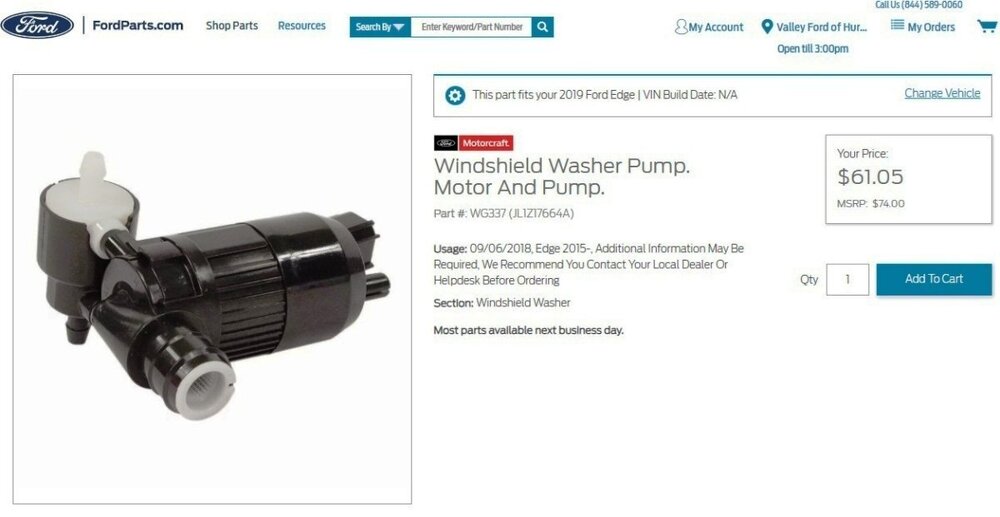
Welcome to the Forum, @Rlahnan0121! Relevant sections from the 2019 Edge Workshop Manual and Wiring resource are attached below as PDF documents... By reviewing the documents, you'll find that your Edge's single Washer Fluid Pump feeds both the Windshield washer jets and the Rear Glass washer jets by reversing its rotation to serve one set or the other set of washer jets, via a relay in the Windshield Wiper Motor and an unserviceable Rear Washer Relay in the Battery Junction Box (BJB). If you are capable with an electrical test light and Volt-Ohm Meter, it will be worthwhile for you -- or a professional technician -- to perform the diagnostic step-by-step of Pinpoint Test L toward determining the root cause of your Edge's rear washer performance issue. Good luck! Link to this page on Ford's online parts-selling site, FordParts.com Rear Washer Relay - Wiring Diagram - 2019 Edge.pdf Diagnostic Testing Procedure - Pinpoint Test L - THE REAR WINDOW WASHER IS INOPERATIVE - 2019 Edge.pdf Wipers and Washers - System Operation and Component Description - 2019 Edge Workshop Manual.pdf WINDSHIELD WASHER PUMP - Connector C137 Details - 2019 Edge.pdf WINDSHIELD WASHER PUMP - Connector C137 Location - 2019 Edge.pdf BATTERY JUNCTION BOX (BJB) - Connector C1035B Details - 2019 Edge.pdf BATTERY JUNCTION BOX (BJB) - Connector C1035B Location - 2019 Edge.pdf BATTERY JUNCTION BOX (BJB) - Illustration Showing F3, F28, Connector C1035B Locations - 2019 Edge.pdf BATTERY JUNCTION BOX (BJB) - Illustration Showing F3, F28, Connector C1035B Locations - 2019 Edge.pdf BATTERY JUNCTION BOX (BJB) - Fuse-Relay Listing (Partial) - 2019 Edge.pdf Windshield Washer Pump - Removal and Installation - 2019 Edge Workshop Manual.pdf Fender Splash Shield - Removal and Installation - 2019 Edge Workshop Manual.pdf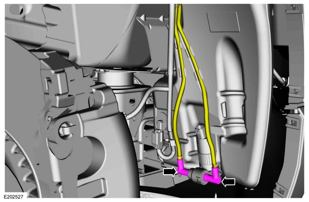
-
Reversing Lamps wiring diagram, connector details & locations, from 2020 Edge Wiring resource, attached below as PDF documents... Good luck! Reversing Lamps - Wiring Diagram - 2020 Edge.pdf Reversing Lamp - RH, Low Series Design - Connector C461 Location - 2020 Edge.pdf Reversing Lamp - LH, Low Series Design - Connector C451 Location - 2020 Edge.pdf Rear Lamp Assy with Reversing Lamp - RH, High Series Design - Connector C4484 Location - 2020 Edge.pdf Rear Lamp Assy with Reversing Lamp - LH, High Series Design - Connector C4483 Location - 2020 Edge.pdf Rear Lamp Assy with Reversing Lamp - LH, High Series Design - Connector C4483 Details - 2020 Edge.pdf Rear Lamp Assy with Reversing Lamp - RH, High Series Design - Connector C4484 Details - 2020 Edge.pdf Reversing Lamp - LH, Low Series Design - Connector C451 Details - 2020 Edge.pdf Reversing Lamp - RH, Low Series Design - Connector C461 Details - 2020 Edge.pdf Rear Lamps - Wiring Diagram - 2020 Edge.pdf
-
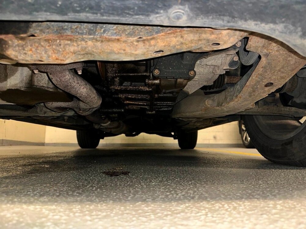
Welcome to the Forum, @Cmd511! Reposting your photo for improved viewability... From the 2008 Edge Workshop Manual... Engine Oil Leaks NOTE: When diagnosing engine oil leaks, the source of the leak must be positively identified prior to repair. If the vehicle is driven extensively between adding the fluorescent additive and performing the leak test, fan air or wind can spread the leaking oil and make identifying the location of the leak difficult. Prior to carrying out this procedure, clean the cylinder block, cylinder heads, valve covers, oil pan and flywheel with a suitable solvent to remove all traces of oil. Engine Oil Leaks — Fluorescent Oil Additive Method Use the 12 Volt Master UV Diagnostic Inspection Kit to carry out the following procedure for oil leak diagnosis. Add 29.6 ml (1 oz) of gasoline engine oil dye to a minimum of 0.47L (1/2 qt) and a maximum of 0.95L (1 qt) engine oil and fill through the engine oil fill. Thoroughly premix the gasoline engine oil dye or it will not have enough time to reach the crankcase, oil galleries and seal surfaces during this particular 15 minute test. The additive must be mixed well with oil and added through the oil fill. Check the level on the oil level indicator to determine what amount of oil to premix. If it is in the middle of the crosshatch area or below the full mark, use 0.95L (1 qt). If it is at the full mark, use 0.47L (1/2 qt). Run the engine for 15 minutes. Stop the engine and inspect all seal and gasket areas for leaks using the 12 Volt Master UV Diagnostic Inspection Kit. A clear bright yellow or orange area will identify the leak. For extremely small leaks, several hours may be required for the leak to appear. At the end of test, make sure the oil level is within the upper and lower oil indicator marks. Remove oil as necessary if it registers above the full mark. Leakage Points — Underhood Examine the following areas for oil leakage: Valve cover gaskets Cylinder head gaskets Oil cooler, if equipped Oil filter adapter Engine front cover Oil filter adapter and filter body Oil level indicator tube connection Engine Oil Pressure (EOP) switch Leakage Points — Under Engine, With Vehicle on Hoist Examine the following areas for oil leakage: Oil pan gaskets Oil pan sealer Engine front cover gasket Crankshaft front seal Crankshaft rear oil seal Oil filter adapter and filter body Oil cooler, if equipped Leakage Points — With Transmission and Flywheel Removed Examine the following areas for oil leakage: Crankshaft rear oil seal Rear main bearing cap parting line Flexplate mounting bolt holes (with flexplate installed) Pipe plugs at the end of oil passages Oil leaks at crimped seams in sheet metal parts and cracks in cast or stamped parts can be detected when using the dye method. Good luck!
- 1 reply
-
- 2
-
-
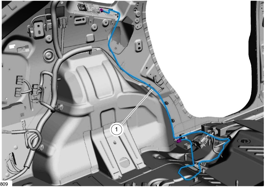
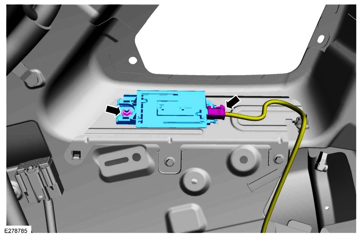
From the 2020 Edge Workshop Manual... Telematics Control Unit (TCU) Module The TCU connects the vehicle to a cellular network. It contains a non-serviceable internal SIM card. The TCU requires PMI when it is replaced. TCU Antenna The TCU antenna is used is used to boost reception for incoming and outgoing cellular network data. It is a compact, cellular phone type, planar inverted-F antenna. TCU Antenna Cable Routing Good luck!


-
The Workshop Manual is not explicit, but the 2015 Edge Wiring resource may be helpful... According to the following Component Location diagrams that depict four (4) Heated Oxygen Sensor (HO2S) and their red-lettered electrical Connector designations, Bank 1 is located on the backside of the engine and Bank 2 is located on the front side of the engine. Take note of the lower right corner red-circled arrow, which signals direction to Front of vehicle... Universal Heated Oxygen Sensor (HO2S) #11 - Connector C171 Location - 2.7L EcoBoost - 2015 Edge Heated Oxygen Sensor (HO2S) #12 - Connector C1570 Location - 2.7L EcoBoost - 2015 Edge Universal Heated Oxygen Sensor (HO2S) #21 - Connector C172 Location - 2.7L EcoBoost - 2015 Edge Heated Oxygen Sensor (HO2S) #22 - Connector C1569 Location - 2.7L EcoBoost - 2015 Edge The diagrams aren't explicit, as to HO2S designations, but I think, provide us a roadmap to the answer by looking to blue-circled listing in this portion of the last diagram above... ...where the example Bank & Sensor designation is expressed in the parentheses as CMP22. Extending that designation model to your question: Bank 1 Sensor 2 is Universal Heated Oxygen Sensor (HO2S) #21. While it's unclear what diagnostic method(s) and diagnostic tool(s) you've employed to target this specific Sensor, perhaps disconnecting its Connector C172 while monitoring whatever it is you're using, may verify this hopeful identification. Or you might disconnect another of the HO2S connectors with similar monitoring for comparable verification. Relevant Wiring Reference selections are attached below as PDF documents... The Ford Powertrain Control/Emissions Diagnosis Manual provides the following useful component & monitoring system descriptions... Universal Heated Oxygen Sensor (HO2S) The universal HO2S, sometimes referred to as a wideband oxygen sensor, uses the typical HO2S combined with a current controller in the PCM to infer an air to fuel ratio relative to the stoichiometric air to fuel ratio. This is accomplished by balancing the amount of oxygen ions pumped in or out of a measurement chamber within the sensor. The typical HO2S within the universal HO2S detects the oxygen content of the exhaust gas in the measurement chamber. The oxygen content inside the measurement chamber is maintained at the stoichiometric air to fuel ratio by pumping oxygen ions in and out of the measurement chamber. As the exhaust gasses get richer or leaner, the amount of oxygen that must be pumped in or out to maintain a stoichiometric air to fuel ratio in the measurement chamber varies in proportion to the air to fuel ratio. The amount of current required to pump the oxygen ions in or out of the measurement chamber is used to measure the air to fuel ratio. The measured air to fuel ratio is actually the output from the current controller in the PCM and not a signal that comes directly from the sensor. The universal HO2S also uses a self contained reference chamber to make sure an oxygen differential is always present. The oxygen for the reference chamber is supplied by pumping small amounts of oxygen ions from the measurement chamber into the reference chamber. The universal HO2S does not need access to outside air. Part to part variance is compensated for by placing a resistor in the connector. This resistor trims the current measured by the current controller in the PCM. The universal HO2S heater is embedded with the sensing element allowing the engine to enter closed loop operation sooner. The heating element heats the sensor to a temperature of 780°C to 830°C (1,436°F to 1,526°F). The VPWR circuit supplies voltage to the heater. The PCM controls the heater ON and OFF by providing the ground to maintain the sensor at the correct temperature for maximum accuracy. Heated Oxygen Sensor (HO2S) The HO2S detects the presence of oxygen in the exhaust and produces a variable voltage according to the amount of oxygen detected. A high concentration of oxygen (lean air to fuel ratio) in the exhaust produces a voltage signal less than 0.4 volt. A low concentration of oxygen (rich air to fuel ratio) produces a voltage signal greater than 0.6 volt. The HO2S provides feedback to the PCM indicating air to fuel ratio in order to achieve a near stoichiometric air to fuel ratio of 14.7:1 during closed loop engine operation. When the oxygen sensor is cold, disconnected or on initial start up, the voltage may read between 1.5 to 1.7 volts. The oxygen sensor voltage will decrease to the normal operating range of 0.0 to 1.1 volts during warm, stabilized engine running conditions. The HO2S heater is embedded with the sensing element. The heating element heats the sensor to a temperature of 800°C (1,472°F). At approximately 300°C (572°F) the engine enters closed loop operation. The VPWR circuit supplies voltage to the heater. The PCM turns the heater ON by providing the ground when the correct conditions occur. The heater allows the engine to enter closed loop operation sooner. The use of this heater requires the HO2S heater control to be duty cycled, to prevent damage to the heater. Heated Oxygen Sensor (HO2S) Monitor The HO2S monitor is an on board strategy designed to monitor the heated oxygen sensors for concerns or deterioration which can affect emissions. The fuel control or stream 1 HO2S are checked for correct output voltage and response rate. Response rate is the time it takes to switch from lean to rich or rich to lean. The rear or stream 2 HO2S is monitored for correct output voltage and is used for catalyst monitoring and fore aft oxygen sensor (FAOS) control. Input is required from the camshaft position (CMP) sensor, the crankshaft position (CKP) sensor, the engine coolant temperature (ECT) sensor or the cylinder head temperature (CHT) sensor (if equipped), the fuel rail pressure temperature (FRPT) sensor, the fuel tank pressure (FTP) sensor, the intake air temperature (IAT) sensor, the mass airflow (MAF) sensor (if equipped), the manifold absolute pressure (MAP) sensor, the throttle position (TP) sensor and vehicle speed to activate the HO2S monitor. The fuel system monitor and misfire detection monitor must also have completed successfully before the HO2S monitor is enabled. The HO2S senses the oxygen content in the exhaust flow. The typical HO2S outputs a voltage between 0 and 1.0 volt. Lean of stoichiometric, air to fuel ratio of approximately 14.7:1, the HO2S generates a voltage between 0 and 0.45 volt. Rich of stoichiometric, the HO2S generates a voltage between 0.45 and 1.0 volt. The current required to maintain the universal HO2S at 0.45 volt is used by the PCM to calculate the air to fuel ratio. The HO2S monitor evaluates the HO2S for correct function. The time between HO2S switches is monitored after vehicle startup and during closed loop fuel conditions. Excessive time between switches or no switches since startup indicates a concern. Since lack of switching concerns can be caused by HO2S concerns or by shifts in the fuel system, DTCs are stored that provide additional information for the lack of switching concern. Different DTCs indicate whether the sensor always indicates lean, rich, or disconnected. The HO2S signal is also monitored for high voltage, in excess of 1.1 volts. An over voltage condition is caused by a HO2S heater or battery power short to the HO2S signal line. A functional test of the rear HO2S is done during normal vehicle operation. The peak rich and lean voltages are continuously monitored. Voltages that exceed the calibrated rich and lean thresholds indicate a functional sensor. If the voltages have not exceeded the thresholds after a long period of vehicle operation, the air to fuel ratio may be forced rich or lean in an attempt to get the rear sensor to switch. This situation normally occurs only with a green, less than 804.7 km (500 miles), catalyst. If the sensor does not exceed the rich and lean peak thresholds, a concern is indicated. Also, a deceleration fuel shut off rear HO2S response test is done during a deceleration fuel shut off (DFSO) event. Carrying out the HO2S response test during a DFSO event helps to isolate a sensor concern from a catalyst concern. The response test monitors how quickly the sensor switches from a rich to lean voltage. It also monitors if there is a delay in the response to the rich or lean condition. If the sensor responds very slowly to the rich to lean voltage switch or is never greater than a rich voltage threshold or less than a lean voltage threshold, a concern is indicated. The malfunction indicator lamp (MIL) is activated after a concern is detected on 2 consecutive drive cycles. Good luck! Heated Oxygen Sensor (HO2S) #12 - Connector C1570 Circuit-Pin Details - 2.7L EcoBoost - 2015 Edge.pdf Heated Oxygen Sensor (HO2S) #22 - Connector C1569 Circuit-Pin Details - 2.7L EcoBoost - 2015 Edge.pdf Heated Oxygen Sensors (HO2S) #11, #12, #21, #22 -Wiring Diagram - 2.7L EcoBoost - 2015 Edge.pdf Universal Heated Oxygen Sensor (HO2S) #11 - Connector C171 Circuit-Pin Details - 2.7L EcoBoost - 2015 Edge.pdf Universal Heated Oxygen Sensor (HO2S) #21 - Connector C172 Circuit-Pin Details - 2.7L EcoBoost - 2015 Edge.pdf
11-ConnectorC171Location-2.7LEcoBoost-2015Edge.thumb.jpg.c9f477eada1db1213d6bd26fafefdf91.jpg)
21-ConnectorC172Location-2.7LEcoBoost-2015Edge.thumb.jpg.1d660047029a68bf865e966248f4b32a.jpg)
22-ConnectorC1569Location-2.7LEcoBoost-2015Edge.thumb.jpg.3f74a87059463b4840e4fe5a94525c7a.jpg)
12-ConnectorC1570Location-2.7LEcoBoost-2015Edge.thumb.jpg.eeffe13c4548ab89e52d1f6b20c2ae57.jpg)
22-INTERPRETATIONMODELILLUSTRATION.jpg.dd67ea42a589e65160b38ea4182e9973.jpg)
-
One additional... Front Bumper Cover - Removal and Installation - 2015 Edge Workshop Manual.pdf
-
Welcome to the Forum, @cota86! Relevant 2015 Edge 2.7L EcoBoost Workshop Manual sections attached below as PDF documents... Good luck! Heated Oxygen Sensor (HO2S) - Removal and Installation - 2.7L EcoBoost - 2015 Edge Workshop Manual.pdf Air Cleaner Outlet Pipe RH - Removal and Installation - 2.7L EcoBoost - 2015 Edge Workshop Manual.pdf Charge Air Cooler (CAC) Intake Pipe - Removal and Installation - 2.7L EcoBoost - 2015 Edge Workshop Manual.pdf Air Cleaner - Removal and Installation - 2.7L EcoBoost - 2015 Edge Workshop Manual.pdf Charge Air Cooler (CAC) - Removal and Installation - 2.7L EcoBoost - 2015 Edge Workshop Manual.pdf 303-476 - Socket, Exhaust Gas Oxygen Sensor - Rotunda Special Tool.pdf
-
Welcome to the Forum, @tuxnet! From the 2014 Edge Workshop Manual... As indicated above, if your Edge is not equipped with Adaptive Cruise, then you may replace only the ABS Module. However, if your Edge is equipped with Adaptive Cruise, then the ABS/HCU is serviced as one unit. Replacing the ABS Module will require your Edge's As-Built ABS Module data to be programmed into the new replacement ABS Module. Due to the indicated internal failure of the ABS Module , you will likely be unable to access that data in your Edge's current ABS Module. Click on this link to the Ford Service site, select Country/Language pick list values, then enter your Edge's VIN and the Security Check value. ABS Module As-Built values are contained in the Line 760 address entries of your VIN query results... Relevant Workshop Manual sections are attached below as PDF documents... Good luck! Anti-Lock Brake System (ABS) Module - Removal and Installation - 2014 Edge Workshop Manual.pdf Hydraulic Control Unit (HCU) - Removal and Installation - 2014 Edge Workshop Manual.pdf Hydraulic Control Unit (HCU) - Enhanced Illustration - 2014 Edge Workshop Manual.pdf Anti-Lock Brake System (ABS) Module - Enhanced Illustration - 2014 Edge Workshop Manual.pdf Intake Air System Components — Exploded View - Removal and Installation - 2014 Edge Workshop Manual.pdf Quick Connect Coupling - General Procedures - 2014 Edge Workshop Manual.pdf Battery and Battery Tray — Exploded View - Removal and Installation - 2014 Edge Workshop Manual.pdf Battery and Battery Tray — Exploded View - Enhanced Image - 2014 Edge Workshop Manual.pdf Brake System Bleeding - General Procedures - 2014 Edge Workshop Manual.pdf

-
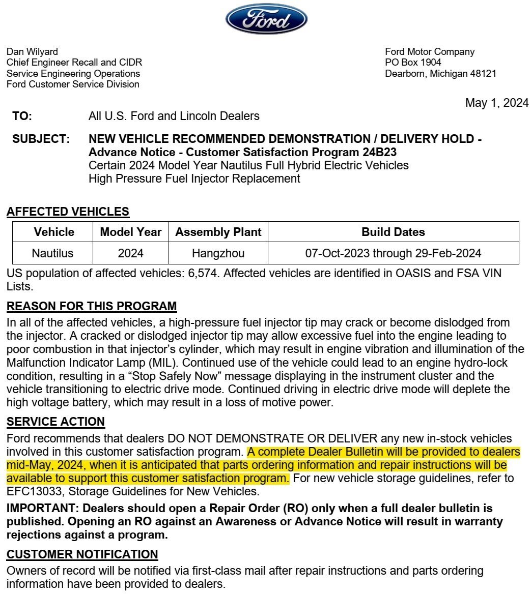
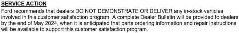
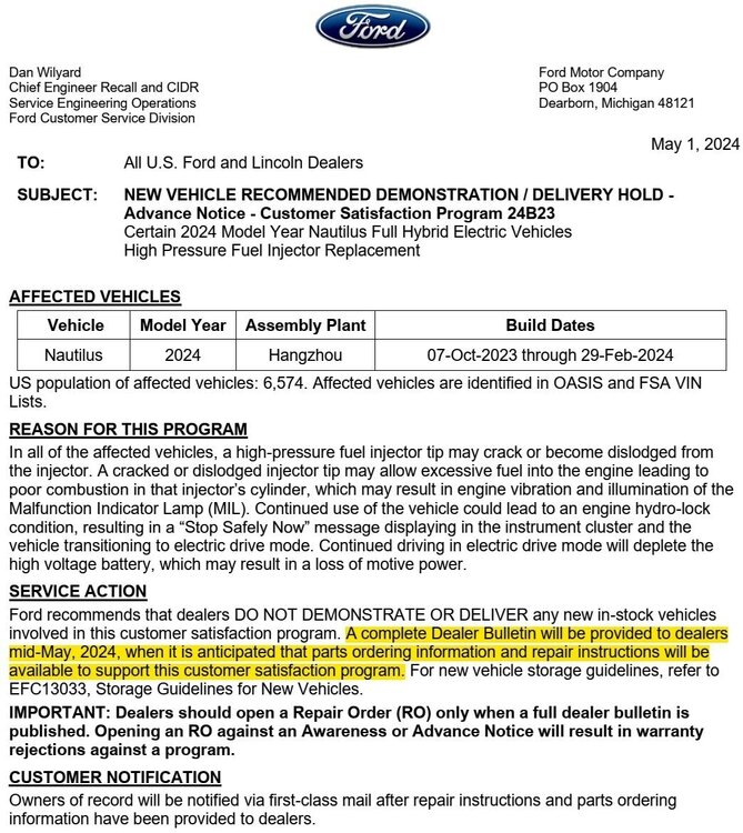
@markfm has rightfully observed that the Ford of Canada Advance Notice states the Full Dealer Notice is expected by the end of May 2024, which I overlooked in my haste to post that communication... A Version 2 of the U.S. Advance Notice letter has now been issued, showing Mid-May 2024 for issuance of the Complete Dealer Bulletin... Good luck!
-IsolatedComponentIllustration-2024NautilusWorkshopManual.jpg.d16925790bb1c31f6b62fde8355e996b.jpg)
-InstalledComponentViewShowingElectricalConnectors-2024NautilusWorkshopManual.jpg.ad6958549e9bf497f25cda81c723dce4.jpg)
-InstalledComponentViewShowingBrakeLinesAttached-2024NautilusWorkshopManual.jpg.16f607902fc4fc10e4c16519e91a544b.jpg)


11-ConnectorC171Location-2.7LEcoBoost-2015Edge.jpg.b5781af332bb13a02626c25ea8e08233.jpg)
21-ConnectorC172Location-2.7LEcoBoost-2015Edge.jpg.0f94f15d1f2bbcb66abcb2c97d3570ad.jpg)
22-ConnectorC1569Location-2.7LEcoBoost-2015Edge.jpg.d317a86357ad5dfbda460d62d0f067cd.jpg)
12-ConnectorC1570Location-2.7LEcoBoost-2015Edge.jpg.00bae9c8f52bcef270a762f7f3e775da.jpg)