Haz
-
Posts
1,568 -
Joined
-
Last visited
-
Days Won
439
Content Type
Profiles
Forums
Gallery
Everything posted by Haz
-
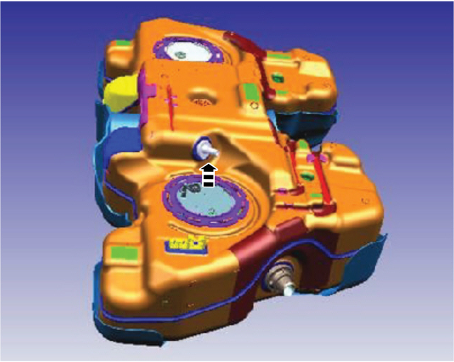
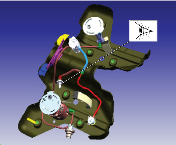
TECHNICAL SERVICE BULLETIN 2.0L - AWD - Various Driveability Symptoms And/Or Illuminated MIL With Evaporative Emissions DTCs After A Refuel Event 24-2199 01 July 2024 Model: Ford 2024 Edge Engine: 2.0L EcoBoost AWD Markets: North American markets only Issue: Some 2024 Edge vehicles equipped with a 2.0L engine and AWD may experience the fuel tank not filling up beyond half-full, hard to start, and/or stalls upon restart after refueling. A MIL with DTC P04F0, P0451, P0455, and/or P0496 may also be stored in the PCM. This may be due to a disconnected fuel vapor line inside the fuel tank. To correct the condition, follow the Service Procedure to reattach the fuel tank vapor line inside the fuel tank. Action: Follow the Service Procedure to correct the condition on vehicles that meet all of the following criteria: • 2024 Edge • 2.0L • AWD • At least one of the following symptoms: - Fuel tank not filling up beyond half-full - Hard to start - Stalls upon restart after refueling Parts Service Part Number Claim Quantity Package Order Quantity Number in Package Description W714265-S442 2 1 4 Exhaust Nut CV6Z-9450-E 1 1 1 Exhaust Gasket F2GZ-4682-A 3 3 1 Driveshaft To PTU Bolts/Straps W790063-S900 3 1 3 Driveshaft To Pinion Bolts/Straps W712154-S439 2 1 4 Center Bearing Bolts 4L3Z-9276-AA 1 1 1 Fuel Pump And Sender Unit Ring CCPZ-3B477-B 2 2 1 Axle Nut K2GZ-9D653-A 1 1 1 Evaporative Emissions Canister W718188-S439 8 2 4 Wheel Bearing And Hub Retainers W715448-S439 2 1 4 Halfshaft Retaining Clip W715624-S439 4 1 4 Caliper Bracket Support Bolt XY-75W-QL As Needed As Needed Motorcraft® Differential Rear Drive Unit Fluid PM-4-A As Needed As Needed Motorcraft® Metal Brake Parts Cleaner (Compliant With Low Volatile Organic Compound Requirements As Required In Some USA States) PM-4-B As Needed As Needed Motorcraft® Metal Brake Parts Cleaner (Not Compliant With Volatile Organic Compound Requirements) Claim Quantity refers to the total number of individual pieces required to repair the vehicle. Package Order Quantity refers to the amount of the service part number package(s) required to repair the vehicle. Number In Package refers to the number of individual pieces included in a service part number package. As Needed indicates the part is necessary but amount of the part may vary and/or is not a whole number. Parts can be billed out as non-whole numbers, including less than 1. Warranty Status: Eligible under provisions of New Vehicle Limited Warranty (NVLW)/Emissions Warranty/Service Part Warranty (SPW)/Service Part New Vehicle (SPNV)/Extended Service Plan (ESP) coverage. Limits/policies/prior approvals are not altered by a TSB. NVLW/Emissions Warranty/SPW/SPNV/ESP coverage limits are determined by the identified causal part and verified using the OASIS part coverage tool. Labor Times Description Operation No. Time 2024 Edge AWD 2.0L EcoBoost: Inspect And Connect Vapor Hose Includes Time To Replace EVAP Canister And Remove And Install Fuel Pump Sender (Do Not Use With Any Other Labor Operations) 242199A 4.9 Hrs. Repair/Claim Coding Causal Part: 9002 Condition Code: 01 Service Procedure 1. Remove the fuel tank assembly. Refer to the WSM, Section 310-01A, Removal and Installation, Fuel Tank. 2. Remove fuel pump and sender unit. Refer to the WSM, Section 310-10A, Removal and Installation, Fuel Pump and Sender. 3. Inspect the inside of the fuel tank for a disconnected fuel vapor hose. (Figures 1-2) Figure 1 Figure 2 4. Is the hose disconnected? (1). Yes - reattach the hose. Proceed to Step 5. NOTE: Do not reinstall the fuel tank until the EVAP canister has been replaced. (2). No - reassemble vehicle and refer to the WSM for normal diagnostics outside of this article. Repair is complete. 5. Replace the EVAP canister. Refer to WSM, Section 303-13A, Removal and Installation, Evaporative Emission Canister. © 2024 Ford Motor Company All rights reserved. NOTE: The information in Technical Service Bulletins is intended for use by trained, professional technicians with the knowledge, tools, and equipment to do the job properly and safely. It informs these technicians of conditions that may occur on some vehicles, or provides information that could assist in proper vehicle service. The procedures should not be performed by "do-it-yourselfers". Do not assume that a condition described affects your car or truck. Contact a Ford or Lincoln dealership to determine whether the Bulletin applies to your vehicle. Warranty Policy and Extended Service Plan documentation determine Warranty and/or Extended Service Plan coverage unless stated otherwise in the TSB article. The information in this Technical Service Bulletin (TSB) was current at the time of printing. Ford Motor Company reserves the right to supersede this information with updates. The most recent information is available through Ford Motor Company's on-line technical resources. TSB 24-2199 and referred-to Workshop Manual sections are attached below as PDF documents... TSB 24-2199 - 2.0L EcoBoost - AWD - Various Driveability Symptoms And-Or Illuminated MIL With Evap Emissions DTCs After A Refuel Event.pdf Fuel Tank - Removal and Installation - 2022-2024 Edge Workshop Manual.pdf Fuel Pump and Sender Unit - Removal and Installation - 2022-2024 Edge Workshop Manual.pdf Evaporative Emission Canister - Removal and Installation - 2022-2024 Edge Workshop Manual.pdf
-
Welcome to the Forum, @Terrible Tim! Relevant sections from the 2011 Edge Workshop Manual and Wiring Resource are attached below as PDF documents... If your diagnostic efforts progress to you requiring electrical connector information, I can supply that as well. Good luck! Front Park-Turn Lamps - Wiring Diagram - 2011 Edge.pdf Park-Turn Lamps, Left Hand - Fuse F14 - Wiring Diagram - 2011 Edge.pdf Park-Turn Lamps, Right Hand - Fuse F13 - Wiring Diagram - 2011 Edge.pdf Body Control Module (BCM) - Fuse Location Diagram - 2011 Edge.pdf Body Control Module (BCM) - Fuse-Circuits Listing - 2011 Edge.pdf Turn Signal and Hazard Lamps - Diagnosis and Testing - 2011 Edge.pdf Parking, Rear and License Plate Lamps - Diagnosis and Testing - 2011 Edge.pdf HID Headlamps - Wiring Diagram - 2011 Edge.pdf Adaptive Headlamps - Wiring Diagram - 2011 Edge.pdf Headlamps - Diagnosis and Testing - 2011 Edge.pdf
- 1 reply
-
- 1
-

-
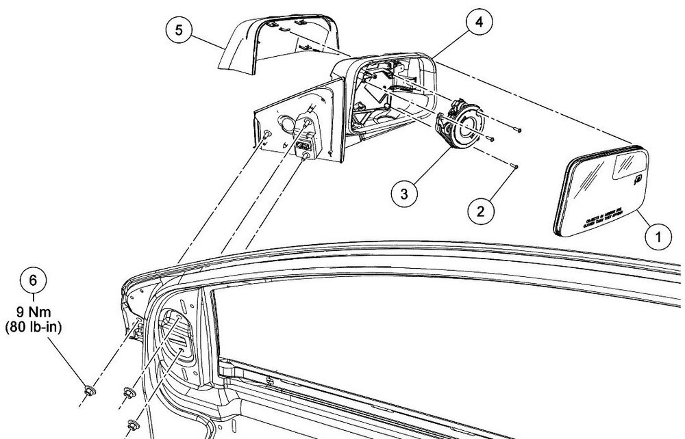
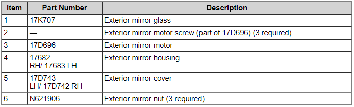
Should the need arise, 2014 Edge Workshop Manual procedures to disassemble and/or remove exterior mirror from vehicle are attached below as a PDF documents... Good luck! Exterior Mirror - Removal and Installation - 2014 Edge Workshop Manual.pdf Exterior Mirror Cover - Removal and Installation - 2014 Edge Workshop Manual.pdf Exterior Mirror Glass - Removal and Installation - 2014 Edge Workshop Manual.pdf Exterior Mirror Motor - Removal and Installation - 2014 Edge Workshop Manual.pdf
-
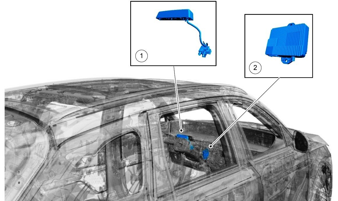
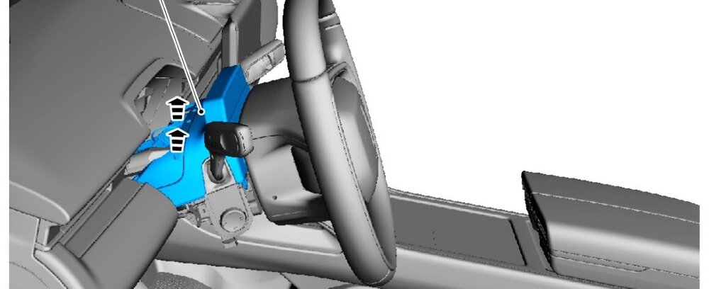
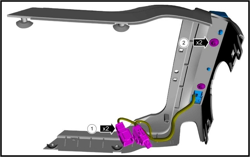
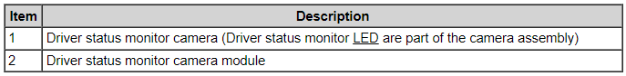
SSM 52680 2024 Nautilus - Driver Status Monitor Camera Off-Center The driver status monitor camera in some 2024 Nautilus vehicles may be positioned off-center on the top of the steering column shroud. The steering column and shrouds normally rotate back and forth due to its tilt and telescopic feature. Assure any customers who report this concern that it does not affect Blue Cruise function. If this condition occurs, do not manually twist the driver status monitor camera to center it. Telescoping the steering column out all the way out and then all the way in should center the driver status monitor camera with no repairs needed. The steering column position can then be set to the customer's preference. Supplement illustrations from 2024 Nautilus Workshop Manual... Interior Camera System - Component Locations

- 1 reply
-
- 2
-
-
From the 2020 Edge Owner's Manual, United Kingdom (UK) version... Lighting - Glare-Free High Beam (If Equipped) GLARE-FREE HIGH BEAM (IF EQUIPPED) WARNING: The system does not relieve you of your responsibility to drive with due care and attention. You may need to override the system if it does not turn the high beams on or off. WARNING: You may need to override the system when approaching other road users. WARNING: You may need to override the system during inclement weather. WARNING: Do not use the system in poor visibility, for example fog, heavy rain, spray or snow. WARNING: The system may not adapt the high beams to avoid glare if the lights of oncoming vehicles are hidden by obstacles, for example guard rails. WARNING: Inspect and replace the windshield wiper blades regularly to make sure the camera sensor has a clear view. The windshield wiper blades must be the correct length. About Glare-Free High Beam The system is designed to prevent you from distracting other road users when the high beams are on. ANormal High Beam. BGlare-Free High Beam. The system is designed to turn the high beams on if all of the following occur: You switched the system on in the information display. You set the lighting control to the autolamps position. The ambient light level is low enough that high beams are required. Your vehicle speed is greater than approximately 40 km/h (25 mph). The system is designed to adapt the high beams to avoid glare if all of the following occur: You switched the system on in the information display. You set the lighting control to the autolamps position. The system detects an approaching vehicle's headlamps or rear lamps. The high beam headlamp indicator remains on when the system adapts the high beams to avoid glare. The system is designed to turn the high beams off if any of the following occur: You switch the system off in the information display. You set the lighting control to any position except autolamps. You switch the rear fog lamps on. The system detects severe rain, snow or fog. The system detects street lighting. The camera has reduced visibility. Your vehicle speed falls below approximately 30 km/h (19 mph). The deactivation speed is lower on curves. Switching Glare-Free High Beam On or Off To switch the system on or off, use the information display controls on the steering wheel to select the following: Menu Item Action Settings Press the OK button. Vehicle Press the OK button. Lighting Press the OK button. Auto Highbeam Press the OK button. Glare-Free High Beam Indicator It illuminates to confirm when the system is ready to assist. Overriding Glare-Free High Beam Push the lever away from you to switch between high beam and low beam. UK Headlamp adjustment procedures attached below as PDF documents... Good luck! Headlamp Adjustment - Vehicles Built Up To 6-September-2018 - 2015 - 2022 Edge, Edge Vignale, Endura Workshop Manual - United Kingdom.pdf Headlamp Adjustment - Vehicles Built From 6-September-2018 - 2015 - 2022 Edge, Edge Vignale, Endura Workshop Manual - United Kingdom.pdf Headlamp Adjustment - Specifications - 2015 - 2022 Edge, Edge Vignale, Endura Workshop Manual - United Kingdom.pdf
-
Additional... Good luck! Front Engine Cover - Removal and Installation - 2.7L EcoBoost - 2020 Edge Workshop Manual.pdf
-
Welcome to the Forum @Snub_Nose_Edge! To provide you a glimpse of the scope of work involved in TSB 23-2346/TSB 23-2049, attached below as PDF documents are some -- but not all -- of 2020 Edge Workshop Manual sections involved in performing the repair... Please note that some of the numbered action-step descriptions which precede their associated illustrations may appear on the page before their rightfully associated illustrations. I invite other Forum members to respond to your additional questions. Variable Camshaft Timing (VCT) Unit - Removal and Installation - 2.7L EcoBoost - 2020 Edge Workshop Manual.pdf Timing Chain - Removal and Installation - 2.7L EcoBoost - 2020 Edge Workshop Manual.pdf
-
SSM 52647 2024 Nautilus - Unable To Clear Diagnostic Trouble Code (DTC) U3000:52 From APIM After Replacement Some 2024 Nautilus vehicles equipped with Sirius XM® satellite radio may exhibit a concern where a technician is unable to clear DTC U3000:52 from the accessory protocol interface module (APIM) after replacement. This may be due to SiriusXM® software falsely reporting the SiriusXM® subscription activation status. Replacement or reprogramming of the APIM will not resolve this condition. DTC U3000:52 should be ignored if the SiriusXM® radio is operational, allowing access to the Channel 0 tile, displaying the SiriusXM Radio ID, the user can tune to the Preview Channel 1 with or without a subscription, and no other DTCs are present in the APIM or warning lights are illuminated. No further service action is required.
-
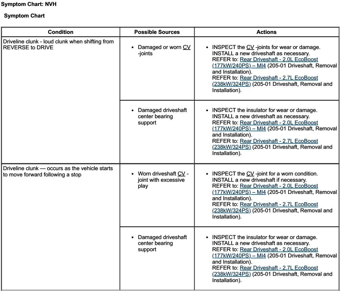
Clunk coming from rear middle of 19 Edge when accelerating?
Haz replied to eric1's topic in 2019-Current Edge & Nautilius
Welcome to the Forum @T Griff! You may want to add your experience to this discussion... Edge Low Speed Surge/Buck - Transmission Good luck! -
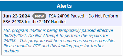
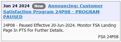
Dealers are being informed via Ford's Professional Technician System (PTS) website to pause their actions under Customer Satisfaction Program 24P08 due to software issues...


-
Clunk coming from rear middle of 19 Edge when accelerating?
Haz replied to eric1's topic in 2019-Current Edge & Nautilius
From the 2019 Edge Workshop Manual... Related sections of the 2019 Edge Workshop Manual are attached below as PDF documents... Good luck! Driveshaft - Diagnosis and Testing - 2019 Edge Workshop Manual.pdf Rear Driveshaft - 2.0L EcoBoost - Removal and Installation - 2019 Edge Workshop Manual.pdf Rear Driveshaft - 2.7L EcoBoost - Removal and Installation - 2019 Edge Workshop Manual.pdf
-
This Special Service Message was issued in September, 2020... SSM 49156 2017-2020 Various Vehicles - Speed Compensated Volume Operation Some 2017-2020 Ford and Lincoln vehicles may exhibit a customer concern of a perceived inoperative or reduced speed compensated volume function. Do not compare speed compensated volume operation with other vehicles as system operation varies between vehicle lines, model years and audio systems. To determine if the system is operating properly, drive the vehicle at constant highway speeds with the audio system at a medium to high volume level and switch the speed compensated volume system setting from off > high > off. If an increase in volume is observed when switching the system from off > high the system is operating properly. If there is no discernible change, refer to Workshop Manual (WSM), Section 415-00 for further diagnostics. The following information is from the 2019 Edge Workshop Manual... Audio Front Control Module (ACM) Operation The ACM receives vehicle speed information, used to adjust audio volume with different vehicle speeds, from the PCM over the CAN . PINPOINT TEST F: THE SPEED COMPENSATED VOLUME DOES NOT OPERATE CORRECTLY Introduction Normal Operation and Fault Conditions REFER to: Information and Entertainment System - Overview (415-00 Information and Entertainment System - General Information, Description and Operation). Possible Causes Speed compensated volume setting Speed signal concern Network communication concern ACM F1 CHECK THE SPEEDOMETER OPERATION Verify speedometer operates correctly. Does the speedometer operate correctly? Yes GO to F2 No REFER to: Instrumentation, Message Center and Warning Chimes (413-01 Instrumentation, Message Center and Warning Chimes, Diagnosis and Testing). F2 CHECK THE SPEED COMPENSATED VOLUME SETTING NOTE: Refer to the Owner Literature to access the speed compensated volume settings. Turn the speed compensated volume off. Operate the audio system in AM / FM mode. Drive the vehicle at various speeds and observe the speaker volume. Set the speed compensated volume to maximum compensation. Operate the audio system in AM / FM mode. Drive the vehicle at various speeds and observe the speaker volume. Does the volume remain constant with the speed compensated volume turned off, and increase and decrease with vehicle speed with the speed compensated volume set to maximum? Yes The system is operating correctly at this time. INFORM the vehicle owner in the correct usage of the speed compensated volume feature. No GO to F3 F3 CHECK FOR COMMUNICATION DIAGNOSTIC TROUBLE CODES (DTCS) Using a diagnostic scan tool, carry out the ACM self-test. Are any Diagnostic Trouble Codes (DTCs) present? Yes REFER to the ACM DTC Chart in this section. No For vehicles equipped with the 6 or 9 speaker system, GO to F5 For vehicles equipped with the 12 speaker system, GO to F4 F4 CHECK FOR CORRECT DSP (AUDIO DIGITAL SIGNAL PROCESSING MODULE) OPERATION Ignition OFF. Disconnect and inspect all the DSP connectors. Repair: Corrosion (clean module pins or install new connectors or terminals) Damaged or bent pins (install new terminals or pins) Pushed-out pins (install new pins as necessary) Reconnect the DSP connectors. Make sure they seat and latch correctly. Operate the system and determine if the concern is still present. Is the concern still present? Yes CHECK OASIS for any applicable service articles: TSB , GSB , SSM or FSA . If a service article exists for this concern, DISCONTINUE this test and FOLLOW the service article instructions. If no service articles address this concern, INSTALL a new DSP . REFER to: Audio Digital Signal Processing (DSP) Module (415-00 Information and Entertainment System - General Information, Removal and Installation). No The system is operating correctly at this time. The concern may have been caused by module connections. ADDRESS the root cause of any connector or pin issues. F5 CHECK FOR CORRECT ACM (AUDIO FRONT CONTROL MODULE) OPERATION Ignition OFF. Disconnect and inspect all the ACM connectors. Repair: Corrosion (clean module pins or install new connectors or terminals) Damaged or bent pins (install new terminals or pins) Pushed-out pins (install new pins as necessary) Reconnect the ACM connectors. Make sure they seat and latch correctly. Operate the system and determine if the concern is still present. Is the concern still present? Yes CHECK OASIS for any applicable service articles: TSB , GSB , SSM or FSA . If a service article exists for this concern, DISCONTINUE this test and FOLLOW the service article instructions. If no service articles address this concern, INSTALL a new ACM . REFER to: Audio Front Control Module (ACM) (415-00 Information and Entertainment System - General Information, Removal and Installation). No The system is operating correctly at this time. The concern may have been caused by module connections. ADDRESS the root cause of any connector or pin issues. The above Pinpoint Test and several referenced 2019 Edge Workshop Manual sections are attached below as PDF documents if fuller diagnostic efforts are necessary... Good luck! DIAGNOSTIC PINPOINT TEST ''F'' - THE SPEED COMPENSATED VOLUME DOES NOT OPERATE CORRECTLY - 2019 Edge Workshop Manual.pdf Audio Digital Signal Processing (DSP) Module - Removal and Installation - 2019 Edge Workshop Manual.pdf Audio Front Control Module (ACM) - Removal and Installation - 2019 Edge Workshop Manual.pdf Front Controls Interface Module (FCIM) - Removal and Installation - 2019 Edge Workshop Manual.pdf Front Display Interface Module (FDIM) - Removal and Installation - 2019 Edge Workshop Manual.pdf Loadspace Trim Panel - Removal and Installation - 2019 Edge Workshop Manual.pdf

-
Additional documents... Good luck! Inline Harness Connector - Connector C214 Location - 2020 Edge.pdf Inline Harness Connector - Connector C214 Pins-Circuits Detail - 2020 Edge.pdf Audio Digital Signal Processing (DSP) Module - Removal and Installation - 2020 Edge Workshop Manual.pdf Front Controls Interface Module (FCIM) - Removal and Installation - 2020 Edge Workshop Manual.pdf Front Display Interface Module (FDIM) - Removal and Installation - 2020 Edge Workshop Manual.pdf Audio Front Control Module (ACM) - Removal and Installation - 2020 Edge Workshop Manual.pdf
-
Regarding your interest in a true switched power source, perhaps the AM/FM Antenna Amplifier power circuit can provide you what you're seeking, since I expect the antenna amplifier would only be powered when the audio system is operating. Relevant sections from the 2020 Edge Workshop & Wiring Manuals are attached as PDF documents below and in an immediately following post, due to Forum file attachment limitations... Inline Harness Connector - Connector C411 Location Alternative View - 2020 Edge.pdf Audio Front Control Module (ACM) - Connector C240A - Location - 2020 Edge.pdf Inline Harness Connector - Connector C411 Location - 2020 Edge.pdf Inline Harness Connector - Connector C411 Pins-Circuits Detail - 2020 Edge.pdf AM-FM1 Antenna Amplifier Power - Connector C9021A Location - 2020 Edge.pdf AM-FM1 Antenna Amplifier Power - Connector C9021A Pin-Circuit Details - 2020 Edge.pdf Audio Front Control Module (ACM) - Wiring Diagram - 2020 Edge.pdf AM-FM1 Antenna Amplifier - Removal and Installation - 2020 Edge Workshop Manual.pdf Audio Front Control Module (ACM) - Connector C240A - Pins-Circuits Details - 2020 Edge.pdf

-
The front license plate requirement in Ohio was eliminated on July 1, 2020, so there's no need to mount it, unless your wife has a personalized aftermarket plate for her new Edge. With that said, the bracket is pop-riveted to the upper bumper cover, on center with the grille's Ford logo... Good luck!
-
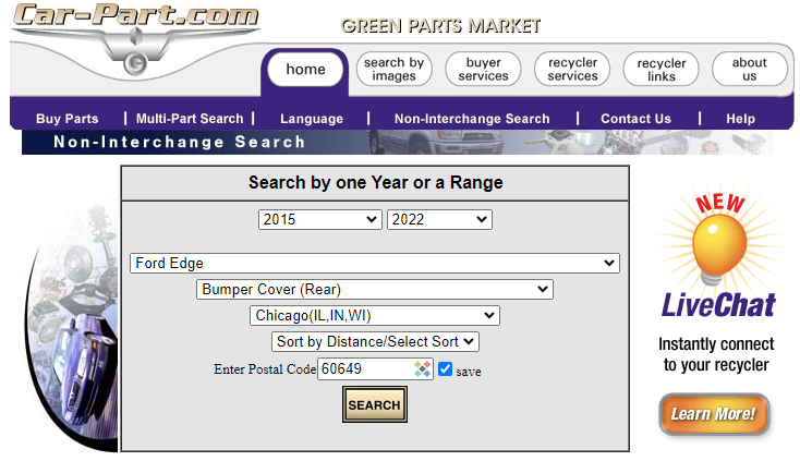
If the OEM Service parts supply has been exhausted, then you might try tapping into the Salvage Yard used parts market. Understandably, the Car-Parts.com used parts search engine lacks a specific identifier for rear bumper air deflector, but a decent starting point may be searching for rear bumper covers and then communicating with the Salvage Yard using images from the Forum discussion thread to ensure the vehicle might have been equipped with an air deflector that your looking for. A non-Trailer Tow deflector should also work for you with a little trimming, per Forum member @chipdog4's advice in this post. 2015 to 2022 model year Edges should be a good target, and the search I ran for the Chicago-metro area yielded many rear bumper covers, though you could select a wider area... Good luck!
-
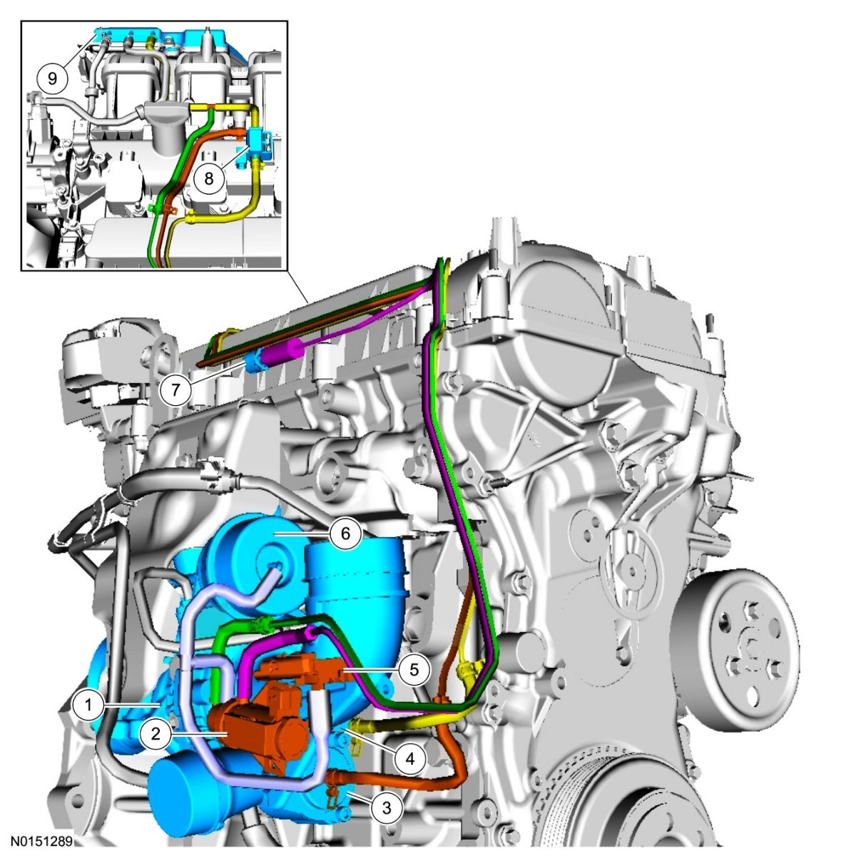
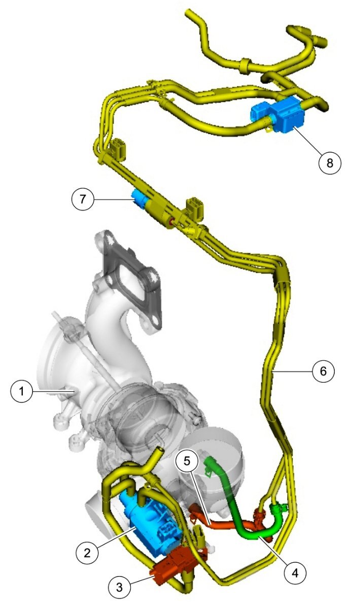
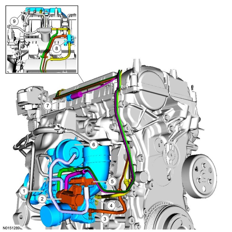
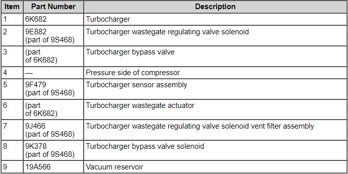
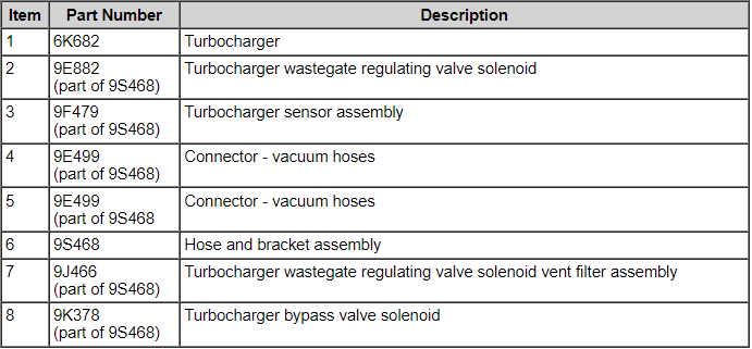
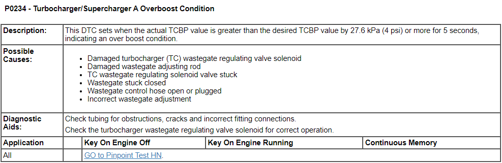
Welcome to the Forum @59panman! Turbocharger-related component illustrations from the 2012 Edge Workshop Manual... From the Ford Powertrain Control/Emission Diagnosis Manual for 2012 Ford Gasoline Engines... Pinpoint Test HN, and other supporting sections from 2012 Edge Workshop Manual and 2012 Edge Wiring Resource are attached below as PDF documents... Good luck! Turbocharger - Description and Operation - 2012 Edge Workshop Manual.pdf Turbocharger System - Diagnostic Pinpoint Test HN - Ford PC-ED Manual for 2012 Gasoline Engines.pdf Turbocharger Wastegate Vacuum Sensor - Wiring Diagram.pdf WASTEGATE VACUUM SENSOR - Connector C1644 Pins-Circuits Details - 2.0L EcoBoost - 2012 Edge.pdf WASTEGATE VACUUM SENSOR - Connector C1644 Location - 2.0L EcoBoost - 2012 Edge.pdf Turbocharger Wastegate Regulating Valve Solenoid and Bypass Valve - Wiring Diagram - 2.0L EcoBoost - 2012 Edge.pdf TURBOCHARGER (TC) WASTEGATE REGULATING VALVE SOLENOID - Connector C1246 Pins-Circuits Details - 2,0L EcoBoost - 2012 Edge.pdf TURBOCHARGER (TC) WASTEGATE REGULATING VALVE SOLENOID - Connector C1246 Location - 2.0L EcoBoost - 2012 Edge.pdf TURBOCHARGER BYPASS VALVE (TCBY) - Connector C1650 Pins-Circuits Details - 2.0L EcoBoost - 2012 Edge.pdf TURBOCHARGER BYPASS VALVE (TCBY) - Connector C1650 Location - 2.0L EcoBoost - 2012 Edge.pdf

-
Welcome to the Forum, @Autome! While the earlier Kia logo was contained in an oval, like Ford's... ...and early Kia Sedona minivans could be easily mistaken as being Ford Windstars... ...you would do much better to ask your Kia-vehicle question on a Kia-brand discussion site. Good luck!


-
While technically, the linked TSBs have not been extended to the 2024 model year, given your Edge ST's probable in-warranty status -- and especially if the noise is cold-start repeatable -- it would be worthwhile to have it evaluated by your dealer, though they will likely want it sitting at the dealership overnight to perform a truly cold-start the following day. Good luck!
-
Just checking, since inoperative cooling fans could explain A/C performance difference between vehicle stopped at idle and vehicle being driven at speed. Good luck!

-
Does the electric cooling fan(s) immediately run after you begin operating the A/C system? Good luck!
-
2011 Edge Limited , no power to windows ,No blue wire supply power .
Haz replied to Ford2504x4's topic in 2013 Edge & MKX
From the 2011 Edge Workshop Manual and Wiring Resource, posted here and also attached below as PDF documents... Pinpoint Test L: The Delayed Accessory is Inoperative Normal Operation The accessory delay relay is located in the Body Control Module (BCM) . When the ignition is in the ON position, the BCM activates the accessory delay relay by grounding the relay coil. When the ignition is turned to the OFF position, the BCM continues to ground the accessory delay relay coil for approximately 10 minutes, or until a front door is opened. When the accessory delay relay is active, it supplies voltage to the power window system. DTC B131A:12 (Delayed Accessory Power: Circuit Short To Battery) — sets when the BCM senses a short to voltage on the accessory delay relay control circuit. DTC B131A:14 (Delayed Accessory Power: Circuit Short To Ground or Open) — sets when the BCM senses an open or short to ground on the accessory delay relay control circuit. This pinpoint test is intended to diagnose the following: Door ajar switches Accessory delay relay BCM PINPOINT TEST L : THE DELAYED ACCESSORY IS INOPERATIVE NOTICE: Use the correct probe adapter(s) from the Flex Probe Kit when making measurements. Failure to use the correct probe adapter(s) may damage the connector. L1 CHECK FOR CORRECT OPERATION OF THE DOOR AJAR SWITCHES Open and close the front doors. Verify the interior lights turn on when the doors are open, and off when the doors are closed. Do the interior lights operate normally? Yes GO to L2. No REFER to Section 417-02 to diagnose the interior lighting and door ajar switches. L2 CHECK THE ACCESSORY DELAY RELAY Carry out the accessory delay relay component test. Did the accessory delay relay pass the component test? Yes GO to L3. No INSTALL a new accessory delay relay. CLEAR the DTCs. REPEAT the self-test. TEST the system for normal operation. L3 CHECK FOR CORRECT BCM OPERATION Disconnect all BCM connectors. Check for: corrosion. pushed-out pins. Connect all BCM connectors and make sure they seat correctly. Operate the system and verify the concern is still present. Is the concern still present? Yes INSTALL a new BCM . REFER to Section 419-10 for the removal and installation procedure. TEST the system for normal operation. No The system is operating correctly at this time. Concern may have been caused by a loose or corroded connector. CLEAR the DTCs. REPEAT the self-test. TEST the system for normal operation. Good luck! Power Window, Left Front - Wiring Diagram - 2011 Edge.pdf Window Motor Initialization - General Procedures - 2011 Edge Workshop Manual.pdf Master Window Adjust Switch - Component Testing Procedure - 2011 Edge.pdf Window Adjust Switch - Component Testing Procedure - 2011 Edge.pdf Body Control Module (BCM) - Illustration showing Accessory Delay Relay location - 2011 Edge.pdf Accessory Delay Relay, 5-Terminal - Component Testing Procedure - 2011 Edge.pdf Glass, Frames and Mechanisms - Diagnosis and Testing - 2011 Edge Workshop Manual.pdf -
Europe/United Kingdom 2022 Edge Rear Fog Lamps wiring diagrams, connector details and locations, attached below as PDF documents... Good luck! Rear Fog Lamps - Wiring Diagram #1 - 2022 Edge - United Kingdom.pdf Rear Fog Lamps - Wiring Diagram #2 - 2022 Edge - United Kingdom.pdf Rear Fog Lamps - Wiring Diagram #3 - 2022 Edge - United Kingdom.pdf Rear Fog Lamp, LH - Connector C436 Location, Rear View - 2022 Edge - United Kingdom.pdf Rear Fog Lamp, LH - Connector C436 Pins-Circuits Details - 2022 Edge - United Kingdom.pdf Rear Fog Lamp, RH - Connector C437 Location, Rear View - 2022 Edge - United Kingdom.pdf Rear Fog Lamp, RH - Connector C437 Pins-Circuits Details - 2022 Edge - United Kingdom.pdf Rear Fog Lamps - Inline Connector C438 Location, Inside View - 2022 Edge - United Kingdom.pdf Rear Fog Lamps - Inline Connector C438 Location, Rear View - 2022 Edge - United Kingdom.pdf
-
Welcome to the Forum, @bw228! Active Noise Control (ANC) microphones wiring diagram, connector details, locations, removal and installation info attached below as PDF documents... Good luck! Active Noise Control (ANC) Microphone - Removal and Installation - 2021 Edge Workshop Manual.pdf Active Noise Control (ANC) Microphones - Inline Connector C211 Pin-Circuit Details - 2021 Edge.pdf Active Noise Control (ANC) Microphones - Inline Connector C211 Location - 2021 Edge.pdf Active Noise Control (ANC) Microphones - Inline Connector C913, Pin-Circuit Details - 2021 Edge.pdf Active Noise Control (ANC) Microphones - Inline Connector C900, Pin-Circuit Details - 2021 Edge.pdf Active Noise Control (ANC) Microphones - Inline Connector C913 Location - 2021 Edge.pdf Active Noise Control (ANC) Microphones - Inline Connector C900 Location - 2021 Edge.pdf Active Noise Control (ANC) Microphones - Wiring Diagram - 2021 Edge.pdf Active Noise Control (ANC) Microphone - Rear, Connector C9928 - 2021 Edge.pdf Active Noise Control (ANC) Microphone - Right Front, Connector C9927 - 2021 Edge.pdf Active Noise Control (ANC) Microphone - Left Front, Connector C9926 - 2021 Edge.pdf
-
From the 2024 Edge Workshop Manual... Auto-Start-Stop System The Auto-start-stop system helps reduce fuel consumption by automatically shutting off the vehicle’s engine while the vehicle is at a complete stop and restarting the engine when the brake pedal is released. The system can be disabled through the auto-start-stop control switch on the instrument panel centerstack. The Auto-start-stop system is automatically enabled whenever the ignition is turned on. The engine automatically restarts when: the brake pedal is released. the Auto-start-stop system is disabled through the auto-start-stop control switch on the instrument panel centerstack. the battery has a low state of charge. it is necessary to maintain interior comfort. the blower fan speed is increased or the climate control temperature is changed. an electrical accessory is turned on or plugged in. there is low brake vacuum. The Auto-start-stop system may not turn the engine off under these conditions: the HVAC system is in A/C, heat or defrost modes. the rear defroster is on. the battery has a low state of charge. the battery temperature is below 5°C (41°F) or above 60°C (140°F). the engine temperature is below 46°C (115°F). the engine temperature is below 60°C (140°F) and the HVAC system is in heat mode. the gear selector is not in Drive or Sport Mode. the steering wheel is turned rapidly or is at a sharp angle. vehicle speed of greater than 4 km/h (2.5 mph) for more than 2 seconds has not occurred. the vehicle is on a steep road grade. elevation is approximately above 3,048 meters (10,000 feet). And... Direct Current/Direct Current (DC/DC) Converter Control Module - System Operation and Component Description System Diagram System Operation Network Message Chart Broadcast Message Originating Module Message Purpose Engine status PCM Used to indicate the type of cranking event occurring. If the signal is state 2, Engine Auto Stopped, then the next commanded crank is to be supported. If the signal is state 0, Engine Off, the next crank will be a key crank and the Direct Current/Direct Current (DC/DC) converter control module will not support. The Direct Current/Direct Current (DC/DC) converter control module, also known as the Voltage Quality Module (VQM), is responsible for boosting battery voltage to specific components on vehicles equipped with the auto-start-stop system. When the ignition is turned on the Direct Current/Direct Current (DC/DC) converter control module initializes after receiving the Run/Start power feed from the BCM controlled run/start relay. While in stand-by mode the Direct Current/Direct Current (DC/DC) converter control module performs self-diagnostics and is not producing any boost output voltage. The Direct Current/Direct Current (DC/DC) converter control module is simply passing battery voltage straight through to downstream loads when it is in stand-by mode. The Direct Current/Direct Current (DC/DC) converter control module continuously communicates it's status to the PCM via High Speed Controller Area Network (HS1-CAN). If the Direct Current/Direct Current (DC/DC) converter control module is overloaded, overheated, or other faults are present the PCM disables the auto-start-stop system. If a fault is detected, the PCM may restart the engine if an auto-start-stop event is already in progress. During an auto-start-stop event the engine shuts down automatically after vehicle speed is zero. As the engine begins shutting down, there is an initial battery voltage drop due to the engine shutting off and the alternator no longer providing output current. Once the engine is no longer spinning, the electrical system is fully supported by the vehicle battery. The electrical load present in the engine off phase of the auto-start-stop event causes a gradual decline in battery voltage. This gradual decline of battery voltage is the second voltage transition. The third voltage transition occurs during the engine restart. The system voltage drops, followed by the system voltage increasing to the regulation voltage point determined by the alternator output. Prior to the engine restart, the PCM sends a low-side drive command to the the low voltage Direct Current/Direct Current (DC/DC) converter. The low voltage Direct Current/Direct Current (DC/DC) converter is switched into Boost mode to stabilize/boost its output until the engine has started and system voltage regulation is established by the alternator. The converter provides the stabilized or boost output voltage until one of the following occurs: Boost time exceeds 5 seconds System input voltage exceeds targeted output The Direct Current/Direct Current (DC/DC) converter control module has full bypass or stand-by mode functionality within an input of 6V-16V. The Direct Current/Direct Current (DC/DC) converter control module must be able to provide the boosted voltage with a minimum 6V power net input voltage. If the supply voltage goes outside the voltage range, the Direct Current/Direct Current (DC/DC) converter control module recovers without user intervention when the supply voltage returns to the normal operating range. The Direct Current/Direct Current (DC/DC) converter control module determines the stabilized output voltage to be targeted by continuously measuring the Direct Current/Direct Current (DC/DC) converter control module input voltage. Prior to the restart event, the Direct Current/Direct Current (DC/DC) converter control module receives the RE-CRANK signal and sets the boosted output voltage target to be equivalent to the measured input voltage. This makes sure the output voltage to the supported loads does not change. Malfunction of the system does not lead to non-function of other vehicle systems. The system enters bypass mode if: a thermal overload condition exists. there is a Direct Current/Direct Current (DC/DC) converter control module failure. the output voltage is more than 1V below input voltage and voltage boost is not available. The Direct Current/Direct Current (DC/DC) converter control module self-protects against overheating and self-recovers without user interaction after an overheating event and is internally protected from short-circuits. Component Description The Direct Current/Direct Current (DC/DC) converter control module is connected in series between the high current fuse box and a select number of non-safety electrical loads. The majority of the loads are fused through the BCM and remaining loads are not fused and are switched on by a smart transistor located internal to the Direct Current/Direct Current (DC/DC) converter control module. The smart transistor acts as a fuse and shuts off power in the event of a short to ground. The Direct Current/Direct Current (DC/DC) converter control module has a dedicated body ground and incorporates a hardwired signal circuit from the PCM which notifies the Direct Current/Direct Current (DC/DC) converter control module prior to the engine cranking during an auto-start event. Good luck!