chipworkz
-
Posts
84 -
Joined
-
Last visited
-
Days Won
7
Content Type
Profiles
Forums
Gallery
Everything posted by chipworkz
-
Puddle Lights
chipworkz replied to tangelo2007's topic in Glass, Lenses, Lighting, Mirrors, Sunroof (BAMR), Wipers
The bulb itself is in the enclosed housing. Your two choices are to either replace the puddle light with a stock unit or follow the same procedures as replacing it with the LED bulb but just use a standard bulb. -
Switchback Issue
chipworkz replied to smb56's topic in Glass, Lenses, Lighting, Mirrors, Sunroof (BAMR), Wipers
Just because I wanted them both in a central location that I could easily get to and unplug them if I wanted to. I was able to hide the wiring pretty well coming from that location and as you can see from the passenger side shot, you would have to look pretty hard to notice anything was done. -
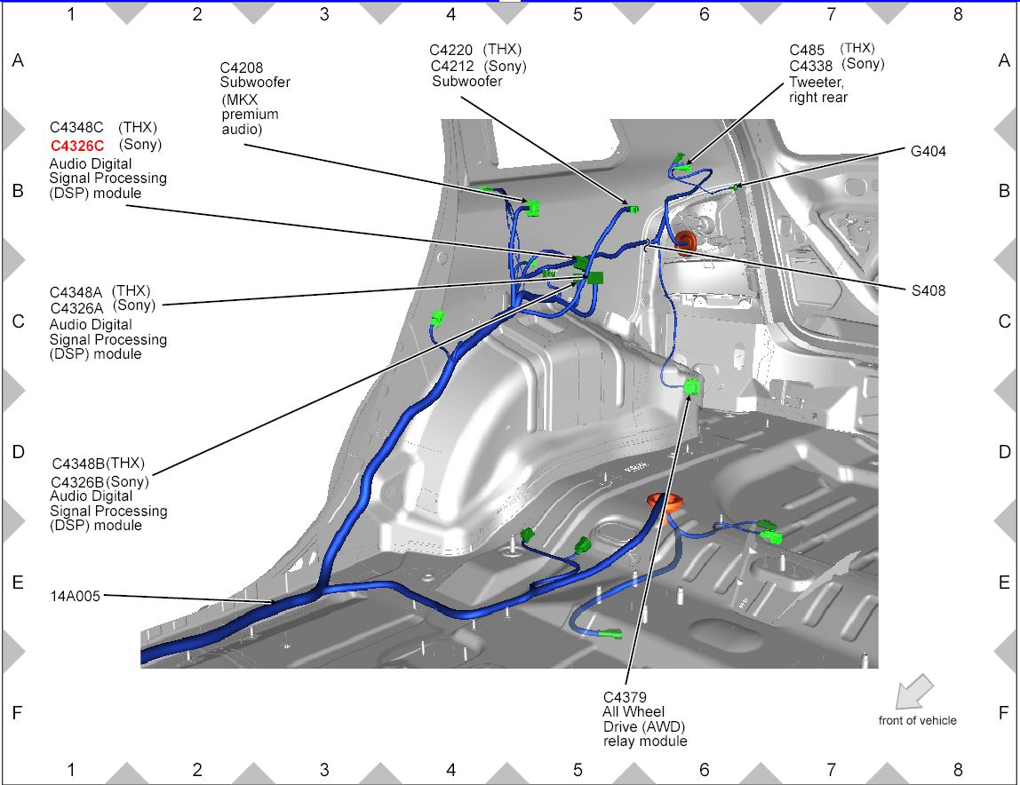
Wiring Diagrams for 2013 SEL "6" Speaker System
chipworkz replied to Rmmcgrew's topic in Audio, Backup, Navigation & SYNC
Hi Wizard, I don't want to get into trouble or get the site into trouble. If sharing this information for personal use here is a no no, I will take them down. -
It still may not be the bulb itself but that is where you need to start. Also check the socket, many have reported that the Ford sockets fit a little loose on replacement bulbs so make sure the metal tabs are fitting snug on the bulb as well. If both of those items check out, I can post the diagrams showing all the connector points so you can check those as well if that is something that you would want to do.
-
When it is not working, does that side blink faster or still the normal flash rate? If it is not seeing the filament in the bulb then it should. As akirby said, the bulb would be the first place to start. I have seen bulbs do this before as well but normally not for to long before they finally go out completely.
-
Switchback Issue
chipworkz replied to smb56's topic in Glass, Lenses, Lighting, Mirrors, Sunroof (BAMR), Wipers
So the resistors did in fact correct the issue with my switchbacks as well. Here are a few pics of my install. I mounted them on a plate I threw together real quick so I won't worry about them getting hot. They do get pretty warm after a few minutes which could happen if you have the flashers turned on when broken down or something. I soldered the one side to the positive wire and the other side to the chassis ground. They can be removed in a few minutes if I needed to go back to standard bulbs. -
Wiring Diagrams for 2013 SEL "6" Speaker System
chipworkz replied to Rmmcgrew's topic in Audio, Backup, Navigation & SYNC
Tphord, let me know if this works for you. If you only have the 6 speaker system, I am not sure if there will be any of the audio wiring shown in the Rear Quarter diagram.


-
I finally got it off today. I just could not get it loose with my hands only. It didn't matter how hard I pulled the bottom would not come loose. I used a body panel removal tool to insert between the housing and body and pulled it towards the rear of the car. The bottom finally popped out with no damage to the housing or paint. I do have a couple of scratches below the light from all the wiggling around that I will need to touch up. As suggested, I did put a little grease on the pegs so it will be easier to get off next time.
-
Switchback Issue
chipworkz replied to smb56's topic in Glass, Lenses, Lighting, Mirrors, Sunroof (BAMR), Wipers
Thanks for the report Jeff, I just bought these swtichbacks http://smile.amazon.com/gp/product/B00IZSWHFA/ref=oh_aui_detailpage_o01_s00?ie=UTF8&psc=1 and they stayed amber just like yours. It is was around 10:30pm when I opened the package and plugged it in but my initial thought was exactly what you found with your test. It would only go white when I first plugged it in before the turn circuit made contact. I am glad to know that the resistors are going to fix it. I already have them and will install them to make sure. I really liked the looks of these since all 60 leds are on for white and then switch to amber. I haven't seen any others that do this. The others are 30 white and 30 amber from what I have come across. -
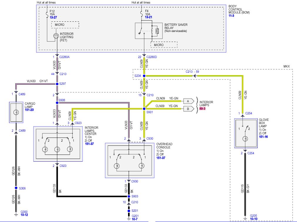
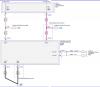
This is an old thread but to address the original question, yes there are two fuses. One for the dome lights (F12) and one for the on demand or switched (switch at the light) lights (F4). The switch on the dash activates the F12 circuit so it is the same as opening the door. See the attached diagram.

-
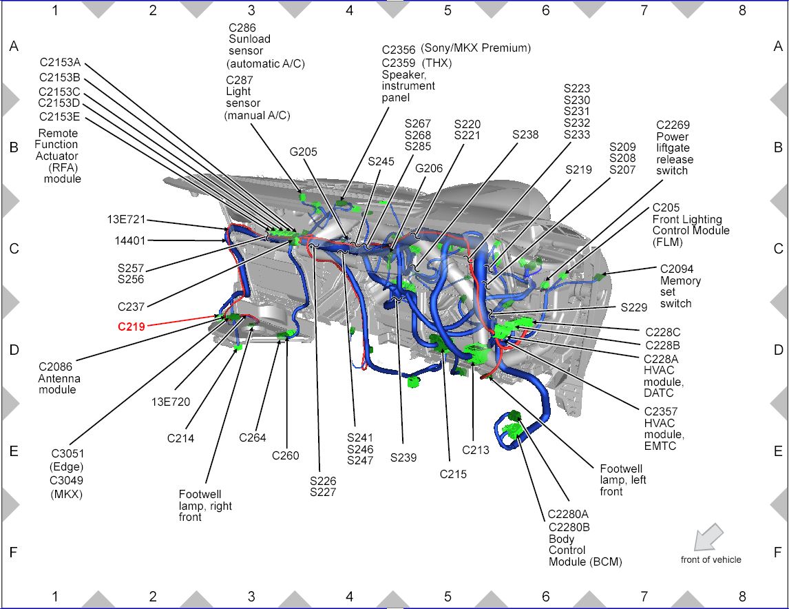
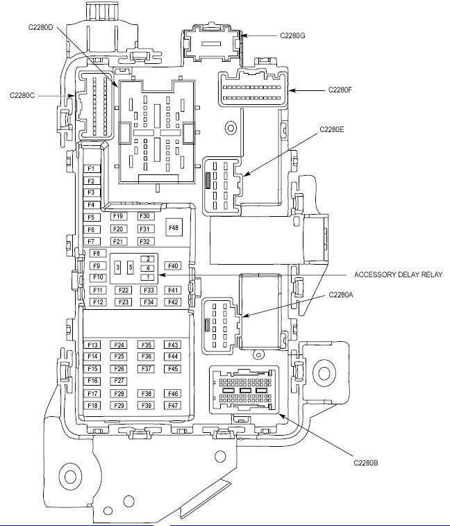
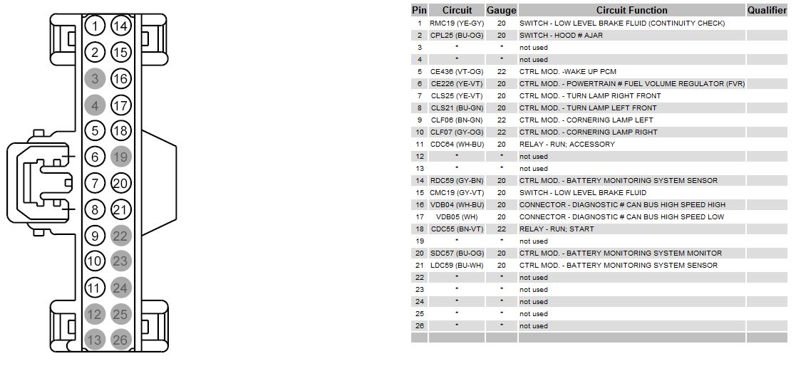
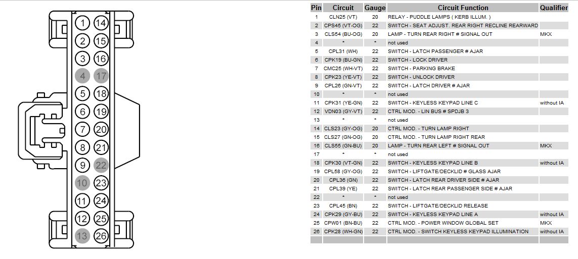
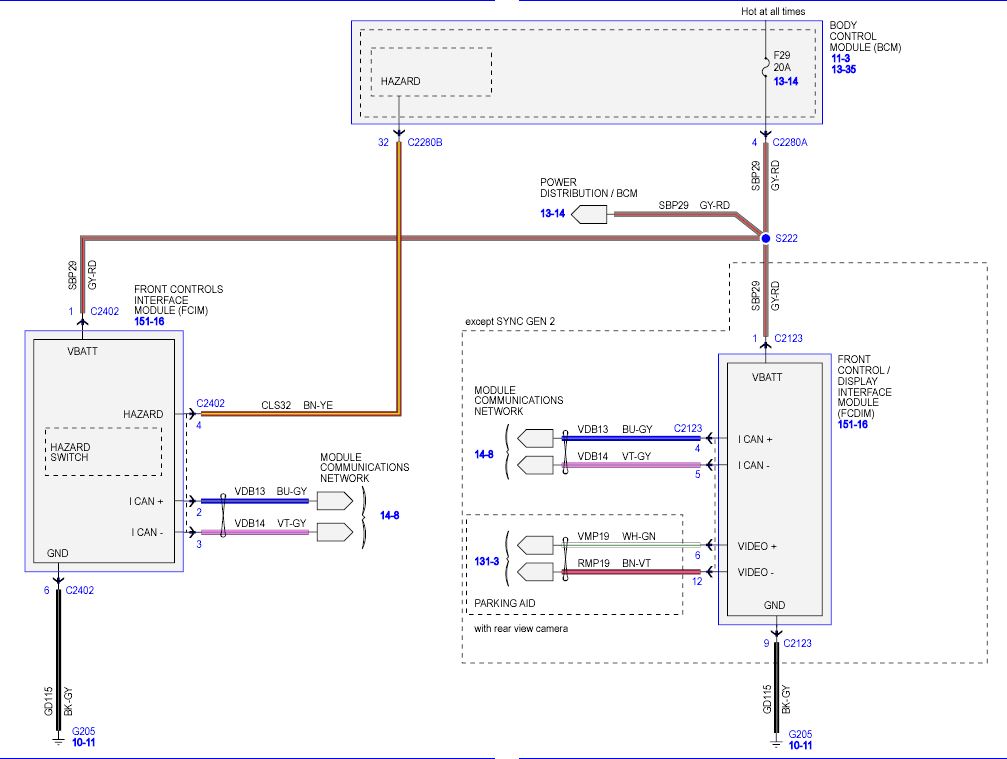
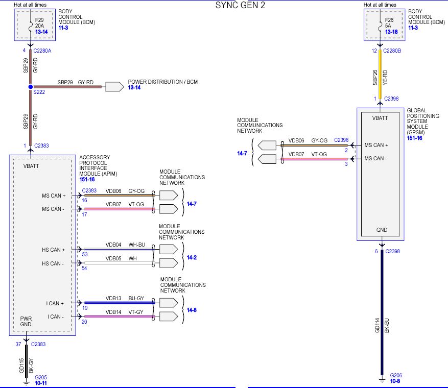
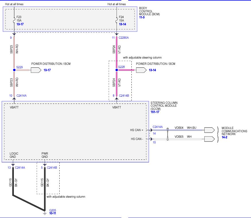
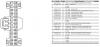
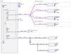
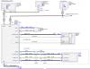
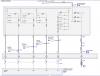
Since this thread is still going, here is some more info to go alone with all of Wizards great instructions. Along with the diagrams of the wiring and wire colors, I have included the BCM connectors and pin layout. The connector layouts are as if you had the connector unplugged and looking at the front of it. (the side that gets plugged in) So it is basically upside down if you were looking at the BCM with the connectors plugged in to it in the car. So looking at the wire plugged in, C2280C Pin 1 is the lower left corner and C2280F Pin 1 is in the upper left corner. Hope this helps,


-
Led Puddle Lights
chipworkz replied to Muser99's topic in Glass, Lenses, Lighting, Mirrors, Sunroof (BAMR), Wipers
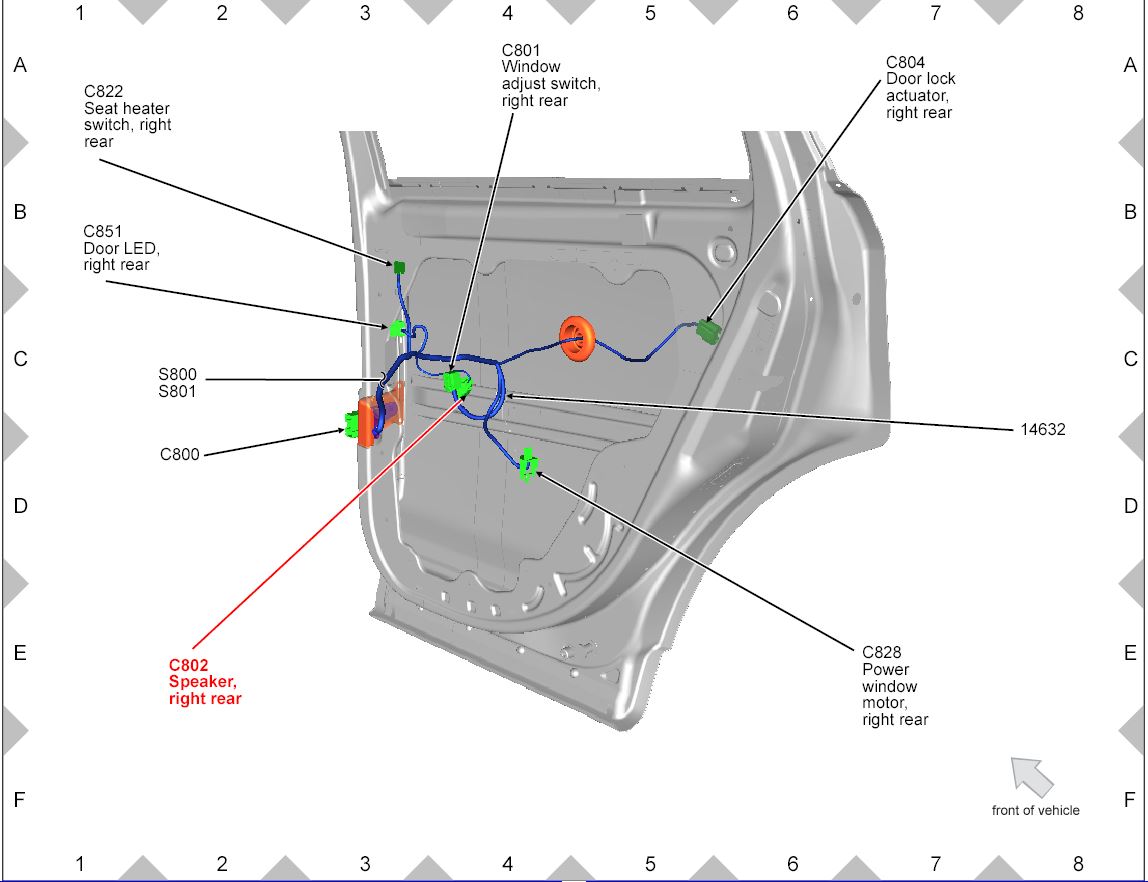
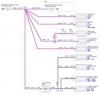
There is lots of info out here already on the puddle lights so I didn't bother to do a write up but I just did mine. I bought the 5 watt Cree LED's from http://www.ebay.com/itm/230973307751?_trksid=p2059210.m2749.l2649&ssPageName=STRK%3AMEBIDX%3AIT and they are nice! WAY brighter that the original bulbs and they only draw 129 ma vs the stock dim bulbs that draw 380 ma. One thing to note is that they are listed as 31mm which is what the originals measure but these Cree's are actually 31.9mm They fit but you have to spread the prongs apart and work them back in once the bulb is in place. As far as taking apart the puddle lights, there is no need to cut or saw anything. The job is pretty easy overall and won't be hard to do for anyone mechanically inclined. I used a little bit of Goof off around the parameter of where the lens meets the body. I just kept putting a little on and letting it set. After about 10 minutes or so, I used an X-Acto knife to to get in between the lens and body. Slowly work around the parameter prying it apart until you find an area the comes loose. Then you work from that spot and continue around and the lens comes off nice and clean with no damage. I am doing my rear puddle lights as well and bought these. http://www.ebay.com/itm/130474912171?_trksid=p2059210.m2749.l2649&ssPageName=STRK%3AMEBIDX%3AIT They color is just like the 5 watt Cree's and are also really bright. I may have to cut some of the LED's off, which you can do, so it isn't too bright. I am going to wait until I get them on before I cut off though. The attached Diagrams should help if you are doing the rear puddle light mods. I will upload some pictures after I get the rears put in this weekend. Here is the front 5 watt Cree bulb installed. Here are some pics of my rear puddle lights install. I ran the positive Red wire from the fuse box following the factory wire harness to the rear driver side door. I soldered the positive side and used a self tapping screw for the negative side as shown. I then continued the positive wire under the carpet under the rear seat over to the passenger side and then up to the passenger front door. I now have a positive feed for my rear puddle lights along with the supply for lighted door sills if I get them in the future. Notice that these slots that the wires feed up through both in Dan's video and my pictures are for the clips to fit in for the rear sill plate. Notice I cut the rubber grommets off so they are only on the backside of the wire. Be careful when installing the sill plate to make sure you don't catch the grommet or wires. There is just enough room for the clip to fit in the slots without pushing out the grommet. Here is the wire ending at the front passenger door. I put the heat shrink tubing on it to prevent any possible shorts.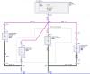

-
Shift to Park Warning when it's in Park
chipworkz replied to AmyLovesHerEdge's topic in All Wheel Drive (AWD)
Here is the cable adjustment procedures for the two transmission types. 6F35 Transmission Cable Adjustment.pdf 6F50-6F55 Transmission Cable Adjustment.pdf -
Shift to Park Warning when it's in Park
chipworkz replied to AmyLovesHerEdge's topic in All Wheel Drive (AWD)
If anyone is interested in the Cable Adjustment Procedure let me know. -
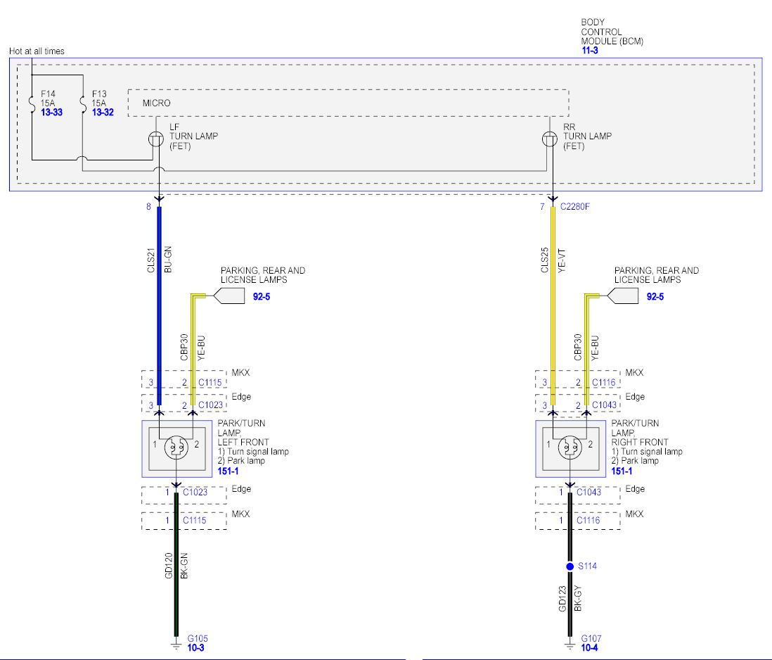
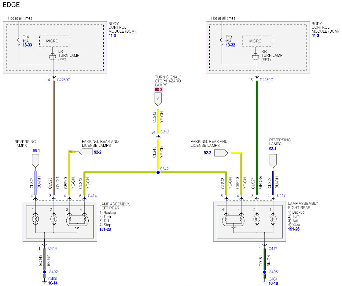
As I am starting to post here, you may notice that I like details and to know why things work the way they work. If anyone finds that I have posted incorrect information, please let me know. So I just ordered my LED Switchbacks for the front of my Edge. I was reading on the resistors that everyone is installing to prevent the Hyperflash from occurring. The majority of everyone uses the 50 watt 6 ohm resistors. Some older posts showed a person using a 3.8 ohm ceramic resistor so it got me curious. Why is it a 6 ohm resistor is used vs the 3.8 ohm or some other value. First lets take a look at what specs the 3457 bulb has. 3457: category: Miniature volt: 12.8 / 14 amp: 2.23 / 0.59 watt: 28.5 / 8.26 base: W2.5x16q glass: S8 filament: C6/C6 fil.res.: 5.74 / 23.7 ohm m.o.l.: 2.09 inch (53MM) l.c.l.: 1.1 inch (27.9MM) i.lumens: 503 / 37.7 cp: 40 / 3 d.hours: 400 / 5000 The car wants to see roughly 28.5 watts at 12.8 volts to think that the bulb is in place and working. So we need the combination of the resistor and the LED bulb to be roughly 28.5 watts. I don't have my LED bulbs yet to measure its amp draw so for now lets just look at the resistor. For reference we will use 12.8 volts. For the resistor, we know it is 6 ohms. First we need to find how much current the 6 ohm resistor will draw at 12.8 volts. To do this we will use Ohm's law which is I(amperage) = V(Voltage)/R(Resistance) So it is I=12.8/6 which is a current of 2.133 amps. Now to find the wattage we use the formula I(Amperage)=P(Power or Wattage)/V(Voltage) So we have 2.133=P/12.8 or 12.8x2.133=P which is a wattage of 27.47 So if we only take into account the resistor, we see that it alone is 27.47 watts which is very close to the desired 28.5 watts. Once I get my bulbs and test them, I will update the post with what the total wattage is that the car will be seeing between the bulb and resistor together. Now why do we need one resistor per bulb you might ask since the front and back lights are both flashing at the same time? Can't we just use one resistor of the proper size to make up for both bulbs? We that was my thinking until I looked at the wiring diagram. As we know our Edge's don't use a relay for the flasher like other cars. Each light connects to the BCM and its own transistor to control the blinking. This means that we need to treat each bulb individually. More info to come once I get my bulbs and do some more testing. Hope some of you find this interesting.

- 1 reply
-
- 1
-

-
Sorry omar302, I am not a Ford mechanic so I can only go by what the documentation says. It only lists those two options so I would assume that those are they only choices. I do have the Atuo Enginuity tool but I haven't connected it to my Edge yet to see what all it will do with it. I have only used in on my 99 F350. I haven't used it in the last year but it is a great tool. Here is the link if anyone wants to look into it. https://www.autoenginuity.com/
-
Dome light and trunk light not working
chipworkz replied to MoogLe's topic in Interior, A.C., Heat, Interior Trim
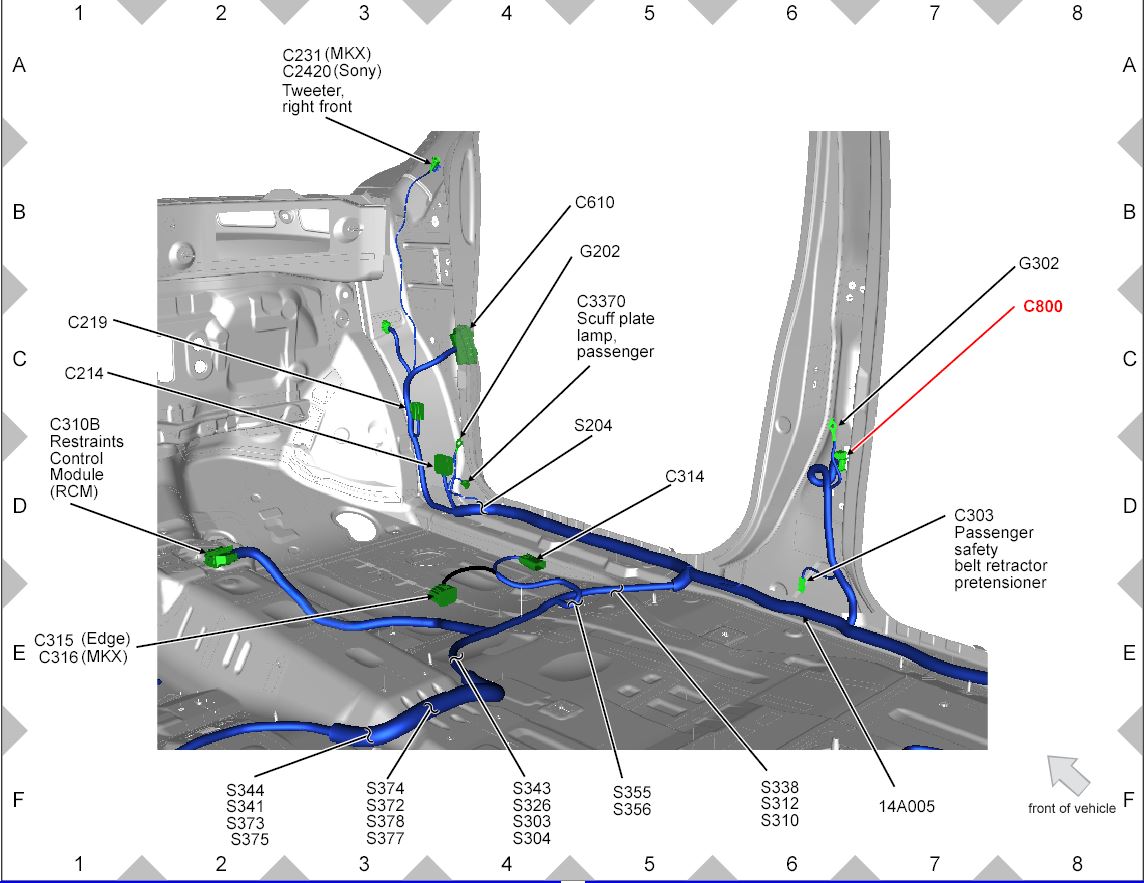
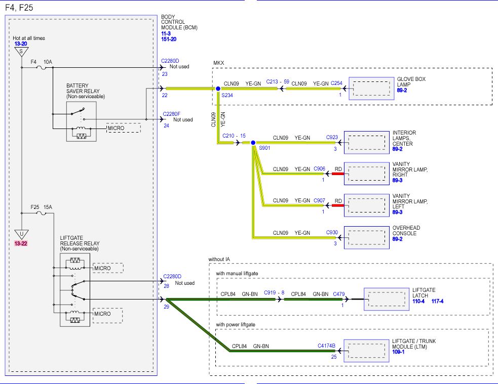
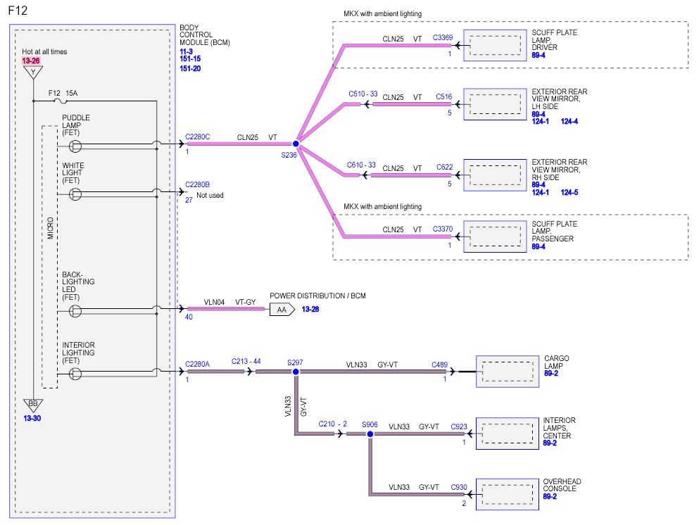
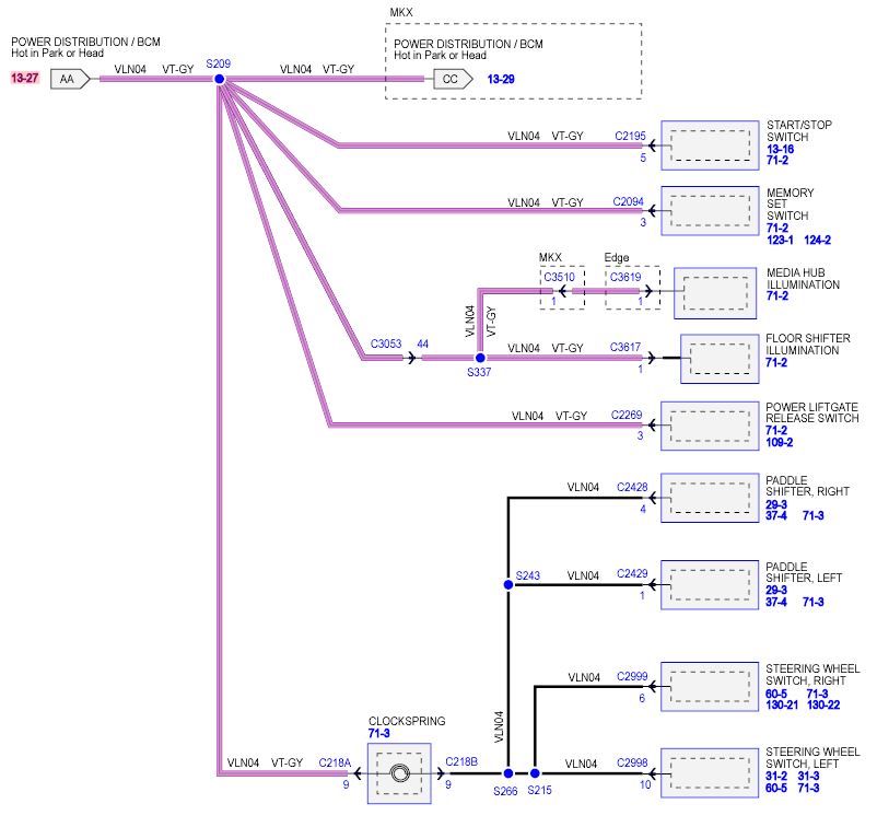
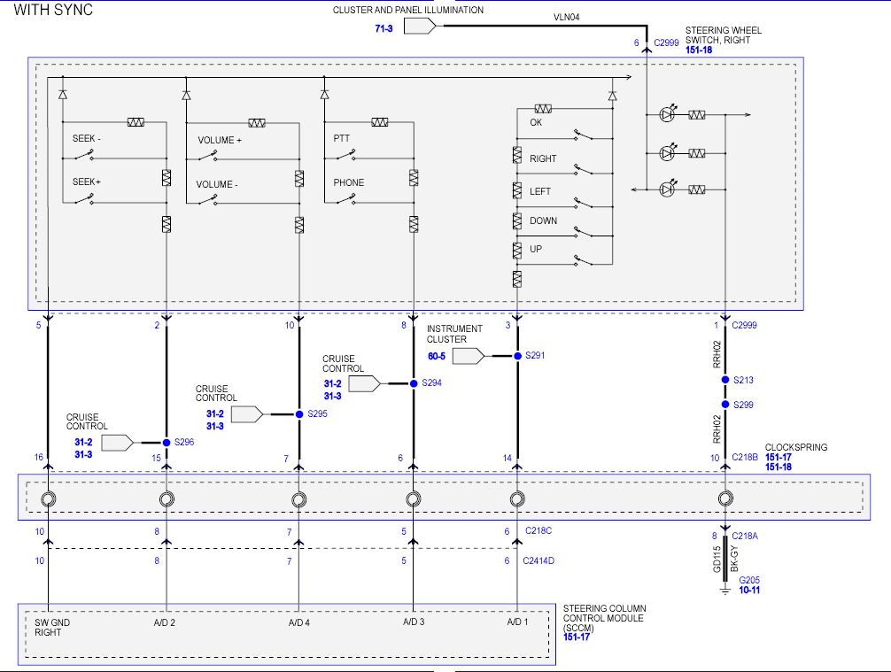
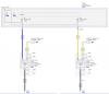
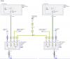
I know this thread is a little older but in case someone is looking for the information, here is the difference between Fuse #4 and Fuse #12. #12 is for the courtesy dome lights were as #4 is for the On Demand (Switched) dome lights. If you pull #12 only, the dome lights won't come on when you press the switch on the dash or open your door. You will still be able to hit the switches on the dome lights and turn on the on demand circuit since #4 is still in. See the attached diagrams for the circuit layout. Notice #12 is for more than just the dome lights. It is also for other back lighting like the steering wheel switches and media hub lighting for example. See the diagrams F12 and 13-37 for the complete circuit.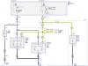
-
Best Interior LED Kit?
chipworkz replied to TMedge01's topic in Glass, Lenses, Lighting, Mirrors, Sunroof (BAMR), Wipers
For the Interior lighting, instead of buying all the different bulbs here and there, I just went with this kit instead. http://www.amazon.com/gp/product/B00HRMSU1K/ref=oh_aui_detailpage_o00_s00?ie=UTF8&psc=1 You can save a few bucks from searching for the different types on Ebay but this kit has all 10 bulbs as a kit and they look great. They give it a nice modern look without being overly bright. They are brighter that stock but not extreme where it will kill your passengers eyes. For the puddle lights, I haven't done them yet but will be getting them from DayTimeBrightLites as well. Here is what the lights look like that I linked to. I think they look pretty good. -
So there are a few Dead Battery threads going but in all of them that I read, there wasn't much info on doing anything more than either replacing the battery or taking it to the dealer. Well the other morning I woke up to a low battery that wouldn't start my car. The battery is just going on 3 years old and it is the original battery. I jump started it and drove it for almost 6 hours so the charge should have been back up to normal. The following morning, the voltage had dropped from 12.8 down to 10.7 and wouldn't start the car again. I did a quick current check by connecting my meter up to the negative cable and battery post before I disconnected the cable. At that moment, there was a 12.7 ma draw which is in the normal range. So with the age of the battery with it being the stock smaller battery, the easiest thing to do was to replace the battery which is what I did for a few reasons. First was the age and with only 12K Miles on the car over 3 years, it has had a lot of short runs. Second is I don't have remote start so I had the smaller Type 59 battery which is only 580 cca. I plan on putting in some stereo amps so I wanted to go with a bigger battery anyway. The remote start came with the bigger Type 65 battery so that is what I put in instead. It has a 850 cca rating and more reserve so if you are going to replace your battery and have the smaller Type 59, I would suggest you upgrade it to the Type 65 when you replace it. Only $99 dollars at Cosco for an Interstate battery with a full replacement of 42 months by the way. Just a quick note on the drain when I connected my new battery. When the battery is first connected, there was around a 2.8 amp draw for the first couple of minutes before it went back down to the 14 ma range. So if you are checking the drain when the cable is first connected, don't be alarmed to see even up to 7 amps or so while the lights are on or 2 to 3 amps when nothing appears to be on. Just give it a few minutes. So if I didn't simply have a bad battery, then I will continue to troubleshoot what is causing the drain. Here is a good article I found on the subject http://diagnosticnews.com/parasitic-battery-drains/ If you are changing your battery yourself, please note the bold section below. "NOTE: When the battery (or PCM) is disconnected and connected, some abnormal drive symptoms may occur while the vehicle relearns its adaptive strategy. The charging system set point may also vary. The vehicle may need to be driven to relearn its strategy. Disconnect the battery. For additional information, refer to Battery Disconnect in this section.Remove the bolt and the battery hold-down bracket. To install, tighten to 7 Nm (62 lb-in). Remove the battery.To install, reverse the removal procedure. Carry out the Battery Monitoring System (BMS) Reset using the scan tool after the battery is connected. If the BMS Reset is not carried out, it takes approximately 8 hours for the Body Control Module (BCM) to learn the new battery state of charge. During this 8 hour period, the vehicle must be undisturbed, with no doors opened or keyless entry button presses. If the vehicle is used before the BCM is allowed to learn the new battery state of charge, engine off load shedding can still occur and a message may be displayed." Here is the Ford Battery Drain Test procedure that I will be following if the problem still exists. "Battery Drain Test WARNING: Batteries contain sulfuric acid and produce explosive gases. Work in a well-ventilated area. Do not allow the battery to come in contact with flames, sparks or burning substances. Avoid contact with skin, eyes or clothing. Shield eyes when working near the battery to protect against possible splashing of acid solution. In case of acid contact with skin or eyes, flush immediately with water for a minimum of 15 minutes, then get prompt medical attention. If acid is swallowed, call a physician immediately. Failure to follow these instructions may result in serious personal injury. NOTE: No factory-equipped vehicle should have more than a 50 mA (0.050 amp) draw. NOTE: Many electronic modules draw 10 mA (0.010 amp) or more continuously. NOTE: Typically, a drain of approximately 1 amp is attributed to an engine compartment lamp, glove compartment lamp or interior lamp staying on continually. Other component failures or wiring shorts are located by selectively pulling fuses to pinpoint the location of the current drain. When the current drain is found, the meter reading falls to an acceptable level. If the drain is still not located after checking all the fuses, it may be due to the generator. Disconnect the generator and retest. NOTE: To accurately test the drain on a battery, an in-line ammeter must be used between the negative battery post and its respective cable. Use of a test lamp or voltmeter is not an accurate method. Make sure the junction box(es)/fuse panel(s) is accessible without turning on the interior lights or the underhood lights.Drive the vehicle at least 5 minutes and over 48 km/h (30 mph) to turn on and activate the vehicle systems.Allow the vehicle to sit with the key out of the ignition for at least 40 minutes to allow the modules to time out/power down.Connect a fused jumper wire (30A) between the negative battery cable and the negative battery post to prevent modules from resetting.Disconnect the negative battery cable from the negative battery post without breaking the connection of the jumper wire. NOTICE: To prevent damage to the meter, do not crank the engine or operate accessories that draw more than 10A. NOTE: It is very important that continuity is not broken between the battery and the negative battery cable when connecting the meter. If this happens, the entire 40-minute procedure must be repeated. Connect the battery tester between the negative battery cable and the post. The meter must be capable of reading milliamps and should have a 10-amp capability. NOTE: If the meter settings need to be switched or the test leads need to be moved to another jack, the jumper wire must be reinstalled to avoid breaking continuity. Remove the jumper wire.Note the amperage draw. Draw varies from vehicle to vehicle depending on the equipment package. Compare to a similar vehicle for reference.NOTE: If the vehicle sits for an extended period of time and the battery drains, there is the possibility of a control module staying alive and not going into sleep mode. If a module does stay alive, it can also result in battery drain. If a module is suspect, isolate individual modules by disconnecting each module one at a time and note if the excessive draw goes away. NOTE: For vehicles equipped with aftermarket bodies or boxes which contain electrical connections, disconnect the aftermarket to factory connections to isolate the body from the chassis. If the current draw is excessive, remove the fuses from the Battery Junction Box (BJB) one at a time and note the current drop. When the current level drops to an acceptable level after removing a fuse, the circuit containing the excessive draw has been located. The excessive draw can be isolated by continuing to pull sub system fuses. Do not reinstall the fuses until testing is finished. To correctly isolate each of the circuits, all of the fuses may need to be removed, then install one fuse and note the amperage draw, remove the fuse and install the next fuse. Continue this process with each fuse. Once the main circuit is identified, continue to remove the fuses from the Smart Junction Box (SJB) one at a time and note the current reading. Do not reinstall the fuses until testing is finished. To correctly isolate each of the circuits, all of the fuses may need to be removed, then install one fuse and note the amperage draw, remove the fuse and install the next fuse. Continue this process with each fuse. Check the wiring diagrams for any circuits that run from the battery without passing through the BJB or the SJB . If the current draw is still excessive, disconnect these circuits until the draw is found. Also, disconnect the generator electrical connections and retest if the draw cannot be located. The generator may be internally shorted, causing the current drain." I hope this helps some of you DIY type of people out there. I do have a bumper to bumper warranty which I will use if I can't figure out the issue in the end. That is if the new battery itself didn't fix the issue. I will update this thread if my problem continues and what I am doing to fix it.
-
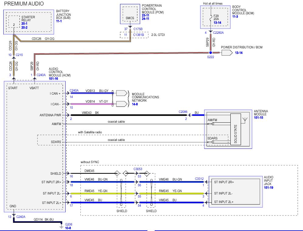
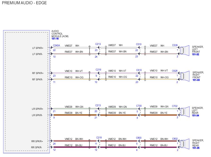
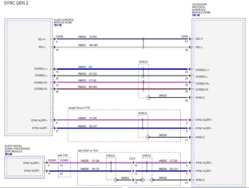
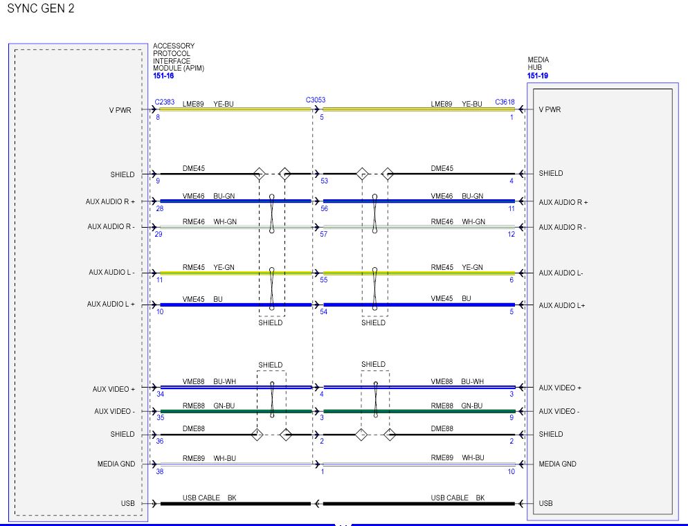
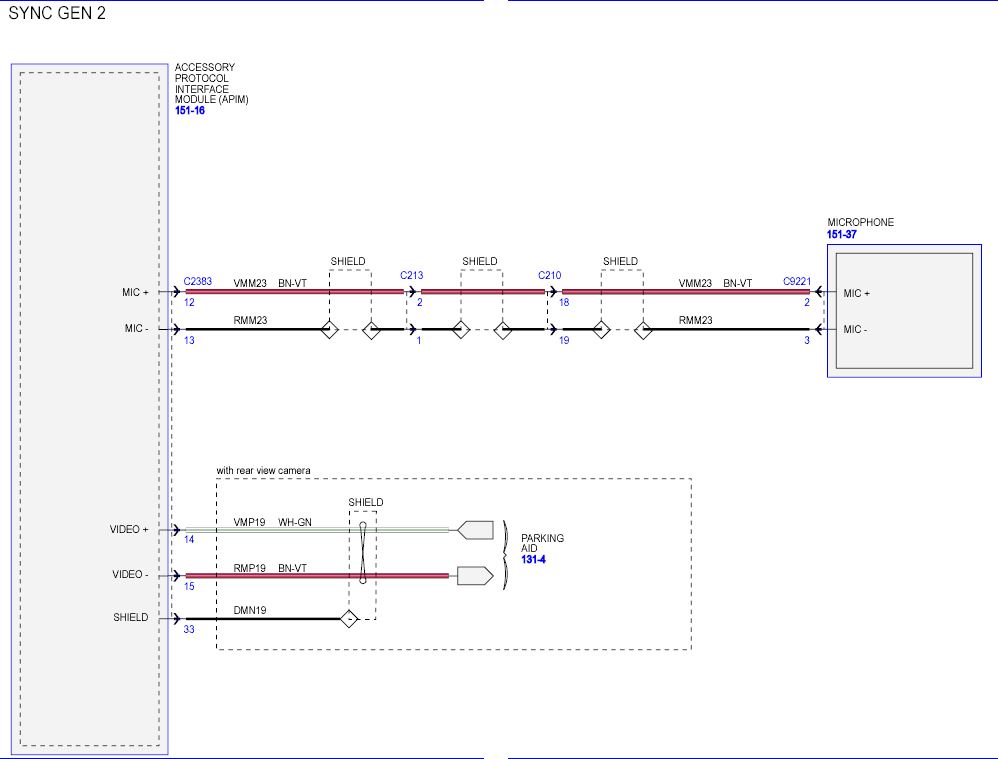
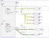
Wiring Diagrams for 2013 SEL "6" Speaker System
chipworkz replied to Rmmcgrew's topic in Audio, Backup, Navigation & SYNC
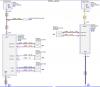
Here are the actual Diagrams. If you need any others, let me know. I am not sure why the thumbnails are out of order but oh well.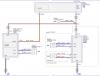


-
Another vote for 303 Aerospace. I just used it on my interior and the car looks incredible. I hate the high gloss of Armorall. The 303 gives it a really nice slight shine and not a high gloss at all.
-
Here are a couple of Videos on the installation. No it is not a direct plug and play install. https://www.youtube.com/watch?v=YecwqQrevKI https://www.youtube.com/watch?v=lSO3N2sZOhA
-
So I tried to remove my 2012 tail lights last night to get at the bulbs. I did a quick search to see how they are removed. I removed the screws and then tried to pull them straight out as the videos showed. I got the top stud to release but the bottom one is more like a barb and will NOT let go. I pulled as hard as I could while wiggling the light around and could not get it. I even used a putty knife behind the light to give it pressure as I pulled and still nothing. Why would Ford make it so hard to get these lights out? I am afraid of scratching up the paint just trying to get the lights out. Anyone have any special way of getting these things out? Thanks, Chris
-
Try what akirby suggested and also check what version MFT software you are running. If it is not the latest, it may have a compatibility issue with the Note 3 (Newer phone) vs the older phone you were using. I personally have never had any Bluetooth connection issues with my phone for the car or the other various Bluetooth devices I have used with it. My MFT version is the latest of 3.6.2 Regarding the lock screen, I haven't seen that as an issue either but you can try bumping up the screen timeout to 10 minutes to see if it happens while the screen is still on. Just don't leave it that way or her battery won't last to long. ;-) In the main (center Screen): Settings> Help> System Information> CCPU S/W Version Check the number in the middle: If it was 13171, then you have version 3.6.2 (latest North America) If it was 12285, then you have version 3.5.1 If it was 12156, then you have version 3.2.2 If it was 12023, then you have version 3.0.2 (the 1st “Performance upgrade” released in March 2012) Less than that, it is a very old version.
-
I have the Note 3 as well. I have not had the Bluetooth connection drop once I am in the car and it is connected. What I have seen, and this is the Note 3 issue not the car, is that IF the car is the only Bluetooth connection you are using, it will automatically connect when you get in the car. IF you use a Bluetooth headset with the phone and it is connected when you get in the car, you have to go into the phone and select "Sync" to change to connection over to the car instead of the headset. So without getting more details about what you mean by "Now the system won't stay connected to her phone." as in it drops the connection when driving vs not connecting when you get in the car, it is hard to say. If it isn't what I described as I have seen, does she use the phone with another Bluetooth device? Any issue with the phone staying connected to another device?