Wubster100
-
Posts
648 -
Joined
-
Last visited
-
Days Won
26
Content Type
Profiles
Forums
Gallery
Everything posted by Wubster100
-

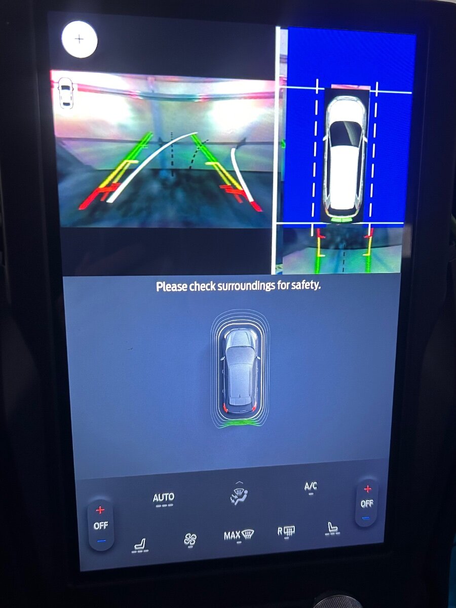
Retrofit 360 Camera Into Ford Edge
Wubster100 replied to Wubster100's topic in Accessories & Modifications
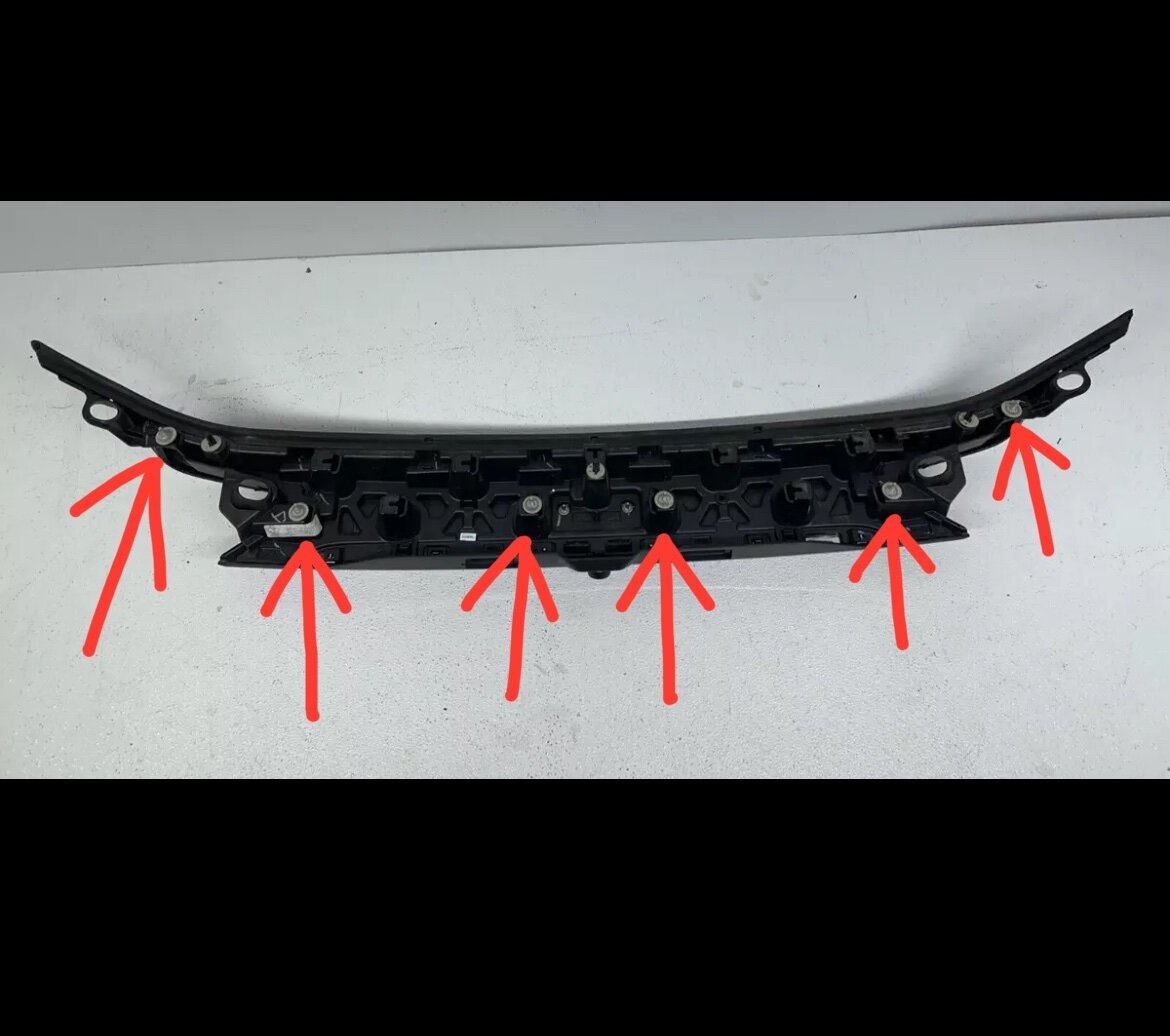
Ok, so I tried to remove the rear camera today. I removed the 2 inner tail lights / reverse lamps. I also removed 6 bolts on the center trim piece, but I just can’t seem to get the center trim piece to come off.
-
Group 65 Battery in 2nd Gen Possible?
Wubster100 replied to omar302's topic in 2015+ Edge & MKX Generation II
FORScan values are not always 100% accurate. Do not change your battery type in FORScan. -
Service advance trac, collision warning not available
Wubster100 replied to pdilow's topic in All Wheel Drive (AWD)
What year? -
Retrofit 360 Camera Into Ford Edge
Wubster100 replied to Wubster100's topic in Accessories & Modifications
Yes, you will need to use FORScan. There will be a change in the BCM to disable the rear camera LIN circuit, because the front and rear camera LIN circuit will connect to the IPMB instead. And some changes in the APIM. -
I am located in the US, and I can’t access the site through my normal browser. For some reason, only Firefox works for me, and it’s an unsecured HTTP site.
-
Thanks. I don’t think the wiring is there anymore, because the HUD has been completely removed on the newer vehicles. The HUD should just simply connect to the canbus network.
-
This doesn’t work on my 2021 Edge, or any of the newer Fusions. I am able to view the the temperature and fan status, but I cannot change it. Has anyone tried it on 2018, 2019, or 2020 Edge?
-
Problem with camera heating
Wubster100 replied to Iroga's topic in Glass, Lenses, Lighting, Mirrors, Sunroof (BAMR), Wipers
Considering that you have no DTCs, an IPMA self test may help you find faults that will trigger a DTC. -
Adding Light to the Trunk
Wubster100 replied to Iroga's topic in Interior, A.C., Heat, Interior Trim
Amazing! Thanks for sharing the details. -
I want to install the red led HUD onto my 2021.
-
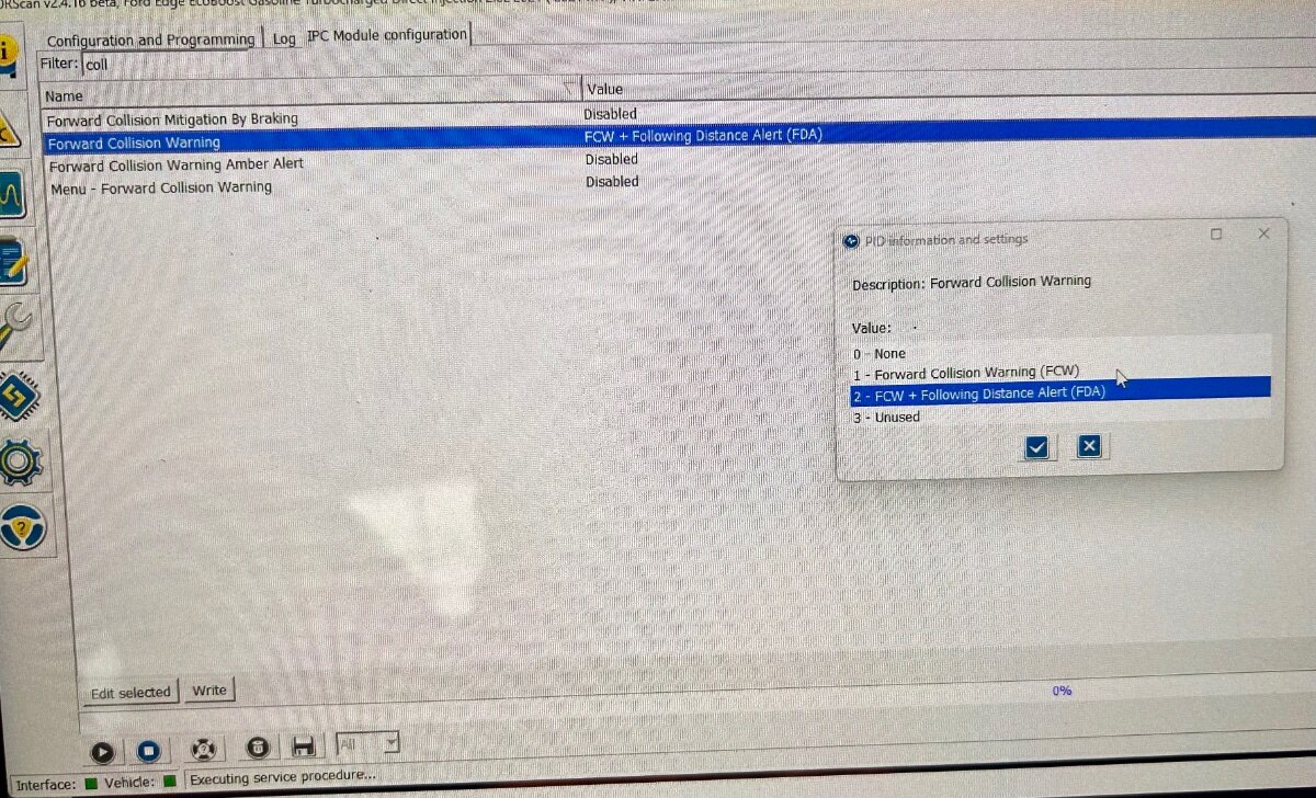
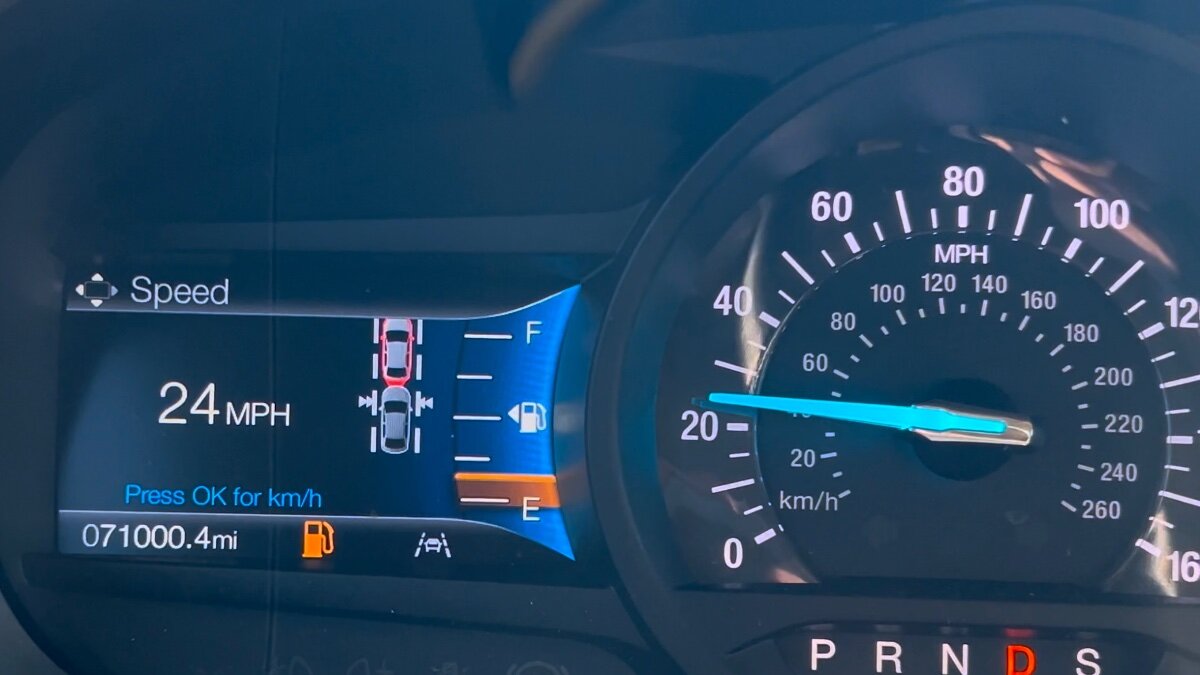
@johnmarkp, @1004ron : I have installed adaptive cruise control, but for a while I never really investigated into the distance indication. The distance indication should work for most IPCs, as long as you have adaptive cruise control. The code is quite simple. Inside of IPC configuration, just change “Forward Collision Warning” from “Forward Collision Warning (FCW)” to “FCW + Following Distance Alert (FDA)”
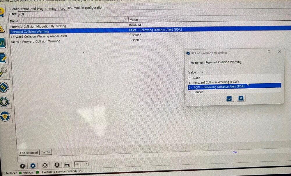
-
Problem with camera heating
Wubster100 replied to Iroga's topic in Glass, Lenses, Lighting, Mirrors, Sunroof (BAMR), Wipers
IPMA Camera Windshield Defrost Heater The camera windshield defrost heater keeps the windshield in front of the IPMA clear of frost and ice. The IPMA uses input from the front camera and the ambient air temperature to turn the camera windshield defrost heater on and off. Voltage and ground is supplied to the heater by the IPMA. The heater may be commanded on if the ambient temperature is below 5°C (41°F ). The IPMA camera windshield defrost heating element is integral to the windshield and can not be serviced without replacing the windshield. Before replacing the IPMA camera heated windshield element or the IPMA for an IPMA camera heated windshield element concern, verify the integrity of the wiring, connectors and terminals on the jumper harness. Camera Windshield Defrost Heater The camera windshield defrost heater is a resistive-type heater grid that is adhered to the inside of the windshield directly in front of the IPMA camera. The camera windshield defrost heater uses a jumper harness between the component and the vehicle harness. Before replacing the camera windshield defrost heater or IPMA for a camera windshield defrost heater concern, verify the integrity of the wiring, connectors and terminals on the jumper harness. -
Problem with camera heating
Wubster100 replied to Iroga's topic in Glass, Lenses, Lighting, Mirrors, Sunroof (BAMR), Wipers
B120C:11 Heater for Windshield Mounted Sensor: Circuit Short To Ground An on-demand and continuous memory DTC that sets in the IPMA if an excessive current draw is detected on the heater output circuit. B120C:13 Heater for Windshield Mounted Sensor: Circuit Open An on-demand and continuous memory DTC that sets in the IPMA if a lower than expected current draw is detected on the heater output circuit. U1000:11 Solid State Driver Protection Activated: Circuit Short To Ground A continuous memory DTC that set in the IPMA when the IPMA has temporarily disabled the camera windshield heater defroster output because an excessive current draw exists (such as a short to ground). The IPMA cannot enable the output driver until the short is corrected. ADDRESS all other IPMA Diagnostic Trouble Codes (DTCs) first. After the cause of the concern is corrected, CLEAR the Diagnostic Trouble Codes (DTCs) and REPEAT the IPMA self-test to enable the output driver -
Problem with camera heating
Wubster100 replied to Iroga's topic in Glass, Lenses, Lighting, Mirrors, Sunroof (BAMR), Wipers
The IPMA supplies voltage and ground to the camera windshield defrost heater. The IPMA uses input from the front camera and the ambient air temperature data from the PCM to command the heater on and off. The heater may be commanded on if the ambient temperature is below 5°C (41°F) -
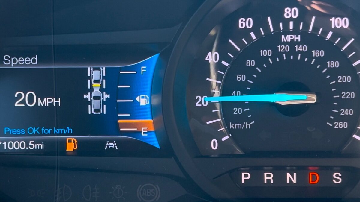
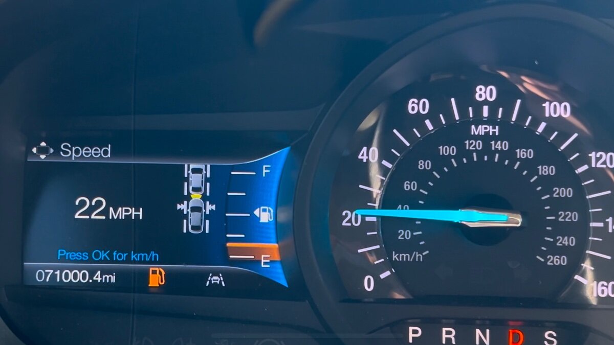
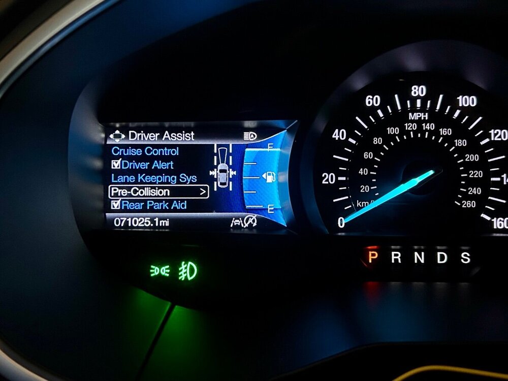
Distance indication is only available for vehicles with adaptive cruise control. The top car icon moves up and down, getting closer or further to your vehicle icon, based on the distance to the vehicle in front of you.
-


-

-
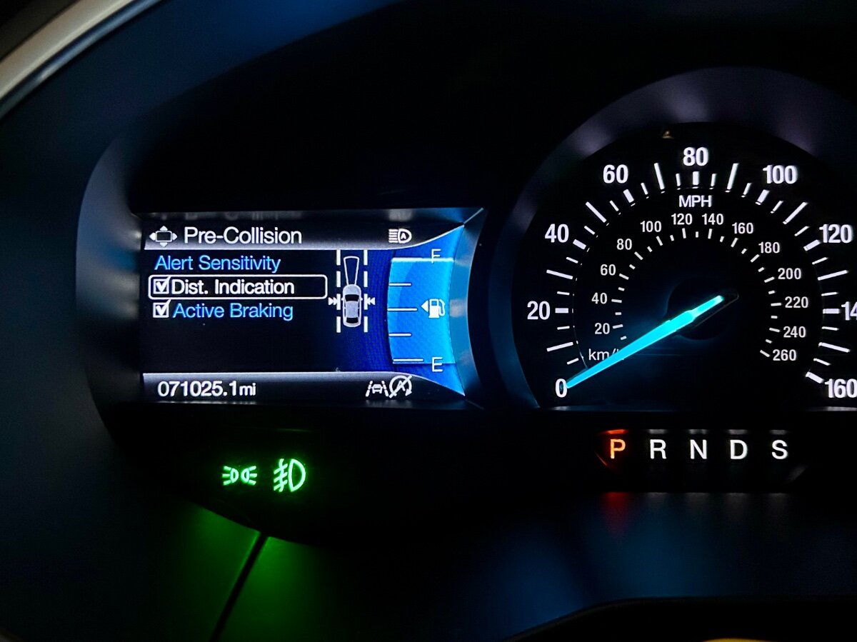
What Is Distance Indication Distance indication displays the gap between your vehicle and the vehicle ahead of you. Note: The graphic does not display if you switch on cruise control or adaptive cruise control. Vehicle Speed System Sensitivity Distance Indicator Color Distance Gap Time Gap 62 mph (100 km/h). Normal. Gray. Greater than 82 ft (25 m). Greater than 0.9 seconds. Yellow. 56–82 ft (17–25 m). 0.6-0.9 seconds. Red. Less than 56 ft (17 m). Less than 0.6 seconds. Switching Distance Indication On and Off To switch the system on or off, use the instrument cluster display: Using the instrument cluster display controls on the steering wheel, select Driver Assist. Select Pre-Collision. Switch Dist. Indication on or off. Distance Indication Indicator The indicator displays the time gap between your vehicle and vehicles traveling in the same direction ahead of you.
-
 I would recommend a SYNC 3 upgrade.
 -
Windshield Replacement
Wubster100 replied to 1004ron's topic in Glass, Lenses, Lighting, Mirrors, Sunroof (BAMR), Wipers
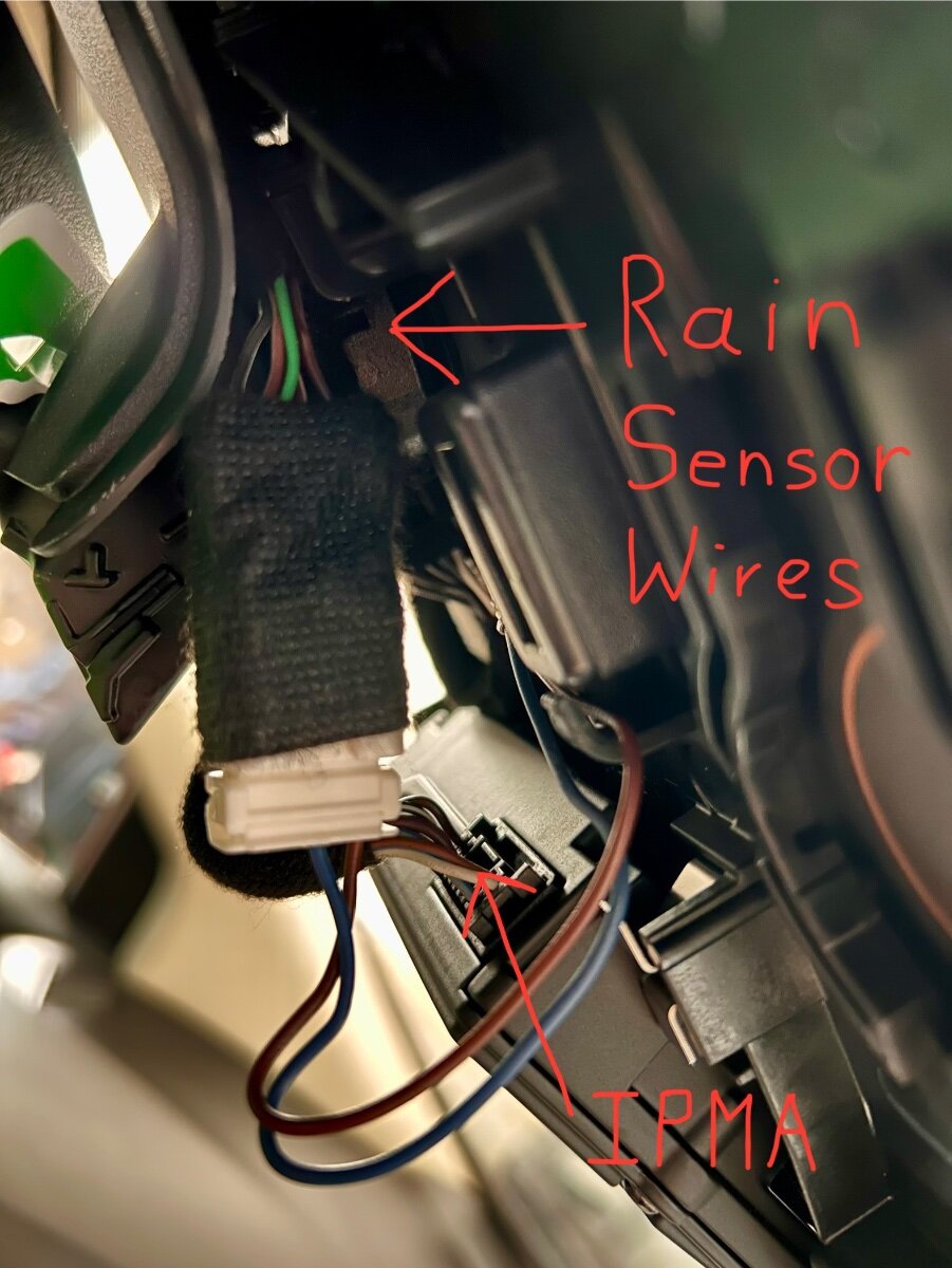
@HazCan you please post the rain sensor wiring diagrams? -
Windshield Replacement
Wubster100 replied to 1004ron's topic in Glass, Lenses, Lighting, Mirrors, Sunroof (BAMR), Wipers
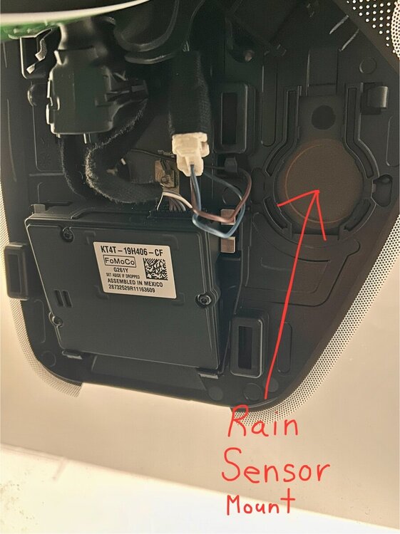
With inspiration from @1004ron replacing their rain sensor, I will attempt to install a rain sensor into my Edge. I always find myself constantly adjusting the wiper speed every time it rains or snows, and it gets annoying if I shut the vehicle off and the wiper’s don’t return to their resting position because they are in the middle of wiping the windshield. I will have to try to sand the black stuff off of the windshield so the sensor can be installed.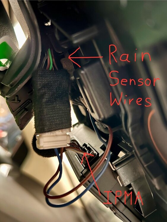
-
Problem with camera heating
Wubster100 replied to Iroga's topic in Glass, Lenses, Lighting, Mirrors, Sunroof (BAMR), Wipers
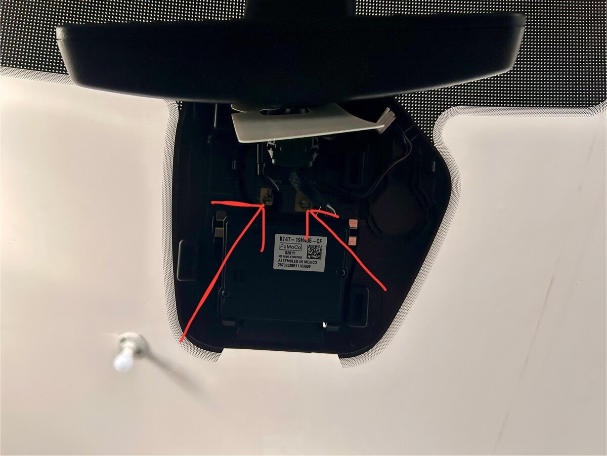
Remove the IPMA cover by pulling down on it, starting from the front of the vehicle. Do you see the IPMB heating element wiring?
-
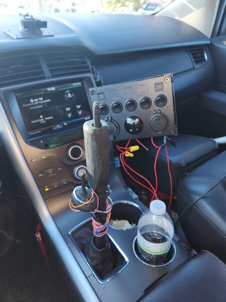
What have you done to/with your Edge/MKX today?
Wubster100 replied to WWWPerfA_ZN0W's topic in Accessories & Modifications
There is nothing broken with my current ABS module. I will be upgrading to a CADS3 ABS module. This new ABS module will support adaptive cruise control (down to 0mph stop and go, instead of down to 12mph), evasive steering assist, lane centering, and auto hold. -
OTA updates have only been a bad experience for me. They seem to be slow to push out new updates. The only reliable way to get updates is to use diagnostic scan tools.
-
Retrofit 360 Camera Into Ford Edge
Wubster100 replied to Wubster100's topic in Accessories & Modifications