Wubster100
-
Posts
648 -
Joined
-
Last visited
-
Days Won
26
Content Type
Profiles
Forums
Gallery
Everything posted by Wubster100
-
 The Trailer Tow Module (TRM) is responsible for managing the trailer's lamps. The TRM determines if a trailer is present by the trailer tow connection (4 pin white, brown, yellow, and green trailer wires). If the TRM thinks that a lamp is connected, then driver assist features such as the rear parking sensors will get disabled, BLIS will get disabled, and trailer sway control will get enabled. Because your Edge is new, you may still have a warranty left on it. Trailer Lamps The TRM supplies voltage to the trailer tow stop/turn lamps when the vehicle stop or turn lamps are commanded on. The TRM supplies voltage to the trailer tow parking lamps when the vehicle parking are commanded on. Field Effect Transistor (FET) Protection The TRM utilizes a Field Effect Transistor (FET) protective circuit strategy for its lamp output circuits. Output loads (current level) are monitored for excessive current (typically short circuits) and are shut down (turns off the voltage or ground provided by the module) when a fault event is detected. A Field Effect Transistor (FET) is a type of transistor that the control module software uses to control and monitor current flow on module outputs. The Field Effect Transistor (FET) protection strategy prevents module damage in the event of excessive current flow. Output loads (current level) are monitored for excessive current draw (typically short circuits). When a fault event is detected the Field Effect Transistor (FET) turns off and a short circuit DTC sets. The module resets the Field Effect Transistor (FET) protection and allows the circuit to function when the fault is corrected or the ignition state is cycled off and then back on. When the excessive circuit load occurs often enough, the module shuts down the output until a repair procedure is carried out. Each Field Effect Transistor (FET) protected circuit has 3 predefined levels of short circuit tolerance based on a module lifetime level of fault events based upon the durability of the Field Effect Transistor (FET). When each level is reached, the DTC associated with the short circuit sets along with DTC U1000:00. These Diagnostic Trouble Codes (DTCs) can be cleared using the module on-demand self-test, then the Clear DTC operation on the scan tool (if the on-demand test shows the fault corrected). The module never resets the fault event counter to zero and continues to advance the fault event counter as short circuit fault events occur. If the number of short circuit fault events reach the third level, then Diagnostic Trouble Codes (DTCs) U1000:00 and U3000:49 set along with the associated short circuit DTC. DTC U3000:49 cannot be cleared and the module must be replaced after the repair
 -
I will also have to bleed the brakes. brake%20system%20bleeding.pdf
-
I have not given up yet. I have an ABS module to install once the weather gets warmer.
-
Power lift gate does not open all the way
Wubster100 replied to edgemaster's topic in Exterior & Body
The latest version of FORScan is 2.3.64 release, 2024-12-16. Or for FORScan Beta users, 2.4.16 beta, 2024-12-17. -
Should I Replace My Water Pump and Thermostat
Wubster100 replied to Perspective's topic in 2.0L EcoBoost
I do not see the water pump listed in the scheduled maintenance. -
Power lift gate does not open all the way
Wubster100 replied to edgemaster's topic in Exterior & Body
Oh, the Power Liftgate Initialization was already posted above. -
Power lift gate does not open all the way
Wubster100 replied to edgemaster's topic in Exterior & Body
I do not know exactly what the Explorer owner means by "initialized the tailgate". Maybe they were referring to Programmable Module Installation (PMI) or something else. I have attached 501-03 - Body Closures - General Procedures - Power Liftgate Initialization If the attached document does not help, you could also try "re-load" the AsBuilt data: 1. Go to configuration and programing 2. Select RGTM Module Configuration (AS BUILT FORMAT) 3. At the bottom of the screen, select "Save All" button. 4. Save the AsBuilt file. 5. At the bottom of the screen, select "Load All" button. 6. Choose the AsBuilt file that you saved in step 4. 7. At the bottom of the screen, select "Write All" button. 8. Reboot the RGTM. Power Liftgate Initialization.pdf -
When the battery is replaced, the BMS must be reset. To reset the BMS without using a diagnostic scan tool: 1. Make sure all windows & doors are closed. 2. Turn ignition switch to on (don't start car). Wait 10 seconds. 3. Flash high beams 5 times using the "flash to pass" stalk on the side of the steering wheel (on/off, on/off, on/off, on/off, on/off). 4. Press brake pedal 3 times in 10 seconds. 5. The battery light on instrument cluster will flash indicating the BMS has been reset. Battery Replacement If the vehicle battery is replaced, it is very important to perform the battery monitoring system reset using the diagnostic scan tool. If the battery monitoring system reset is not carried out, it holds the old battery parameters and time in service counter in memory. Additionally it tells the system the battery is in an aged state and may limit the Electrical Energy Management system functions. Battery State of Charge The Electrical Energy Management system monitors the battery current flow and voltage to determine the battery state of charge. During the drive cycle the Electrical Energy Management system software monitors the charge and discharge current and increases the state of charge during charging, and decreasing it during discharge. During rest periods (key off with no electrical loads) when the vehicle enters sleep mode, the battery voltage is sampled to calibrate the state of charge. The sensor automatically executes this calibration anytime the vehicle enters sleep mode and when the total vehicle current draw is below 300mA. It takes 4 to 6 hours in the sleep mode to calibrate the battery state of charge to high accuracy. If the system draw does not allow the battery state of charge calibration over the previous 7 to 10 days the state of charge quality factor changes to flag this and some Electrical Energy Management system functions, which rely on the accuracy of the battery state of charge, may be temporarily turned off until a calibration takes place. Battery Monitoring Sensor NOTICE: Unless the battery is being replaced, DO NOT reset the battery monitoring system using the diagnostic scan tool. This reset is reserved for new battery installation only. This reset will clear the learned battery data, the battery time in service, and will affect the aging algorithm parameters, which have been learned since the installation of the battery. The battery monitoring sensor is integrated with the negative battery terminal clamp and cable assembly, which provides a ground to the sensor. The battery monitoring sensor measures voltage, current, and temperature of the battery and uses these inputs to calculate the battery condition. The sensor transmits this information through the LIN circuit to the BCM. The battery monitoring sensor has a 2-pin connector providing battery voltage and LIN connections.
-
Cruise Control alarm bell 2024 Edge
Wubster100 replied to mooseboy's topic in Interior, A.C., Heat, Interior Trim
There are multiple driver assist features for the Edge. Adaptive cruise control is used on highways and it will automatically brake / keep a distance to the vehicle in front of you. Lane centering is only able to be activated in conjunction with adaptive cruise control. Lane centering keeps your vehicle in the center of the painted road lines. Lane keep assist is available anytime at speeds above ~35mph. If your vehicle gets close to the painted lane line, the steering wheel will be nudged in the opposite direction to help keep you inside your lane. The 2024 Edge Owner’s Manual describes these driver assist features in detail: https://www.fordservicecontent.com/Ford_Content/Catalog/owner_information/2024_Ford_Edge_Owners_Manual_version_1_om_EN-US.pdf -
Retrofit 360 Camera Into Ford Edge
Wubster100 replied to Wubster100's topic in Accessories & Modifications
@Haz, Do any Ford Edge workshop manuals or wiring resources mention anything else about a 360 camera system? I do not know of any Ford Edges that came with a 360 camera system. -
Retrofit 360 Camera Into Ford Edge
Wubster100 replied to Wubster100's topic in Accessories & Modifications
Yes, it is definitely for the HCM. I don't have the fancy headlights. If necessary, I may be able to use the HCM connector to allow the new IPMB to connect to the HS2-CAN network. -
Retrofit 360 Camera Into Ford Edge
Wubster100 replied to Wubster100's topic in Accessories & Modifications
What is "413-13B Parking Aid - Vehicles With: Parking Aid Camera" from the 2022-2024 Edge WSM? It goes over the procedure to align the 360 camera system, but why does it exist if the Edge never had a 360 camera system? -
Retrofit 360 Camera Into Ford Edge
Wubster100 replied to Wubster100's topic in Accessories & Modifications
@Haz, can I also get the connector pinouts and locations for the Edge: Without split view: C408, C411, C213 With split view: C213, C212, C408, C411, C139, C133 The connectors that are in bold are listed twice. -
Retrofit 360 Camera Into Ford Edge
Wubster100 replied to Wubster100's topic in Accessories & Modifications
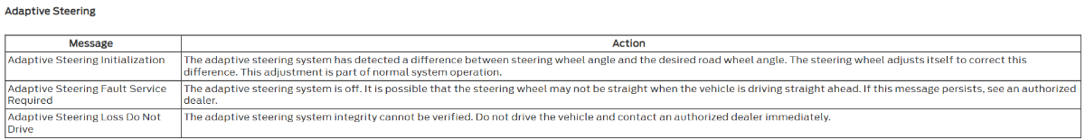
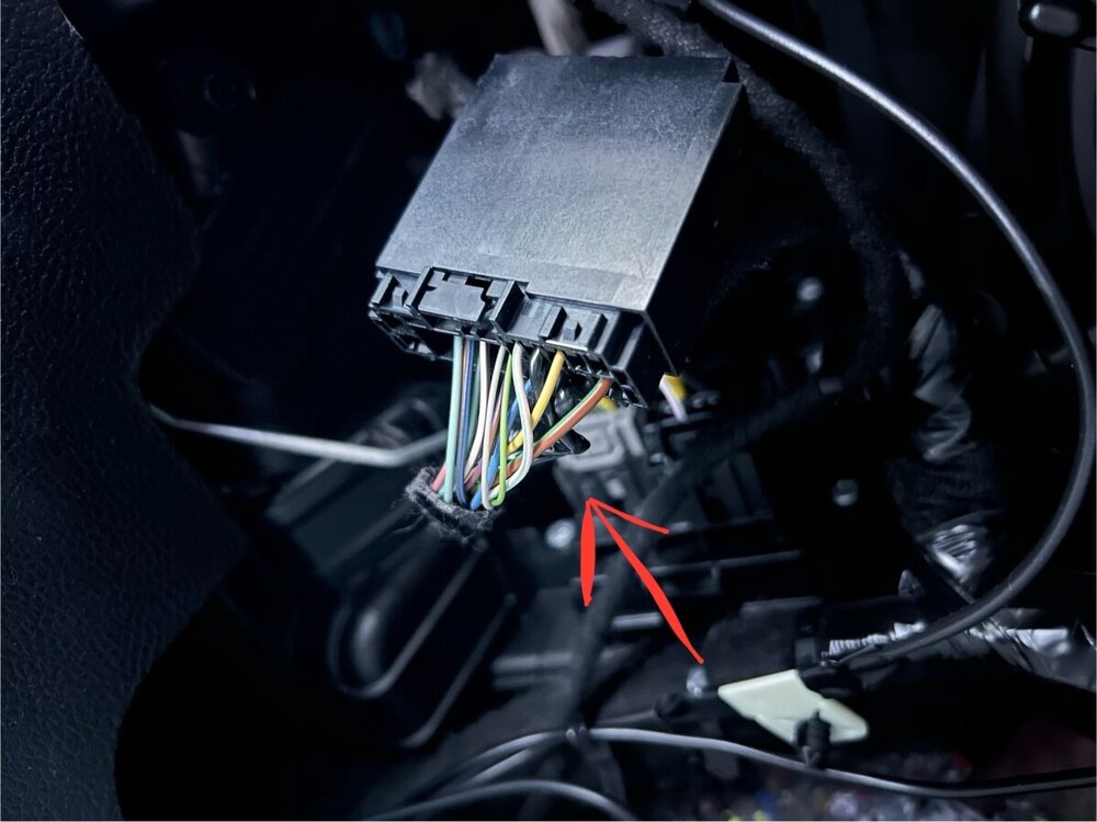
I searched around the glove box area, and I was able to find one unused connector. This connector is located underneath the ac blower fan. I am not sure if it is some kind of splice or what it is used for.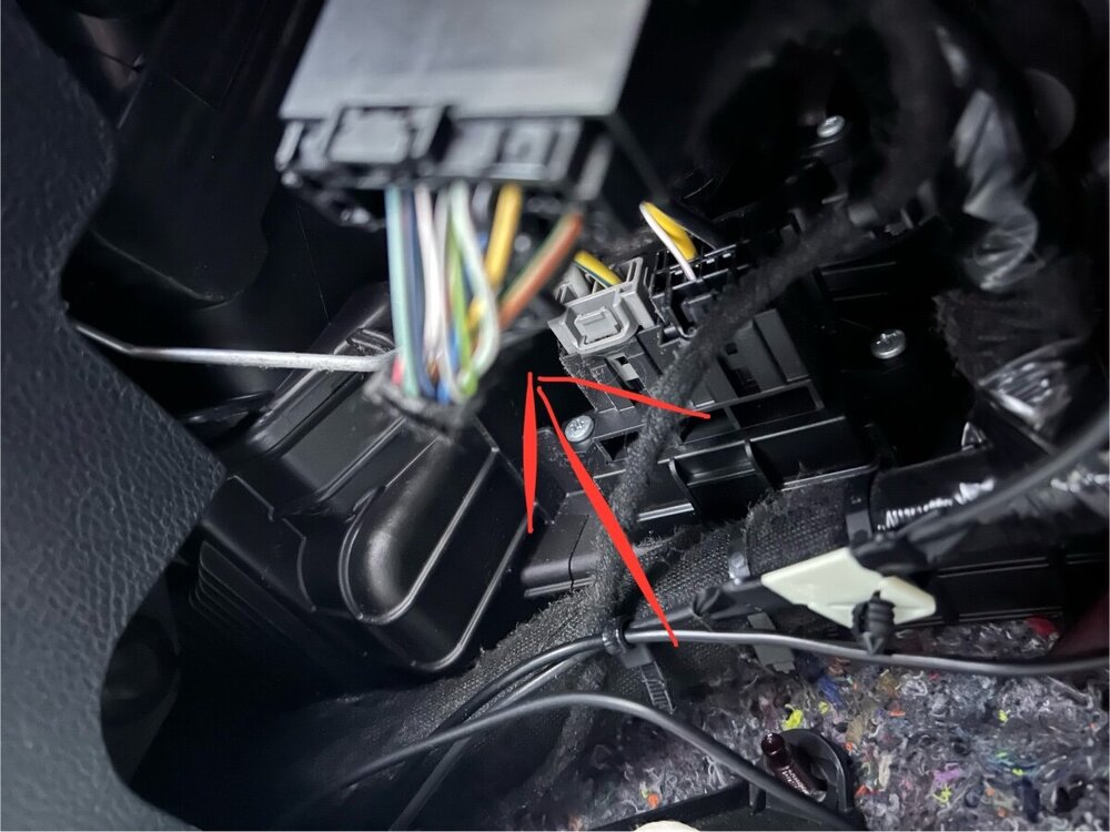

-
Are you able to scan for DTCs?
-
Help - Code: C1039:94-0A Active Front Steering (AFS) Lock
Wubster100 replied to al303's topic in Brakes, Chassis & Suspension
Unfortunately I was unable to locate the diagnosis and testing for the power steering. -
Help - Code: C1039:94-0A Active Front Steering (AFS) Lock
Wubster100 replied to al303's topic in Brakes, Chassis & Suspension
Power Steering - System Operation and Component Description.pdf -
Help - Code: C1039:94-0A Active Front Steering (AFS) Lock
Wubster100 replied to al303's topic in Brakes, Chassis & Suspension
Information Messages - Adaptive Steering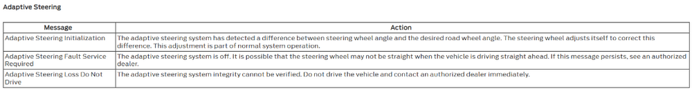
-
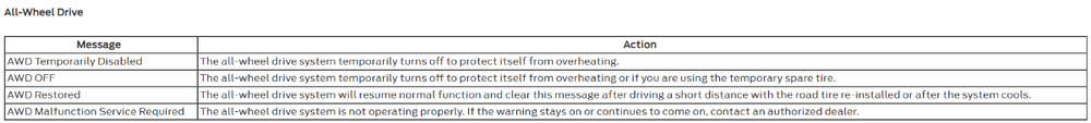
Heat Protection - Power Transfer Unit During excessive use or when towing a trailer, the AWD system may implement a heat protection mode to protect the power transfer unit from damage. Using the input from power transfer unit temperature sensors, the AWD module performs calculations to determine the demand for use of the heat protection mode. The AWD system then reduces the commanded torque being applied by the RDU to the rear axles, and/or disconnects the power transfer unit dog clutch. Once the maximum temperature limit is reached, AWD mode only is commanded and the AWD temporarily disabled or AWD OFF message is displayed in the IPC. Heat Protection - Rear Drive Unit (RDU) During aggressive on road driving, the AWD system may implement a heat protection mode to protect the RDU clutch from damage due to overheating. On variants not fitted with power transfer unit or RDU temperature sensors, the AWD module performs calculations to determine the need for the heat protection mode. If the AWD system detects an overheat condition, it enters a locked mode. If the heat in the RDU continues to rise once in the locked mode, the AWD module disables the torque commands to RDU. This condition may be indicated by an AWD Temporarily Disabled message in the message center. To resume normal operation, stop the vehicle in a safe location and turn the engine off for at least 10 minutes. After the engine is restarted and the AWD system has adequately cooled down, the AWD Temporarily Disabled message turns off and normal AWD operation returns. In the event the engine is turned off during the stop, the AWD Temporarily Disabled message turns off when the system cools. Normal AWD operation returns once the message center displays AWD Restored. Information Messages - AWD
-
Good to know that it is possible. I don't think I will enable it because usually I just have my fog lights on anyways.
-
Retrofit 360 Camera Into Ford Edge
Wubster100 replied to Wubster100's topic in Accessories & Modifications
Once again, @Haz steps up, never failing to amaze! -
Retrofit 360 Camera Into Ford Edge
Wubster100 replied to Wubster100's topic in Accessories & Modifications
A rear 180 camera would definitely be useful. -
Hello everyone, I will be attempting to retrofit the 360 camera system similar to the Lincoln MKX/Nautilus. The Edge only has the option for a front 180 camera. @HazI am requesting the following information: 2021-2024 Edge APIM wiring diagram 2021-2024 Edge IPMB wiring diagram 2021-2024 Edge front + rear camera wiring diagrams (with and without IPMB) 2021-2024 Edge camera button wiring diagram 2016-2020 MKX/Nautilus IPMB connector pinout 2016-2020 MKX/Nautilus camera button wiring diagram
-
What have you done to/with your Edge/MKX today?
Wubster100 replied to WWWPerfA_ZN0W's topic in Accessories & Modifications
https://www.fordedgeforum.com/uploads/monthly_2025_01/20250104_112217.mp4.d242a292e24c20668d3c2c47f41c3d34.mp4 -
Weird acting rear light…
Wubster100 replied to FLvet85's topic in Glass, Lenses, Lighting, Mirrors, Sunroof (BAMR), Wipers
Field Effect Transistor (FET) Protection The BCM utilizes an Field Effect Transistor (FET) protective circuit strategy for many of its outputs, for example, lamp output circuits. Output loads (current level) are monitored for excessive current (typically short circuits) and are shut down (turns off the voltage or ground provided by the module) when a fault event is detected. A Field Effect Transistor (FET) is a type of transistor that the control module software uses to control and monitor current flow on module outputs. The Field Effect Transistor (FET) protection strategy prevents module damage in the event of excessive current flow. Output loads (current level) are monitored for excessive current draw (typically short circuits). When a fault event is detected the Field Effect Transistor (FET) turns off and a short circuit DTC sets. The module resets the Field Effect Transistor (FET) protection and allows the circuit to function when the fault is corrected or the ignition state is cycled off and then back on. When the excessive circuit load occurs often enough, the module shuts down the output until a repair procedure is carried out. Each Field Effect Transistor (FET) protected circuit has 3 predefined levels of short circuit tolerance based on a module lifetime level of fault events based upon the durability of the Field Effect Transistor (FET). If the total tolerance level is determined to be 600 fault events, the 3 predefined levels would be 200, 400 and 600 fault events. When each level is reached, the DTC associated with the short circuit sets along with DTC U1000:00. These Diagnostic Trouble Codes (DTCs) can be cleared using the module on-demand self-test, then the Clear DTC operation on the scan tool (if the on-demand test shows the fault corrected). The module never resets the fault event counter to zero and continues to advance the fault event counter as short circuit fault events occur. If the number of short circuit fault events reach the third level, then Diagnostic Trouble Codes (DTCs) U1000:00 and U3000:49 set along with the associated short circuit DTC . DTC U3000:49 cannot be cleared and the module must be replaced after the repair.