


Wubster100
-
Posts
648 -
Joined
-
Last visited
-
Days Won
26
Content Type
Profiles
Forums
Gallery
Everything posted by Wubster100
-

What have you done to/with your Edge/MKX today?
Wubster100 replied to WWWPerfA_ZN0W's topic in Accessories & Modifications
-
Welcome to the forum @xtraorange. Do you see a seat module underneath the seat?
-
FordPass no longer updating location while moving
Wubster100 replied to dabangsta's topic in Audio, Backup, Navigation & SYNC
Ensure the app is updated to version 5.9.0 You can now add service history information to your account to keep all your maintenance records in one place. Theft alerts now include a map view, history, and alert preferences. With a Security Package subscription, you can remotely lock down eligible vehicles to stop them from starting without permission. We've added real-time updates to your vehicle data, giving you access to the most current location information. -
Ford cannot do any programming. You must program it yourself using FORScan. The face plate with the heated seats buttons may not even be required if you only want to control the heated seats through the touchscreen. The heated seats are controlled over the network, through the seat modules.
-
2013 ABS module/HCU Programming
Wubster100 replied to John 2013 Edge's topic in Brakes, Chassis & Suspension
If it were me, I would use a third party software, FORScan, to reprogram the ABS module. -
2013 ABS module/HCU Programming
Wubster100 replied to John 2013 Edge's topic in Brakes, Chassis & Suspension
FJDS provides module reprogramming software that covers 1996 to select 2018 Ford, Lincoln and Mercury module reprogramming functions, plus complete dealership level diagnostic software for all 2018 to present Ford and Lincoln vehicles. FJDS is designed for use with J2534 compatible Vehicle Communications Interfaces (VCI) including Ford diagnostic hardware (VCM II, or VCMM). The FJDS software license includes time based access to the FJDS software, software updates and calibration files. The following vehicles are supported by FDRS 2018+ Expediion/Navigator 2018+ Ecosport 2019+ Ranger 2020+ Transit 2019+ Transit Connect 2020+ Explorer/Aviator 2020+ Super Duty 2020+ Escape/Corsair 2021+ F-150 2021+ Edge/Nautilus 2021+ Mach-E All other vehicles are supported by IDS/FJDS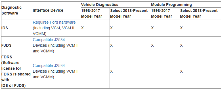
-
Welcome to the forum @kcrews10! It is possible to install a SYNC 3 system and heated seats. I would assume that you have the small 4.2" screen. However, it is not plug and play. Programming is required for both the radio upgrade and heated seats.
-
Rear Seat Cushion Loose 2015-2024
Wubster100 replied to Wubster100's topic in Interior, A.C., Heat, Interior Trim
Welcome to the forum @Mbry2024! I never bothered to get new clips, so the seat cushion is still a bit loose. Have you tried looking at your cushion locking tabs / clips? Do you still have a warranty left on your 2023? -
Has anyone tried the LV fluid instead of ULV?
-
There is a trailer tow module for the trailer lights and trailer sway control.
-
The photos in the video are AI generated. There will not be a 2025 Ford Edge. However, there is a different vehicle, the Ford Edge L, which is larger and avalible in China.
-
Wow… looking at the 2010 AsBuilt data versus modern Fords, there is a lot more data!
-
Now, someone please tell me if 2015-2018 tail lights will fit 2019-2024
-
Heated and Cooled Seats
Wubster100 replied to Wedgeamatic's topic in Interior, A.C., Heat, Interior Trim
No, there is only 1 module for each seat. The part numbers are from two differing generations of the Edge. Gen 2 2015-2018, and Gen 2.5 2019-2024 -
Use resistors in place of the missing bulb, or if the turn signals are controlled by a microcontroller in the BCM, then you could use FORScan to fix it.
-
Heated and Cooled Seats
Wubster100 replied to Wedgeamatic's topic in Interior, A.C., Heat, Interior Trim
Seat Heater Control Module GU5Z14C724A Edge 2016-2018 Seat Memory Control Module Unit GU5Z14C708BP Edge 2019-2024 -
Attention - there's an uptick in accounts being hacked
Wubster100 replied to 1004ron's topic in Forum Help & Site Suggestions
It doesn't look like there are any 2 factor authentication methods available either. -
What are the part numbers for all of the parking sensors retainers? They look similar to the image below, and the plastic retainer gets “welded” to the plastic panels of the car.

-
Group 65 Battery in 2nd Gen Possible?
Wubster100 replied to omar302's topic in 2015+ Edge & MKX Generation II
If you did not upgrade to a larger battery size or different battery chemistry, then there are no changes to be made except for resetting the BMS. -
Does anyone have any tips on how to ensure the vehicle is level while the front wheel is removed? I can park on a level garage floor.
-
2022 Edge ST rear fog light
Wubster100 replied to WilkiST's topic in Glass, Lenses, Lighting, Mirrors, Sunroof (BAMR), Wipers
@WilkiSTNow that you are importing your vehicle from the US to another country, have you considered enabling the emergency flashing brake lights? This feature is common in Europe now. -
Group 65 Battery in 2nd Gen Possible?
Wubster100 replied to omar302's topic in 2015+ Edge & MKX Generation II
I currently have the original H6 AGM battery. A few months ago, auto start stop worked for a few days after I drove for about 8 hours on the highway.


