omar302 Posted January 29, 2023 Report Share Posted January 29, 2023 31 minutes ago, 1STSFG said: A close look at factory HID headlight assembly shows the HID low/high beam with igniter AND a inboard halogen bulb that appears to have no function in the OE HID application. In the 16 sport anyway. I assume the assembly was built for the majority of non HID options ordered/built? You are quoting a post from 2017! 2015-2018 Edges with factory HID have H15 bulbs on the inboard that function as DRL lights only. H15 is a dual filament bulb designed as DRL for the low wattage filament and High beams for the high wattage filament, the Edge (with factory HID) only utilize's the low voltage filament, DRL. There is no wiring connected to the high wattage filament. 1 Quote Link to comment Share on other sites More sharing options...
1STSFG Posted January 29, 2023 Report Share Posted January 29, 2023 Interesting that ours don’t light on any setting........ Quote Link to comment Share on other sites More sharing options...
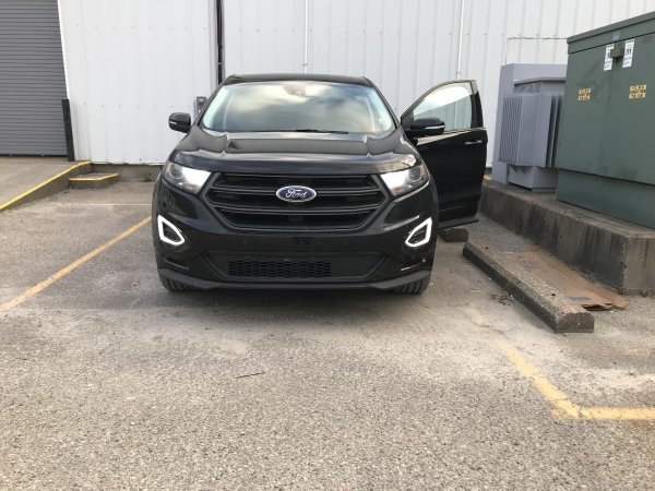
1STSFG Posted January 29, 2023 Report Share Posted January 29, 2023 (edited) Two HID’s and two amber lights in DRL. Edited January 29, 2023 by 1STSFG Quote Link to comment Share on other sites More sharing options...
omar302 Posted January 29, 2023 Report Share Posted January 29, 2023 In a US Edge, to get the DRL to turn on, you have to have them enabled in the settings menu in the cluster, headlight switch should on auto, and transmission shift lever out of Park. 1 Quote Link to comment Share on other sites More sharing options...
Summers22 Posted February 22, 2023 Report Share Posted February 22, 2023 So is it okay to run H11 HID in the low beam spot if DRL is disabled through the cluster? Quote Link to comment Share on other sites More sharing options...
MetalAnon Posted March 3, 2023 Report Share Posted March 3, 2023 On 2/22/2023 at 8:09 AM, Summers22 said: So is it okay to run H11 HID in the low beam spot if DRL is disabled through the cluster? Disabling DRLs through the cluster only affects the inboard (high beam position) and should not have any influence on the outboard bulb position. At least on our 2016 Sport with factory HID projectors, that’s how it works. Quote Link to comment Share on other sites More sharing options...
dabangsta Posted March 3, 2023 Report Share Posted March 3, 2023 What is used as the DRL differs depending on what type of headlight (halogen or HID) you have. If you have halogen then it is the low beam, if you have HID it is the dedicated H15 bulb. 1 Quote Link to comment Share on other sites More sharing options...
Haz Posted March 3, 2023 Report Share Posted March 3, 2023 From the 2016 Edge Workshop Manual... Moving your device cursor over capitalized acronyms should yield an onscreen full-word description. DRL System Diagram Network Message Chart BCM Network Input Messages Broadcast Message Originating Module Message Purpose Gear position PCM Indicates the GSM request to the BCM . When the GSM has selected any position other than park, the BCM activates the DRL . DRL For the halogen headlamp system, the DRL system utilizes the existing circuitry and components from the headlamp low beam system. The DRL system operates the low beam headlamps at a reduced intensity. For the High Intensity Discharge (HID) headlamp system, DRL system utilizes a halogen bulb in the headlamp assembly. The BCM monitors the ignition status, the headlamp switch and autolamp status. There are two types of DRL . Conventional (where it is required) and configurable. When equipped with conventional DRL , the DRL are active in any headlamp switch position except the HEADLAMPS position. When equipped with configurable DRL , the DRL may be enabled through the IPC message center. When enabled, the DRL are active only in the AUTOLAMPS headlamp position. When autolamps request the headlamps on, the DRL are de-activated. The DRL are activated when the following conditions are met: the ignition is in run the headlamps have not been turned on by the autolamp system or the headlamp switch the transmission is not in park When a turn signal is active, the corresponding daytime running lamp will turn off. Once the turn signal is deactivated, the daytime running lamp returns to normal operation. When the transmission is in not in PARK, the PCM sends a message over the HS-CAN1 to the BCM indicating the transmission is not in PARK. The BCM also provides Field Effect Transistor (FET) protection of the exterior lamps switched voltage and DRL output circuits. When an excessive current draw is detected, the BCM disables the affected circuit driver. Field Effect Transistor (FET) Protection The BCM utilizes an Field Effect Transistor (FET) protective circuit strategy for many of its outputs, for example, lamp output circuits. Output loads (current level) are monitored for excessive current (typically short circuits) and are shut down (turns off the voltage or ground provided by the module) when a fault event is detected. A Field Effect Transistor (FET) is a type of transistor that the control module software uses to control and monitor current flow on module outputs. The Field Effect Transistor (FET) protection strategy prevents module damage in the event of excessive current flow. Output loads (current level) are monitored for excessive current draw (typically short circuits). When a fault event is detected the Field Effect Transistor (FET) turns off and a short circuit DTC sets. The module resets the Field Effect Transistor (FET) protection and allows the circuit to function when the fault is corrected or the ignition state is cycled off and then back on. When the excessive circuit load occurs often enough, the module shuts down the output until a repair procedure is carried out. Each Field Effect Transistor (FET) protected circuit has 3 predefined levels of short circuit tolerance based on a module lifetime level of fault events based upon the durability of the Field Effect Transistor (FET). If the total tolerance level is determined to be 600 fault events, the 3 predefined levels would be 200, 400 and 600 fault events. When each level is reached, the DTC associated with the short circuit sets along with DTC U1000:00. These Diagnostic Trouble Codes (DTCs) can be cleared using the module on-demand self-test, then the Clear DTC operation on the scan tool (if the on-demand test shows the fault corrected). The module never resets the fault event counter to zero and continues to advance the fault event counter as short circuit fault events occur. If the number of short circuit fault events reach the third level, then Diagnostic Trouble Codes (DTCs) U1000:00 and U3000:49 set along with the associated short circuit DTC . DTC U3000:49 cannot be cleared and the module must be replaced after the repair. Headlamp Assembly Wiring Diagram - Left Hand Headlamp Assembly Wiring Diagram - Right Hand Good luck! 4 Quote Link to comment Share on other sites More sharing options...
MetalAnon Posted December 1, 2023 Report Share Posted December 1, 2023 GREAT post @Haz! It's been awhile since I checked on this thread, but I have been thinking about an idea in the interim that I have not seen anyone else bring up... and the workshop manual informations piqued my interest further, should be quite helpful. Specifically, I am seeking to make use of the DRL positions (inboard spots in the housing) since I personally disable the DRLs and they are wasting space. I'm looking to make the those inboard positions function as and with the high beams, in addition to the (low/high shutter) high beams in the outboard positions. So that when the high beams are activated, our Edge would have four bulbs to throw an obscene amount of forward light down the road. So since I have swapped out the factory D3S HID bulbs to aftermarket LED D3S bulbs which simply plug n play with the factory HID ballasts. The shutter the HIDs utilize also made the swap easier and the LEDs work supremely and considerably brighter than the OE HID bulbs without blinding oncoming drivers. I hadn't considered Ford's use of the Field Effect Transistor (FET) in the BCM, so ironing that out may require additional brain power but I'll cross that bridge once im there. So the idea is to splice a pigtail into the HID high beam wiring and install it in the DRL position but I haven't examined it in detail yet. I just wanted to post something about it while I was here and had it on my mind. Damn life has been hectic lately and I have been known to forget things before I get them down on a bar napkin. Should prolly start another post for such a project but I thought this thread would be a good a place as any for sharing. Ok now I gotta get some sleep. Quote Link to comment Share on other sites More sharing options...
Big-ted Posted December 4, 2023 Report Share Posted December 4, 2023 (edited) First post. Have already gotten a ton of useful info from this site in doing a factory hitch install on my 2016 Edge sport, so thanks. Bought the vehicle in the Summer and am very pleased so far. Just slightly disappointed in the headlights. I'm in Canada, in BC, where it's dark and wet 11.5 months a year and I'm required to keep the DRL enabled. I'm also an optical engineer, so will 100% attest to the fact that dropping an LED emitter into a housing/optic intended for a halogen bulb without any consideration for the different source profiles is unlikely to give good results... What's the go-to setup to get more usable light out of the stock reflectors in the dimmed setting? Sounds like the vehicle is using H11 bulbs for this function, and going to an H9 is one option, but will result in greater light output for the DRLs also? Don't think I'm super concerned about that since glare is less of an issue during the day anyway? Edited December 4, 2023 by Big-ted Quote Link to comment Share on other sites More sharing options...
Sunnyorlando Posted February 6 Report Share Posted February 6 I just posted this update in another headlight thread. May not work with 2016, but sure does with at least the '17 and on with HID. BTW - good quality LED bulbs have come a long ways, and with the newer ones having the LEDs positions line up with the respective halogen elements, they do work pretty good to align with the reflectors. Quote Link to comment Share on other sites More sharing options...


Recommended Posts
Join the conversation
You can post now and register later. If you have an account, sign in now to post with your account.
Note: Your post will require moderator approval before it will be visible.