Haz
-
Posts
1,568 -
Joined
-
Last visited
-
Days Won
439
Content Type
Profiles
Forums
Gallery
Everything posted by Haz
-
@garycrist: Fluid specifications and related procedures from 2022-2024 Edge Workshop Manual are attached below as PDF documents... Good luck! Specifications - Rear Drive Axle-Differential - 2022-2024 Edge.pdf Differential Draining and Filling - Rear Drive Axle-Differential - 2022-2024 Edge.pdf Differential Fluid Level Check - Rear Drive Axle-Differential - 2022-2024 Edge.pdf Specifications - Power Transfer Unit - 2.7L EcoBoost - 2022-2024 Edge.pdf Power Transfer Unit Draining and Filling - Power Transfer Unit - 2.7L EcoBoost - 2022-2024 Edge.pdf Power Transfer Unit Fluid Level Check - Power Transfer Unit - 2.7L EcoBoost - 2022-2024 Edge.pdf
-
A survey of twenty-six 2020 Edge Titanium 2.0L EcoBoost vehicles offered for sale online, yielded nine listings with engine compartment photos... Good luck!
-
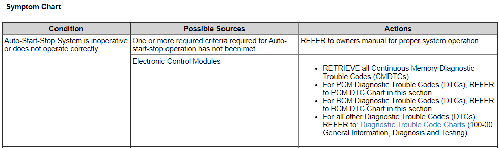
From the 2020 Workshop Manual... Placing your device cursor over underlined acronyms may yield popup full-words descriptions of the acronyms. Auto-Start-Stop System The Auto-start-stop system helps reduce fuel consumption by automatically shutting off the vehicle’s engine while the vehicle is at a complete stop and restarting the engine when the brake pedal is released. The system can be disabled through the auto-start-stop control switch on the instrument panel centerstack. The Auto-start-stop system is automatically enabled whenever the ignition is turned on. The engine automatically restarts when: the brake pedal is released. the Auto-start-stop system is disabled through the auto-start-stop control switch on the instrument panel centerstack. the battery has a low state of charge. it is necessary to maintain interior comfort. the blower fan speed is increased or the climate control temperature is changed. an electrical accessory is turned on or plugged in. there is low brake vacuum. The Auto-start-stop system may not turn the engine off under these conditions: the HVAC system is in A/C, heat or defrost modes. the rear defroster is on. the battery has a low state of charge. the battery temperature is below 5°C (41°F) or above 60°C (140°F). the engine temperature is below 46°C (115°F). the engine temperature is below 60°C (140°F) and the HVAC system is in heat mode. the gear selector is not in Drive or Sport Mode. the steering wheel is turned rapidly or is at a sharp angle. vehicle speed of greater than 4 km/h (2.5 mph) for more than 2 seconds has not occurred. the vehicle is on a steep road grade. elevation is approximately above 3,048 meters (10,000 feet). Electrical Energy Management System This vehicle is equipped with an Electrical Energy Management system which manages battery charging and monitors the battery state of charge. The Electrical Energy Management system also utilizes a load shed strategy to help control discharge of the battery and prevent, when possible, an excessively low battery state of charge. The BCM uses a battery monitoring sensor to monitor the battery state of charge. To maintain correct operation of the load shed system, any electrical devices or equipment must be grounded to the chassis ground and not the negative battery terminal. A connection to the negative battery terminal causes an inaccurate measurement of the battery state of charge and incorrect load shed system operation due to the current being used bypassing the battery monitoring sensor. Refer to the Battery Monitoring Sensor component description in this section. Battery State of Charge The Electrical Energy Management system monitors the battery current flow and voltage to determine the battery state of charge. During the drive cycle the Electrical Energy Management system software monitors the charge and discharge current and increases the state of charge during charging, and decreasing it during discharge. During rest periods (key off with no electrical loads) when the vehicle enters sleep mode, the battery voltage is sampled to calibrate the state of charge. The sensor automatically executes this calibration anytime the vehicle enters sleep mode and when the total vehicle current draw is below 300mA. It takes 4 to 6 hours in the sleep mode to calibrate the battery state of charge to high accuracy. If the system draw does not allow the battery state of charge calibration over the previous 7 to 10 days the state of charge quality factor changes to flag this and some Electrical Energy Management system functions, which rely on the accuracy of the battery state of charge, may be temporarily turned off until a calibration takes place. NOTE: Any devices left attached to the power socket that draw in excess of 200mA (or less depending on other battery loads), prevents a battery monitoring sensor from calibrating the battery state of charge. Battery Monitoring Sensor NOTICE: Unless the battery is being replaced, DO NOT reset the battery monitoring system using the diagnostic scan tool. This reset is reserved for new battery installation only. This reset will clear the learned battery data, the battery time in service, and will affect the aging algorithm parameters, which have been learned since the installation of the battery. The battery monitoring sensor is integrated with the negative battery terminal clamp and cable assembly, which provides a ground to the sensor. The battery monitoring sensor measures voltage, current, and temperature of the battery and uses these inputs to calculate the battery condition. The sensor transmits this information through the LIN circuit to the BCM . The battery monitoring sensor has a 2-pin connector providing battery voltage and LIN connections. The battery monitoring sensor is an input to the Electrical Energy Management system software. If the sensor malfunctions due to wiring issues or failure, a DTC sets. In most cases the Electrical Energy Management system functions are turned off until the sensor operation is restored. Attached below as PDF documents are Workshop Manual sections from which the above information was obtained, along with a section on Battery Load Shed strategies, which are based upon State of Charge (SOC) conditions. Good luck! Starting System - System Operation and Component Description - 2020 Edge Workshop Manual.pdf Charging System - 2.0L EcoBoost - System Operation and Component Description - 2020 Edge Workshop Manual.pdf Battery Load Shed - Operation and Description - 2020 Edge Workshop Manual.pdf
-
Welcome to the Forum @Gilmore! This is not a Recall. Special Service Messages provide information to professional technicians about recommended Service actions when a vehicle exhibits specific symptoms. In this case, if the described AWD vehicle is exhibiting slow speed rear-end chatter or shudder while turning, then fluid contamination may likely be the cause, and changing the RDU fluid should be the technician's first-step toward correcting the issue. No suggestion is made that contaminated fluid was installed during assembly. The Workshop Manual citation informs technicians about a yellowish or greenish fluid coloration that may be visually evident on low mileage vehicles, which is attributable to the gear mesh marking compound -- with no recommendation for a fluid change. The Workshop Manual does recommend fluid change when milky fluid is found, which is indicative of water contamination. The Special Service Message provides another reason for fluid change -- a vehicle's behavioral issue of rear end chatter/shutter on turns. Good luck!
-
Welcome to the Forum @jlcinga! Contact your dealership's Service department and ask if their Mobile Service unit can retrieve your Nautilus' Keypad Code at your home or place of business. Otherwise, request Lincoln Pickup & Delivery to have your Nautilus' Keypad Code retrieved by a Service technician at the dealership. Good luck!
-
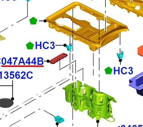
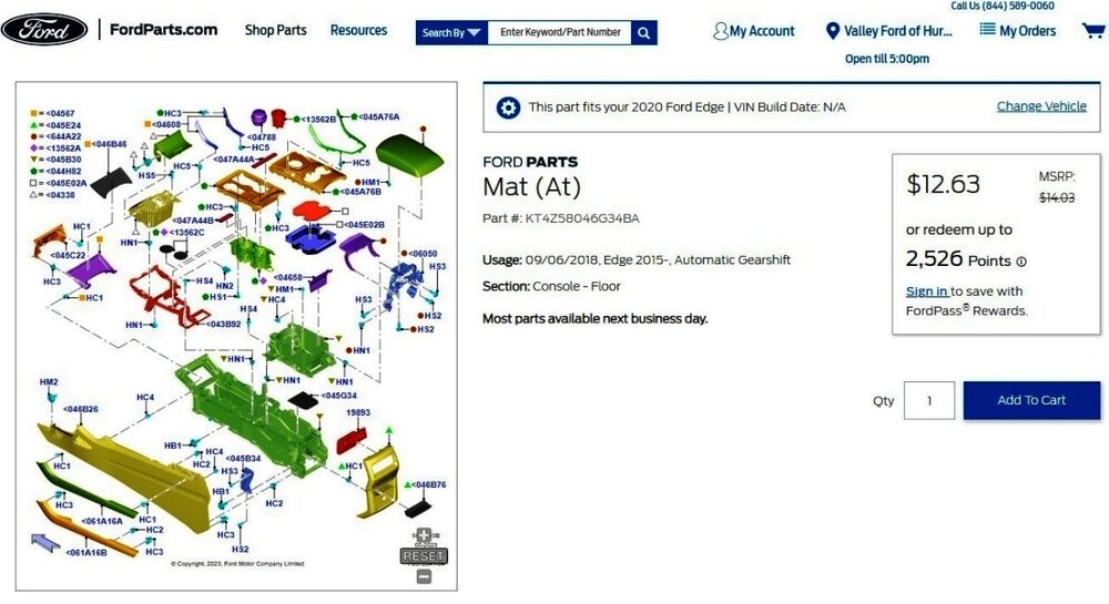
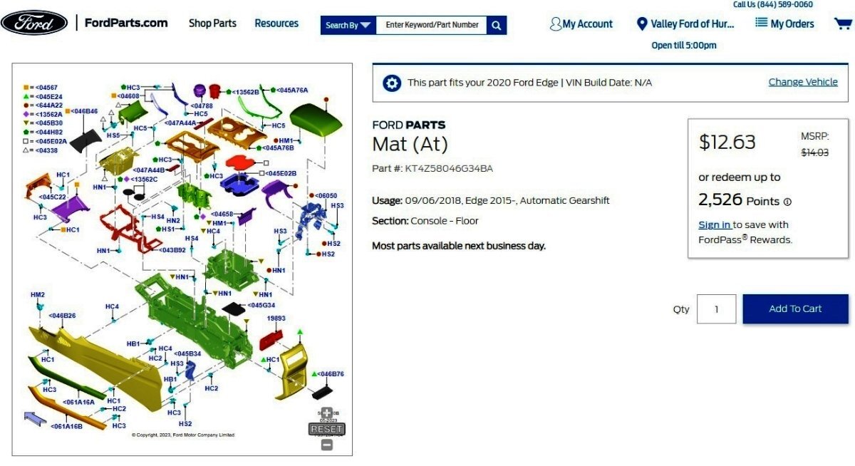
Insert for compartment located on console
Haz replied to Keith1341's topic in 2019-Current Edge & Nautilius
Welcome to the Forum @Keith1341! Link to this FordParts webpage (Page will populate after you Select Vehicle as 2020 Ford Edge) Good luck!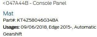
-
Tail Light Moisture Condensation 2019-2024
Haz replied to Wubster100's topic in 2019-Current Edge & Nautilius
@Wubster100: Your Edge might qualify for a warranty replacement. From General Service Bulletin 24-7068 - Various Vehicles - Exterior Lighting Concern Analysis... Examples Of Water Leaks (Figures 6-8) - Warrantable Figure 6 - example of water leak (large droplets) - warrantable Figure 7 - example of water leak (streaking) - warrantable Figure 8 - example of water leak (pooling at bottom) - warrantable Good luck! -
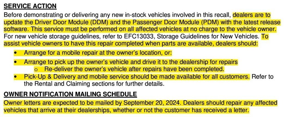
The Dealer Bulletin on Compliance Recall 24C24 has been released...
-
OCCASIONAL brief occurrences of exhaust fumes in interior
Haz replied to Phineas's topic in Recalls, TSBs & Warranty
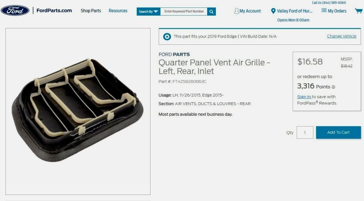
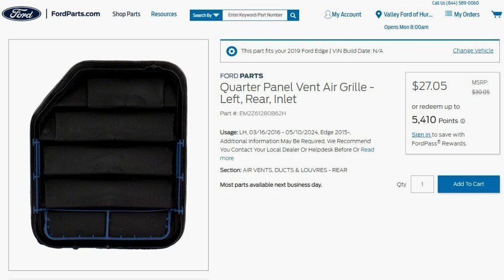
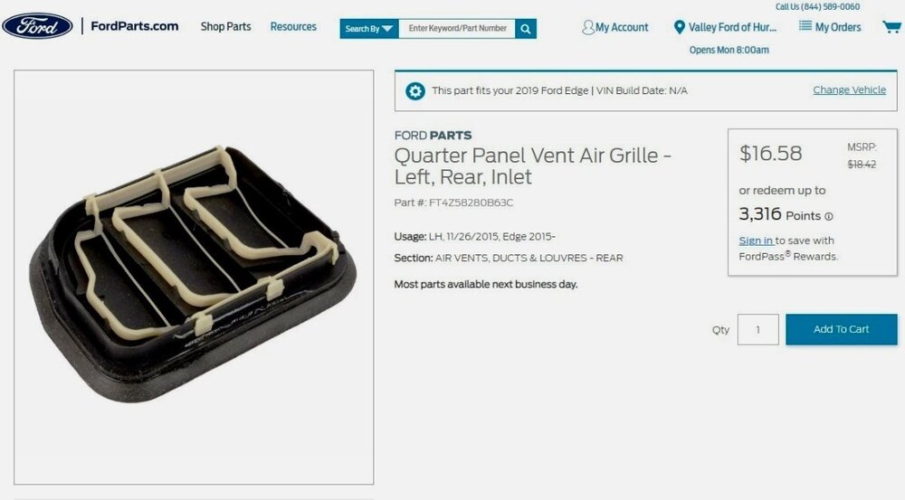
There is no comparable TSB for 2019 Edge, though your Edge has similar Quarter Panel Air Vent Grilles... Link to this FordParts webpage; Link to Right Hand version of this grille; Link to this FordParts webpage; Link to Right Hand version of this grille; The TSB mentions how Ford Warranty/Extended Service Plan (ESP) coverage is determined... When you take your Edge to the dealership, make sure you have the Service Advisor ride with you so that he/she first-hand experiences the exhaust odor and acceleration characteristics that produce the symptom, and perhaps take a copy of TSB 14-0201 with you. While the TSB is not directly applicable to your 2019 Edge, it does specify replacement of the Vent Air Grilles as a partial solution of the symptom. Additionally, the Service Advisor should be able to promptly determine if those replacement parts would be covered under your ESP contract. I expect the Service technician might remove the rear quarter interior trim, and then duplicate the vehicle acceleration with an assistant adjacent to the vent(s), to see if the odor can be localized to the vent(s). And as previously mentioned , changing fuel brands may affect the degree of rotten-egg odor -- for better or for worse. Good luck! Bumper Cover -- Rear - Removal and Installation - 2019 Edge Workshop Manual.pdf-HighlightedbyArrows-2019EdgeWorkshopManual.thumb.jpg.70d85cd4e02b68a7d1b8563b35bee430.jpg)
-HighlightedbyArrows-2019EdgeWorkshopManual.thumb.jpg.1f478c42251f4009f570287f86c087d4.jpg)
-
Ford edge 2014 rear camera not working
Haz replied to Cazz's topic in Audio, Backup, Navigation & SYNC
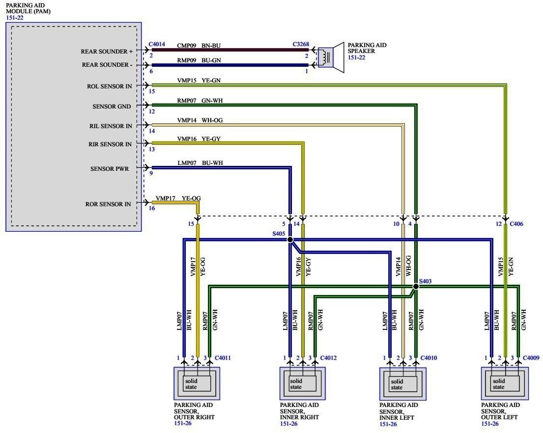
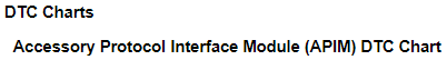
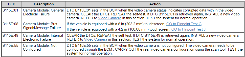
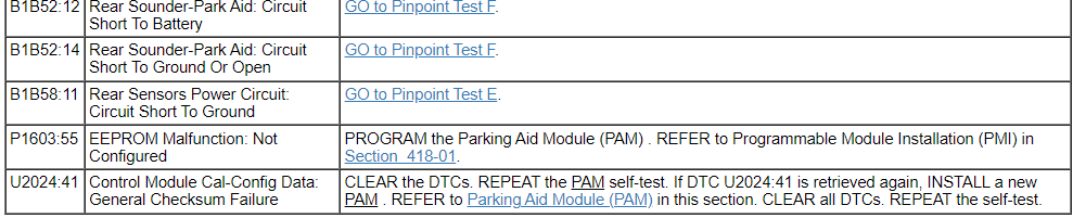
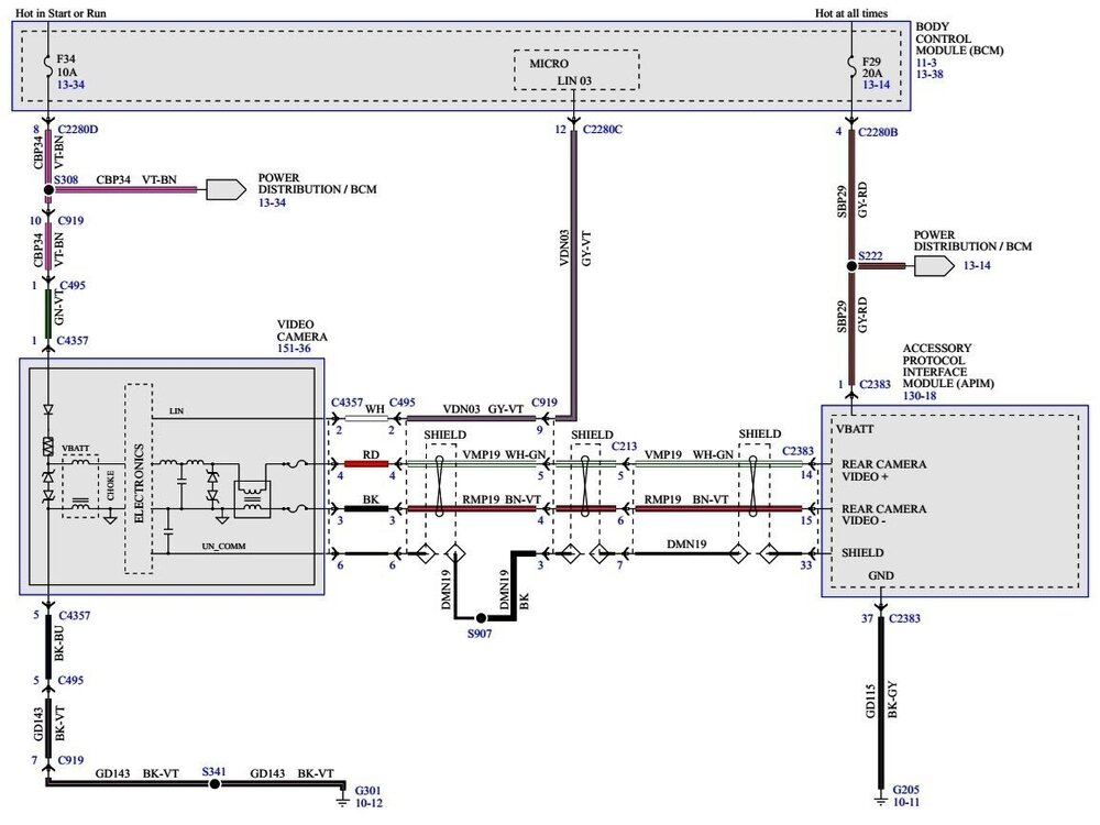
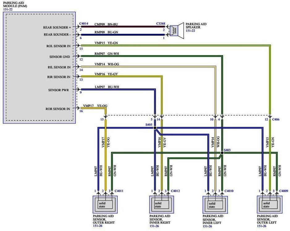
Welcome to the Forum @Cazz! From the 2014 Edge Workshop Manual... Placing your device cursor over underlines acronyms may yield popup full-words descriptions of the acronyms. Parking Aid — Video - Principles of Operation The rear video camera system is active with the ignition in run and the transaxle selector in the REVERSE (R) position. The video camera receives commands and sends status over a dedicated Local Interconnect Network (LIN) to the Body Control Module (BCM) . The video camera sends a video signal to the Accessory Protocol Interface Module (APIM) (vehicles equipped with a 8 in (203.2 mm) touchscreen) on a pair of shielded video circuits. The APIM sends the video signal to the Front Display Interface Module (FDIM) (mounted to the APIM ) which displays the video image of the area behind the vehicle. The messages sent from the BCM to the video camera are: transmission selector (PRNDL) status liftgate ajar status camera configuration data display manual zoom request parking aid audible warning status parking aid sensor distance to object data The messages sent from the video camera to the BCM are: camera status display zoom status camera part number data visual park aid alert status fixed guideline status Visual Inspection Chart Mechanical Electrical Liftgate and video camera Body Control Module (BCM) fuse 34 (10A) Wiring, terminals and connectors Video camera Front Display Interface Module (FDIM) (If equipped with 8 in (203.2 mm) touchscreen Body Control Module (BCM) Illustration with Fuse 34 (10 amp) location identified... If Fuse 43 is intact and not blown, then it would be useful to have your Edge scanned for Diagnostic Trouble Codes (DTCs), which may provide guidance toward correcting the rear camera video issue and the inactive Parking Aid sensors issue. If you or a friend or family member does not have this capability, then contact your local independent auto parts store or a national-brand auto parts store to see if they can scan your Edge and provide you a list of any DTCs found. Rear View Camera Wiring Diagram - SYNC 2 - MyFord Touch Parking Aid - Principles of Operation The parking aid sensors detect objects approximately 152 cm (60 in) from the rear of the vehicle, 50 cm (20 in) from the rear side of the vehicle, and 30 cm (12 in) above the ground. The Parking Aid Module (PAM) calculates the distance to an object within the 170 degree semicircular azimuth area around the rear of the vehicle. The parking aid system is enabled when the ignition switch is in the RUN position and the transmission in reverse. The parking aid system is disabled if a fault is detected in 1 of the 4 sensors, the parking aid speaker, or the PAM . This is indicated by a parking aid disabled warning message in the message center. The parking aid system is enabled and disabled through the message center, located in the Instrument Panel Cluster (IPC) . Visual Inspection Chart Electrical Body Control Module (BCM) fuse 34 (10A) Wiring, terminals or connectors Parking aid sensors Symptom Chart Condition Possible Causes Action The parking aid is inoperative Wiring, terminals or connectors Parking aid sensor alignment PAM Rear bumper GO to Pinpoint Test A. Parking Aid Module and Sensors and Speaker Wiring Diagram If you are inclined toward do-it-yourself diagnosis and repair, then I can provide the Pinpoint Test(s) that are indicated by DTCs revealed from having your Edge's electronic modules scanned. On the other hand, if you prefer to have a professional technician address the problem, then if you have your Edge scanned first, any resulting DTCs, combined with the information provided here, can provide you talking points with a professional technician. Good luck!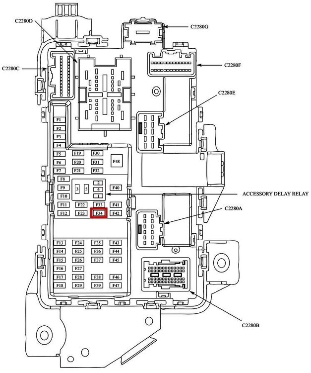


-
2022 Edge Touch screen removal
Haz replied to Majestick19's topic in Audio, Backup, Navigation & SYNC
Welcome to the Forum @Majestick19! Relevant sections from the 2022-2024 Edge Workshop Manual are attached below a PDF documents... Good luck! Center Display Screen - Removal and Installation - 2022-2024 Edge Workshop Manual.pdf Floor Console - Removal and Installation - 2022-2024 Edge Workshop Manual.pdf -
2017 Edge SEL Audio/Speaker Issues
Haz replied to BrandoM's topic in Audio, Backup, Navigation & SYNC
To assess the functionality of your Edge's speakers, try using one of the below-attached Bezel Diagnostics procedures to perform a Speaker Walkaround Test. From the 2017 Edge Workshop Manual, if your Edge SEL is equipped with the AM/FM/CD/SYNC audio system... Placing your device's cursor over underlined acronyms may yield popup full-words descriptions of the acronyms. The audio system consists of the following: Main Components 6 speakers 4.2-inch (107 mm) non-touchscreen FCDIM ACM APIM Audio input jack (if equipped) FCIM USB port/cable GPSM RH steering wheel audio controls Main Features Audio extended play Battery load shed Compass MyKey® Speed compensated volume SYNC® SYNC® AppLink™ ...then use this Bezel Diagnostics procedure... Bezel Diagnostics - Vehicles With AM-FM-CD-SYNC - 2017 Edge Workshop Manual.pdf If your Edge SEL is equipped with the Premium Audio 9-Speakers audio system with Touchscreen... The audio system consists of the following: Main Components 9 speakers 8-inch (203 mm) FDIM touchscreen ACM APIM FCIM USB hub RH audio steering wheel switches Main Features AM radio Audio extended play Battery load shed Compass FM radio HD Radio® (if equipped) MyKey® Navigation (if equipped) Satellite radio SIRIUS Travel Link (if equipped) Speed compensated volume SYNC® SYNC® AppLink™ ...then use this Bezel Diagnostics procedure... Bezel Diagnostics - Vehicles With Touchscreen Display - 2017 Edge Workshop Manual.pdf If the Speaker Walkaround Test does not produce results for any speaker, then have your Edge scanned for Diagnostic Trouble Codes (DTCs), and report back here with any DTCs that were found. Good luck!
- 1 reply
-
- 1
-

-
SSM 52841 2025 Explorer/Aviator Built On Or Before 14-Jun-2024, 2024 Nautilus - Map Is Blank Or Map Feature Is Inoperative When Vehicles Equipped with Google Automotive Services (Minor Feature Code HKCGA And IEPAT) Some 2025 Explorer/Aviator vehicles built on or before 14-Jun-2024 and 2024 Nautilus vehicles may exhibit a concern where the map is blank or the map feature is inoperative in the vehicle's center display screen on vehicles equipped with Google Navigation Automotive Services (minor feature code HKCGA and IEPAT). To confirm a vehicle is built with a certain minor feature code, review the build information by double-clicking the vehicle identification number (VIN) in the upper left corner in the Professional Technician System (PTS). This may be due to customer not activating their vehicle’s connectivity via FordPass/LincolnWay app. Advise the customer to activate their vehicle’s connectivity by adding their VIN to FordPass/LincolnWay app > Activate Vehicle on the FordPass/LincolnWay app > Accept pop-up in the vehicle's center display screen.
-
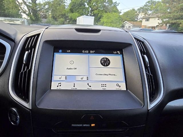
SSM 52840 2024 Nautilus, 2025 Explorer/Aviator - Wireless Charger Icon Inaccurate Some 2024 Nautilus and 2025 Explorer/Aviator vehicles may exhibit a concern with the wireless charger icon on the vehicle's center display screen where the icon does not display while the phone is charging or the icon displaying with no phone on the charger. This may be due to accessory protocol interface module (APIM) software. Replacement or reprogramming of the APIM will not resolve this condition. Inform customers that engineering is currently working on a solution for this condition and will be released via software updates delivered over-the-air (OTA) expected Q4, 2024. If the wireless charger is inoperative, follow Workshop Manual, Section 414-06 to further diagnose the concern.
-
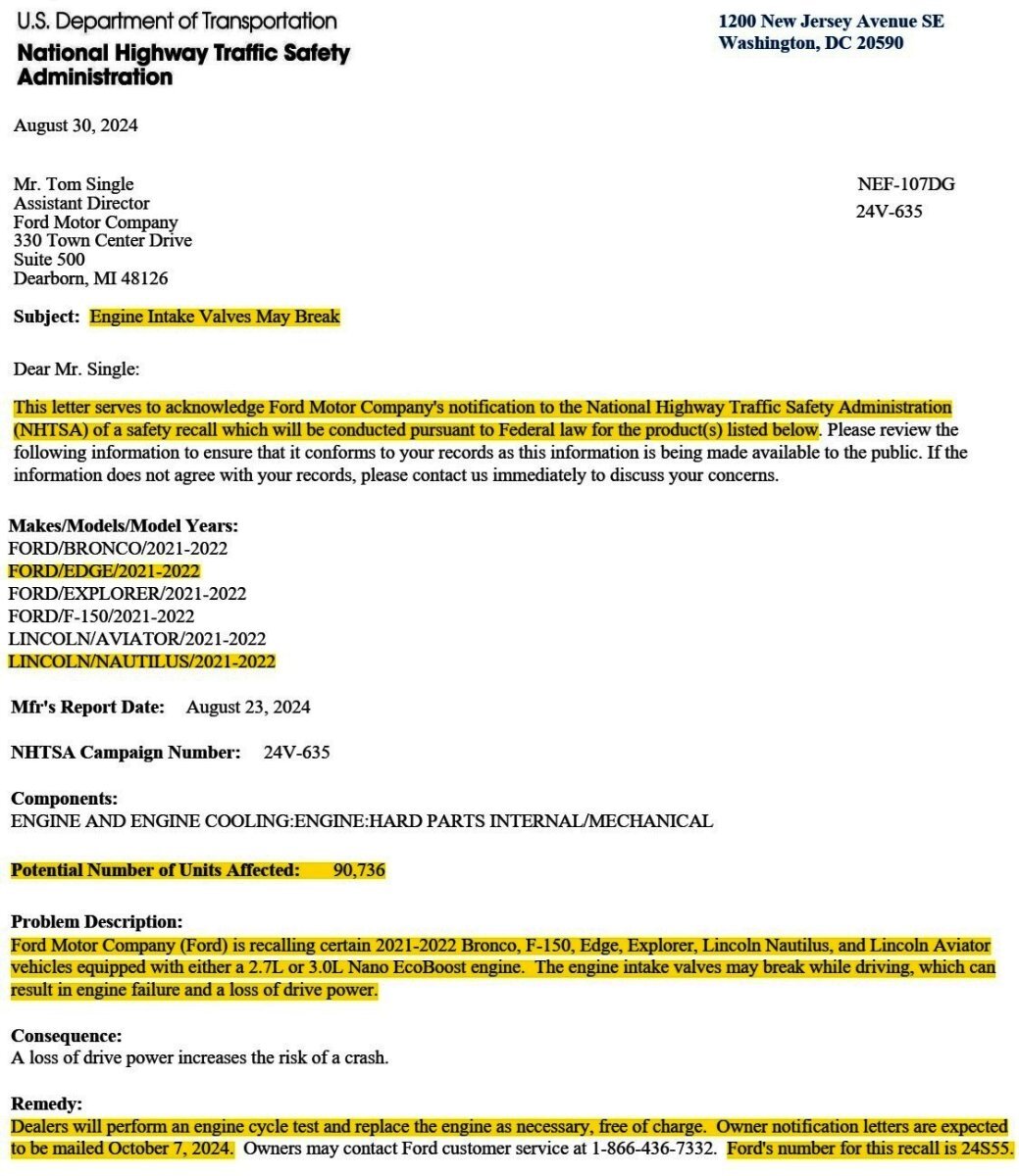
Pending Ford's release of the Safety Recall 24S55 Dealer Bulletin, the following NHTSA Letter will temporarily serve as its informational placeholder...

-
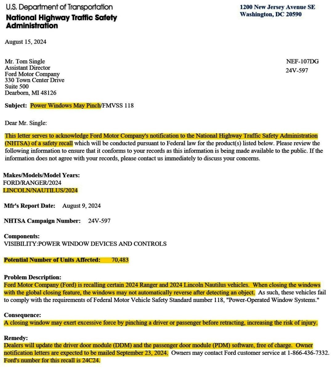
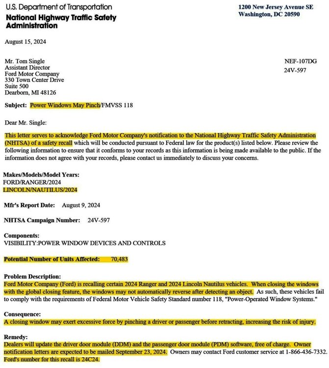
Pending Ford's release of the Safety Recall 24C24 Dealer Bulletin, the following NHTSA Letter will temporarily serve as its informational placeholder... Gratitude to @markfm for bringing this to my attention.
-
Small range of the remote
Haz replied to MoOsa's topic in Alarms, Keyless Entry, Locks & Remote Start
I understand from your Forum message that Remote Starting System components were added to your Edge and were activated by a dealer in your area. If Ford OEM parts -- whether new or salvaged from another Ford vehicle -- were installed in your Edge, then Pinpoint Test E should be useful toward determining why the horrible remote-starting performance of only 10 feet is occurring. Scanning your Edge for this Diagnostic Trouble Code (DTC) would be a good first-step... DTC B1D55:01 (Antenna #2: General Electrical Failure) — this DTC is set if the vehicle is equipped with remote start but the system feedback circuit does not detect an external antenna. Attached below as a PDF document is Pinpoint Test E, which you can provide the dealer - whether Ford or a different vehicle brand -- to guide them toward correcting the distance-performance issue the Edge is exhibiting after their installation and activation of Remote Starting System components. Good luck! Remote Starting System - Diagnostic Pinpoint Test E - 2014 Edge Workshop Manual.pdf -
Edge ST 2022, Ambient light in the cupholder
Haz replied to hsprime85's topic in Interior, A.C., Heat, Interior Trim
BODY CONTROL MODULE (BCM) - Connector C2280F Pin-Circuit Details - 2022 Edge Wiring Resource.pdf Good luck! -
FordPass no longer can connect to vehicle?
Haz replied to eric1's topic in Audio, Backup, Navigation & SYNC
@eric1: Ford's advice to dealers on updating APIM software to address FordPass connectivity issues... Special Service Message 52722 - 2019–2024 Ford And Lincoln Vehicles - Equipped With SYNC3 - Various FordPass/LincolnWay Connectivity Concerns With DTC B156D:89 Stored The Telematics Control Unit Module (TCU) Good luck! -
Edge ST 2022, Ambient light in the cupholder
Haz replied to hsprime85's topic in Interior, A.C., Heat, Interior Trim
@Wubster100: Per your request, attached below as PDF document(s)... Good luck! BODY CONTROL MODULE (BCM) - Connector C2280D Location - 2022 Edge Wiring Resource.pdf BODY CONTROL MODULE (BCM) - Illustration showing wiring harness connector locations - 2022 Edge Wiring Resource.pdf BODY CONTROL MODULE (BCM) - Connector C2280D Pin-Circuit Details - 2022 Edge Wiring Resource.pdf -
Small range of the remote
Haz replied to MoOsa's topic in Alarms, Keyless Entry, Locks & Remote Start
Welcome to the Forum @MoOsa! From your comments, it is not clear to me if the Remote Starting System on your Edge was factory-installed, or, if it is a dealer-installed or owner-installed Ford Accessories Remote Start System. The following diagnostic Pinpoint Test E is from the 2014 Edge Workshop Manual... Placing your device cursor over underlined acronyms may yield pop-up full-words descriptions of the acronyms. Pinpoint Test E: Poor Remote Start Range Normal Operation Vehicles with remote start have an additional external antenna connected to the Tire Pressure Monitor Module (TPM) to extend the RKE range. The Tire Pressure Monitor Module (TPM) receives a signal from the Integrated Keyhead Transmitter (IKT) or Intelligent Access (IA) key to enable activation of the remote start function from a distance of up to 100 meters (328 feet). DTC B1D55:01 (Antenna #2: General Electrical Failure) — this DTC is set if the vehicle is equipped with remote start but the system feedback circuit does not detect an external antenna. This pinpoint test is intended to diagnose the following: Integrated Keyhead Transmitter (IKT) External antenna External antenna lead TPM Wiring, terminals or connectors PINPOINT TEST E : POOR REMOTE START RANGE NOTE: Aftermarket or dealer-installed systems can adversely affect the RKE system operation. These systems must be disconnected before diagnosing any RKE concerns. E1 CHECK FOR THE CORRECT RKE TRANSMITTERS NOTE: Make sure the RKE transmitters are those provided with the OEM system and not from an aftermarket system, or a dealer-installed system that may have been installed on the vehicle. Check that the correct IKTs are used with the vehicle. Compare the IKTs with the one shown in Section 501-14 in the Description and Operation. Are the correct RKE transmitters present? Yes GO to E2. No The system cannot be tested without the correct RKE transmitters. INFORM the customer that the correct RKE transmitters must be present to proceed with diagnosis of the system. E2 CHECK ALL RKE TRANSMITTERS FOR POOR RANGE PERFORMANCE NOTE: The 100 m (328 ft) measurement of range is not the standard but is a guideline that clearly indicates a vehicle is experiencing normal range performance. Check all RKE transmitters for poor range performance (less than 100 m [328 ft]). Do all RKE transmitters experience poor range? Yes GO to E4. No GO to E3. E3 CHECK THE IKT BATTERY Using a thin coin, open the weak IKT . Do not clean off any grease from the battery terminals on the back surface of the circuit board. Verify the correct battery is used (CR2032). Remove the IKT battery and measure the voltage. Is the voltage greater than 2.5 volts? Yes REPLACE the inoperative IKT and PROGRAM the new IKT individually or PROGRAM all the IKTs . REFER to Section 419-01B for the programming procedures. If all the IKTs are to be programmed, INFORM the customer that any IKTs not present need to be programmed. TEST the system for normal operation. No INSTALL a new battery (make sure the battery is seated correctly). DO NOT reprogram the IKT (weak or dead batteries do not erase TICs from memory). TEST the system for normal operation. E4 CHECK THE LOCATION OF THE VEHICLE AND THE APPROACH ANGLES AROUND THE VEHICLE Make sure the poor performance is consistent in nature and is not from one approaching angle. The RKE transmitter range performance may be degraded in certain locations. For example, if the vehicle is within 0.5 mile (0.8 km) of high-power devices or radio/TV towers, the operating distance of the RKE transmitters may be reduced. Is the poor range performance consistent around the vehicle? Yes GO to E5. No The system is operating correctly at this time. The range may have been affected by environmental interference. E5 CHECK THE EXTERNAL ANTENNA CONNECTION Access the TPM . Section 204-04. Check the connections at the external antenna and TPM . Are the connections loose or disconnected? Yes REPAIR as necessary. CLEAR the DTCs. REPEAT the self-test. TEST the system for normal operation. No GO to E6. E6 CHECK THE EXTERNAL ANTENNA INSTALL a new external antenna. ATTEMPT to start the vehicle using the IKT from a distance of 100 meters (328 feet) from the vehicle. Does the vehicle start from this distance? Yes System is operating correctly at this time. CLEAR the DTCs. REPEAT the self-test. TEST the system for normal operation. No GO to E7. E7 CHECK THE EXTERNAL ANTENNA CABLE INSTALL a new external antenna cable. CLEAR the DTCs. REPEAT the self-test. TEST the system for normal operation. ATTEMPT to start the vehicle using the IKT from a distance of 100 meters (328 feet) from the vehicle Does the vehicle start from this distance? Yes System is operating correctly at this time. CLEAR the DTCs. REPEAT the self-test. TEST the system for normal operation. No INSTALL a new TPM . REFER to Section 204-04. CLEAR the DTCs. REPEAT the self-test. TEST the system for normal operation. Attached below as PDF documents are relevant sections from the 2014 Edge Workshop Manual, as well as the installation-activation-functional testing manual for the Ford Accessories add-on Remote Start System... Good luck! Tire Pressure Monitor (TPM) Module + Remote Start Antenna - Removal and Installation - 2014 Edge Workshop Manual.pdf Quarter Trim Panel - Removal and Installation - 2014 Edge Workshop Manual.pdf Power Liftgate Motor - Removal and Installation - 2014 Edge Workshop Manual.pdf Scuff Plate Trim Panel — Rear - Removal and Installation - 2014 Edge Workshop Manual.pdf Interior Trim — Exploded View - 2014 Edge Workshop Manual.pdf Ford Accessories - Remote Start System - Installation + Activation + Functional Testing Procedures - 2014 Edge.pdf -
OCCASIONAL brief occurrences of exhaust fumes in interior
Haz replied to Phineas's topic in Recalls, TSBs & Warranty
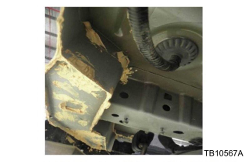
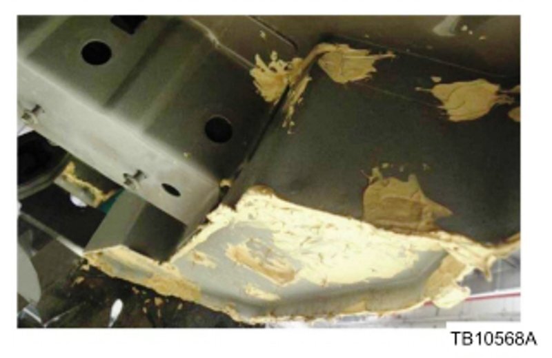
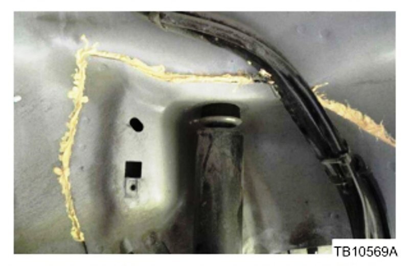
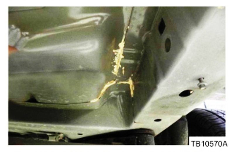
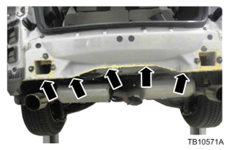
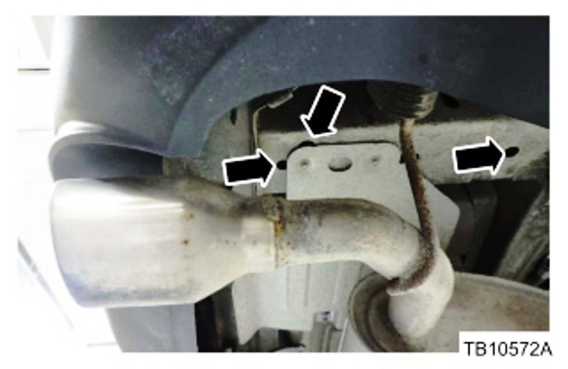
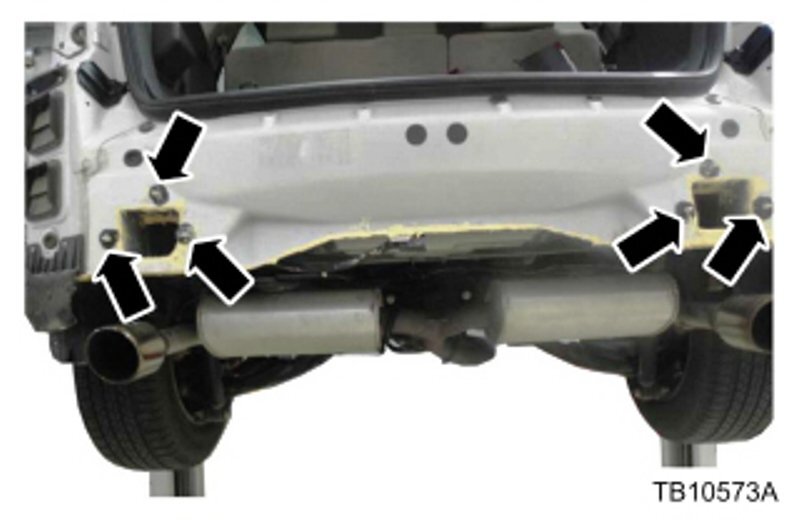
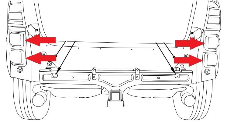
Welcome to the Forum @Phineas! From your earlier research, you may be recalling the following Technical Service Bulletin (TSB), which is Ford's recommended Service action when the described symptoms are present, in this case, when the Climate Control system is set to Recirculation Mode... TSB 14-0201 EXHAUST SULFUR ODOR AFTER HARD ACCELERATION - CLIMATE CONTROL IN RECIRCULATION MODE ONLY Publication Date: October 28, 2014 FORD: 2011-2014 Edge LINCOLN: 2011-2015 MKX ISSUE: Some 2011-2014 Edge and 2011-2015 MKX vehicles may exhibit an exhaust odor in the vehicle while the climate control system is in recirculation mode only. This may be more noticeable after hard acceleration, driving in hilly conditions and/or towing a trailer. Customers may indicate the odor smells like sulfur. ACTION: Follow the Service Procedure steps to correct the condition. SERVICE PROCEDURE Remove the rear bumper. Refer to Workshop Manual (WSM), Section 501-19. Replace the four (4) air extractors. Lower and support the rear section of the exhaust system. Clean the areas on the underside of vehicle where seam sealer and expandable foam will be applied. (Figures 1-6) Cover the exhaust system. Apply a generous amount of Motorcraft® Seam Sealer to the rear horizontal sheet metal lap joints on the left and right sides of the vehicle and the rear sheet metal overlap flange across the rear of the vehicle. (Figures 1-6) Figure 1 - 14-0201 Figure 2 - 14-0201 Figure 3 - 14-0201 Figure 4 - 14-0201 Figure 5 - 14-0201 Figure 6 - 14-0201 Figure 7 - 14-0201 Fill crush cans with Lord Fusor 130 or 3M 08458 expandable foam. Follow the instructions on the can for application. (Figure 7) Install foam from the Rotunda Squeak and Rattle Repair Kit (164-R4901) around the bumper beam attachment studs. (Figure 😎 Figure 8 - 14-0201 Some vehicle configurations may have unused bumper attachment studs on each side of the vehicle. Apply Motorcraft Seam Sealer around unused studs. (Figure 😎 Reinstall the rear exhaust system. Reinstall the rear bumper cover. Refer to WSM, Section 501-19. Reprogram the heating ventilation air conditioning (HVAC) module to the latest calibration using IDS release 92.04 or higher. Make sure you are connected to the internet when entering module programming to obtain the latest updates. Calibration files may also be obtained at www.motorcraftservice.com. Obtain Locally Part Number Part Description 130 Lord Corporation Fusor® Rigid Foam (Super Fast) 08458 3M Rigid Pillar Foam PART NUMBER PART NAME AL2Z-61280B62-A Grille - Air Inlet TA-2-B Motorcraft® Seam Sealer OPERATION DESCRIPTION TIME 140201A 2011-2014 Edge, 2011-2015 MKX: Seal The Body Includes Time To Replace Air Extractors And Reprogram The HVAC Module (Do Not Use With Any Other Labor Operations) 1.8 Hrs. WARRANTY STATUS Eligible Under Provisions Of New Vehicle Limited Warranty Coverage. Warranty/ESP coverage limits/policies/prior approvals are not altered by a TSB. Warranty/ESP coverage limits are determined by the identified causal part and verified using the OASIS part coverage tool. DEALER CODING BASIC PART NO. CONDITION CODE 61280B62 34 NOTE: The information in Technical Service Bulletins is intended for use by trained, professional technicians with the knowledge, tools, and equipment to do the job properly and safely. It informs these technicians of conditions that may occur on some vehicles, or provides information that could assist in proper vehicle service. The procedures should not be performed by "do-it-yourselfers". Do not assume that a condition described affects your car or truck. Contact a Ford or Lincoln dealership to determine whether the Bulletin applies to your vehicle. Warranty Policy and Extended Service Plan documentation determine Warranty and/or Extended Service Plan coverage unless stated otherwise in the TSB article. The information in this Technical Service Bulletin (TSB) was current at the time of printing. Ford Motor Company reserves the right to supercede this information with updates. The most recent information is available through Ford Motor Company's on-line technical resources. Copyright © 2014 Ford Motor Company Link to this FordParts webpage The followed red-arrowed illustrations depict the installed Air Vent Grilles and the Rear Quarter body openings into which they snap-fit... If you are not inclined to personally undertake this repair, your dealer should be able to provide a firm cost-estimate, based upon the TSB's Parts list and 1.8 hours of Labor charge. Attached below as PDF documents are TSB 14-0201 and related 2014 Edge-MKX Workshop Manual Sections... I do wonder if, through the course of your workday, your repeated opening of the driver's door may be creating a brief negative cabin pressure that could be pulling-in small amounts of sulfur/rotten-egg exhaust odor. Additionally, the sulfur content of fuel varies, so trying a different fuel brand may alter the amount of rotten egg odor. Good luck! TSB 14-0201 - Exhaust Sulfur Odor After Hard Acceleration - Climate Control in Recirculation Mode Only.pdf Bumper Cover, Rear - Removal and Installation - 2014 Edge-MKX Workshop Manual.pdf Bumper, Rear - Removal and Installation - 2014 Edge-MKX Workshop Manual.pdf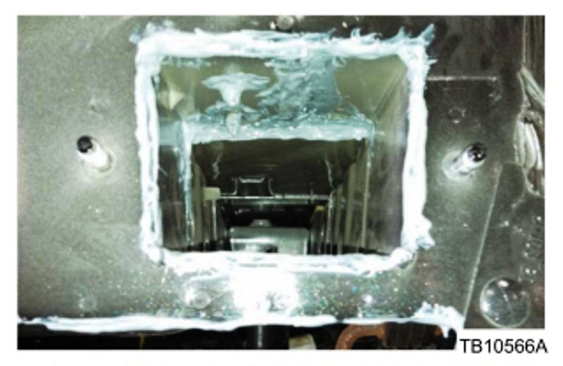
-
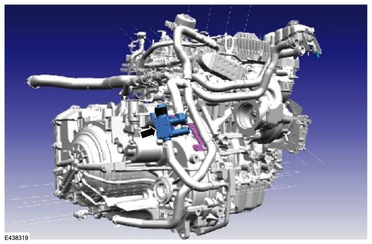
TECHNICAL SERVICE BULLETIN 2.0L EcoBoost - Illuminated MIL With DTCs P0401 Or P2457 And/Or Various Engine Cooling System Symptoms From Transmission Fluid Heater Coolant Control Valve Blockage - Built On 28-Aug-2023 And Through 02-Apr-2024 24-2263 26 August 2024 Model: Ford 2024 Edge Vehicle built on 28-Aug-2023 and through 02-Apr-2024 Engine: 2.0L EcoBoost Lincoln 2023 Nautilus Vehicle built on 28-Aug-2023 and through 02-Apr-2024 Engine: 2.0L EcoBoost Markets: North American markets only Issue: Some 2024 Edge and 2023 Nautilus vehicles built on 28-Aug-2023 and through 02-Apr-2024 equipped with a 2.0L EcoBoost engine may experience an illuminated MIL with DTC P0401 or P2457. Various engine cooling system symptoms which may include an internal/external leak, white smoke from the tailpipe, and/or over-temperature warnings may also be present. This may be due to a transmission fluid heater coolant control valve restricting flow and possibly causing the EGR cooler to crack. To correct the condition, follow the Service Procedure to replace the affected parts. Action: Follow the Service Procedure to correct the condition on vehicles that meet all of the following criteria: • One of the following vehicles: - 2024 Edge - 2023 Nautilus • Vehicle built on 28-Aug-2023 and through 02-Apr-2024 • 2.0L EcoBoost engine • Illuminated MIL with DTCs P0401 or P2457 • Various engine cooling system symptoms which may include an internal/external leak, white smoke from the tailpipe, and/or over-temperature warnings Parts Service Part Number Claim Quantity Package Order Quantity Number in Package Description K2GZ-9F464-B 1 1 1 EGR Cooler (Includes Gaskets) K2GZ-18495-B 1 1 1 Transmission Fluid Heater Coolant Control Valve Parts - Parts To Inspect And Replace Only If Necessary Service Part Number Claim Quantity Package Order Quantity Number in Package Description K2GZ-6758-H Only If Necessary (1 Possible) Only If Necessary (1 Possible) 1 Crankcase Ventilation Tube XL-2 Only If Necessary Only If Necessary Motorcraft® High Temperature Nickel Anti-Seize Lubricant ZC-37-A Only If Necessary Only If Necessary Motorcraft® Wheel and Tire Cleaner XG-3-A Only If Necessary Only If Necessary Motorcraft® Silicone Brake Caliper Grease and Dielectric Compound VC-13-G Only If Necessary Only If Necessary Motorcraft® Yellow Concentrated Antifreeze/Coolant (All Markets Except Canada) CVC-13-G Only If Necessary Only If Necessary Motorcraft® Yellow Concentrated Antifreeze/Coolant (Canada Only) Warranty Status: Eligible under provisions of New Vehicle Limited Warranty (NVLW)/Emissions Warranty/Service Part Warranty (SPW)/Service Part New Vehicle (SPNV)/Extended Service Plan (ESP) coverage. Limits/policies/prior approvals are not altered by a TSB. NVLW/Emissions Warranty/SPW/SPNV/ESP coverage limits are determined by the identified causal part and verified using the OASIS part coverage tool. Labor Times Description Operation No. Time 2023 Nautilus, 2024 Edge 2.0L EcoBoost: Replace The Transmission Fluid Heater Coolant Control Valve And The EGR Cooler (Do Not Use With Any Other Labor Operations) 242263A 3.3 Hrs. Repair/Claim Coding Causal Part: 18495 Condition Code: 55 Service Procedure 1. Replace the transmission fluid heater coolant control valve. Refer to WSM, Section 303-03A. (Figure 1) Figure 1 2. Replace the EGR cooler. Refer to WSM, Section 303-08A. © 2024 Ford Motor Company All rights reserved. NOTE: The information in Technical Service Bulletins is intended for use by trained, professional technicians with the knowledge, tools, and equipment to do the job properly and safely. It informs these technicians of conditions that may occur on some vehicles, or provides information that could assist in proper vehicle service. The procedures should not be performed by "do-it-yourselfers". Do not assume that a condition described affects your car or truck. Contact a Ford or Lincoln dealership to determine whether the Bulletin applies to your vehicle. Warranty Policy and Extended Service Plan documentation determine Warranty and/or Extended Service Plan coverage unless stated otherwise in the TSB article. The information in this Technical Service Bulletin (TSB) was current at the time of printing. Ford Motor Company reserves the right to supersede this information with updates. The most recent information is available through Ford Motor Company's on-line technical resources. Attached below as PDF documents are this TSB and the two above-referenced Workshop Manual sections... Exhaust Gas Recirculation (EGR) Cooler - Removal and Installation - 2022-2023 Nautilus Workshop Manual.pdf TSB 24-2263 - 2023 Nautilus, 2024 Edge - 2.0L EcoBoost - Illuminated MIL With DTCs And-Or Various Engine Cooling System Symptoms - 08-28-2023 to 04-02-2024.pdf Transmission Fluid Heater Coolant Control Valve - Removal and Installation - 2022-2023 Nautilus Workshop Manual.pdf
-
Welcome to the Forum @interceptor859! While I have no experience with this Buffalo, Minnesota online seller with an A+ BBB rating, they offer the wheels you are seeking for $360.95 each with free shipping... Take a look around their website and perhaps give them a call to assess your comfort level with their refinishing & business practices. If you prefer to first-hand see what you're buying, it wouldn't be a horrible drive up from Kentucky, though the free shipping with 100% satisfaction guarantee is an attractive offer. Good luck!
-
From the Edge-Nautilus 2.0L EcoBoost Workshop Manual, regarding the P0420 Diagnostic Trouble Code (DTC)... Placing your device cursor over underlined acronyms may yield pop-up full-words descriptions of the acronyms. DTC Fault Trigger Conditions DTC Description Fault Trigger Condition PCM P0420:00 Catalyst System Efficiency Below Threshold Bank 1: No Sub Type Information Sets when PCM detects the bank 1 catalyst system efficiency is below the acceptable threshold. Under normal closed loop fuel conditions, high efficiency catalysts have oxygen storage capability. As catalyst efficiency deteriorates, its ability to store oxygen declines. Refer to the Catalyst Efficiency Monitor description for additional information. Diagnose any base engine concerns. Refer to the appropriate 303-00 section, Engine System. Possible Causes HO2S 2WD 4WD circuitry concern Exhaust system concern Contaminated oil Base engine concern Fuel injector Turbocharger HO2S


-HighlightedbyArrows-2019EdgeWorkshopManual.jpg.67ca51e653bf555d2301cc56157de20b.jpg)
-HighlightedbyArrows-2019EdgeWorkshopManual.jpg.450b22022210b1e45934123103dfe676.jpg)