Haz
-
Posts
1,568 -
Joined
-
Last visited
-
Days Won
439
Content Type
Profiles
Forums
Gallery
Everything posted by Haz
-
Heating/cooling for both front seats is regulated by Driver Side Front Seat Module (DSM) that you have pictured. Power to the DSM is protected by fuses F74 and F77, located beneath the underside cover of the Battery Junction Box. From the 2020 Edge Workshop Manual and Wiring Resource, attached below as PDF documents... Good luck! Climate Controlled Seats - Power Distribution - Wiring Diagram - 2020 Edge.pdf Climate Controlled Seats, Left Hand - Wiring Diagram - 2020 Edge.pdf Climate Controlled Seats, Right Hand - Wiring Diagram - 2020 Edge.pdf Driver Front Seat Module (DSM) Connectors Loctation Illustration - 2020 Edge.pdf Front Seats - System Operation and Component Description - 2020 Edge Workshop Manual.pdf Driver Front Seat Module (DSM) - Removal and Installation - 2020 Edge Workshop Manual.pdf Battery Junction Box (BJB) - Top View - 2020 Edge.pdf Battery Junction Box (BJB) - Bottom View - 2020 Edge.pdf Battery Junction Box (BJB) - Fuse-Circuits Listing #1 - 2020 Edge.pdf Battery Junction Box (BJB) - Fuse-Circuits Listing #2 - 2020 Edge.pdf
-
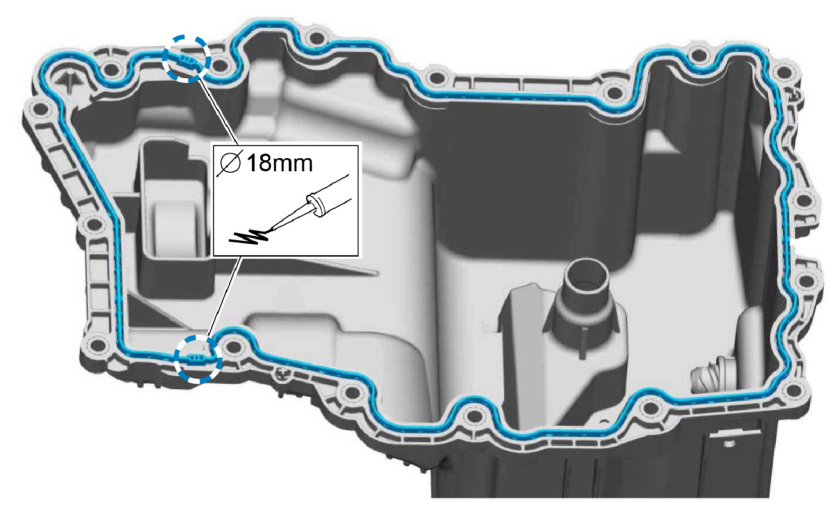
TSB 24-2345 - 2.7L EcoBoost & 3.0L EcoBoost - Oil Pan Leaking.pdf TECHNICAL SERVICE BULLETIN 2.7L/3.0L EcoBoost - Oil Pan Leaking 24-2345 25 November 2024 This bulletin supersedes 23-2338. Reason for update: revised Service Procedure, update Part List Model: Ford 2015-2017 Edge Engine: 2.7L EcoBoost 2017 Fusion Engine: 2.7L EcoBoost Lincoln 2017 Continental Engine: 2.7L EcoBoost Engine: 3.0L EcoBoost 2016-2017 MKX Engine: 2.7L EcoBoost 2017 MKZ Engine: 3.0L EcoBoost Markets: North American markets only Issue: Some 2015-2017 Edge, 2016-2017 MKX, 2017 Fusion/MKZ/Continental vehicles equipped with a 2.7L EcoBoost or 3.0L EcoBoost engine may exhibit an oil leak from the engine oil pan RTV seal. This may be due to a lack of RTV adhesion. To correct the condition, follow the Service Procedure to replace the factory oil pan with a press in place gasket style oil pan. Action: Follow the Service Procedure to correct the condition on vehicles that meet all of the following criteria: • One of the following vehicle lines: - 2015-2017 Edge - 2016-2017 MKX - 2017 Continental/Fusion/MKZ • 2.7L/3.0L EcoBoost engine • Oil leak from the oil pan RTV seal Parts Service Part Number Claim Quantity Package Order Quantity Number in Package Description FT4Z-6675-D 1 1 1 Oil Pan FL3Z-6710-B 1 1 1 Oil Pan Gasket KU2Z-6731-A 1 1 1 Oil Filter Element And O-Ring Seals FT4Z-6A832-C 1 1 1 Oil Filter and Cap Assembly Kit 9W7Z-19B596-A 1 1 1 Seal Kit - A/C Compressor Gasket And O-Ring, 1/2 In. (Edge/MKX Only) DL3Z-19B596-B 1 1 1 Seal Kit - A/C Compressor Gasket And O-Ring, 5/8 In. (Continental 2.7L Only) DS7Z-19B596-A 1 1 1 Seal Kit - A/C Compressor Gaskets 8 mm, 1/2 In., 5/8 In. (All Models) HL3Z-19B596-A 1 1 1 Seal Kit - A/C O-Rings - 3/4 In., 1/2 In., 5/8 In. and 3/8 In. (Fusion/MKZ/Continental 3.0L) FT4Z-6626-A 1 1 1 Oil Pump Seal W714265-S442 1 1 4 Left Catalytic Converter Nuts BL3Z-9450-A 1 1 1 Catalytic Converter Gasket Parts - Parts To Inspect And Replace Only If Necessary Service Part Number Claim Quantity Package Order Quantity Number in Package Description ZC-30-A Only If Necessary Only If Necessary Motorcraft® Gasket Remover TA-357 Only If Necessary Only If Necessary Motorcraft® High Performance Engine RTV Silicone XO- 5W30-Q1SP Only If Necessary Only If Necessary Motorcraft® SAE 5W-30 Synthetic Blend Motor Oil (All Markets Except Canada) CXO-5W30-LSP6 Only If Necessary Only If Necessary Motorcraft® SAE 5W-30 Super Premium Motor Oil (Canada Only) VC-13-G Only If Necessary Only If Necessary Motorcraft® Yellow Concentrated Antifreeze/Coolant (All Markets Except Canada) CVC-13-G Only If Necessary Only If Necessary Motorcraft® Yellow Concentrated Antifreeze/Coolant (Canada Only) PM-4-A Only If Necessary Only If Necessary Motorcraft® Brake Parts Cleaner - VOC Compliant (All Markets Except Canada) PM-4-B Only If Necessary Only If Necessary Motorcraft® Metal Brake Parts Cleaner (Not Compliant With Low Volatile Organic Compound [VOC] Requirements) (All Markets Except Canada) CPM-4-A Only If Necessary Only If Necessary Motorcraft® Brake Parts Cleaner - VOC Compliant (Canada Only) Claim Quantity refers to the total number of individual pieces required to repair the vehicle. Package Order Quantity refers to the amount of the service part number package(s) required to repair the vehicle. Number In Package refers to the number of individual pieces included in a service part number package. Only If Necessary indicates the part is not mandatory. Refer to the Service Procedure to determine the inspection/inclusion criteria. Labor Times Description Operation No. Time 2017 Continental 2.7L/3.0L EcoBoost: Inspect And Replace The Engine Oil Pan (Do Not Use With Any Other Labor Operations) 242345A 3.1 Hrs. 2015-2017 Edge, 2016-2017 MKX 2.7L EcoBoost: Inspect And Replace The Engine Oil Pan (Do Not Use With Any Other Labor Operations) 242345B 3.2 Hrs. 2017 Fusion 2.7L EcoBoost: Inspect And Replace The Engine Oil Pan (Do Not Use With Any Labor Operations Outside Of This Article) 242345C 3.2 Hrs. 2017 MKZ 3.0L EcoBoost: Inspect And Replace The Engine Oil Pan (Do Not Use With Any Labor Operations Outside Of This Article) 242345D 3.2 Hrs. Repair/Claim Coding Causal Part: 6675 Condition Code: D8 Service Procedure 1. Remove and discard the oil pan and oil pump seal. Refer to WSM, Section 303-01, Removal and Installation > Oil Pan. 2. Clean and prepare the engine sealing surface. Refer to WSM, Section 303-00 General Procedures. 3. Install the new oil pump seal. Refer to WSM, Section 303-01, Removal and Installation > Oil Pan. 4. Verify the correct orientation of the new press in place gasket and install the new oil pan. Refer to the WSM, Section 303-01, Removal and Installation > Oil Pan. (1). Apply an 18 mm bead of Motorcraft® High Performance Engine RTV Silicone at the T-joints, where the ladder frame meets the front cover (Figure 1) NOTE: The new oil pan does not require the use of Motorcraft® High Performance Engine RTV Silicone in any other location. Figure 1 © 2024 Ford Motor Company All rights reserved. NOTE: The information in Technical Service Bulletins is intended for use by trained, professional technicians with the knowledge, tools, and equipment to do the job properly and safely. It informs these technicians of conditions that may occur on some vehicles, or provides information that could assist in proper vehicle service. The procedures should not be performed by "do-it-yourselfers". Do not assume that a condition described affects your car or truck. Contact a Ford or Lincoln dealership to determine whether the Bulletin applies to your vehicle. Warranty Policy and Extended Service Plan documentation determine Warranty and/or Extended Service Plan coverage unless stated otherwise in the TSB article. The information in this Technical Service Bulletin (TSB) was current at the time of printing. Ford Motor Company reserves the right to supersede this information with updates. The most recent information is available through Ford Motor Company's on-line technical resources.
-
Welcome to the Forum @MDrumm03! So, if it is 2010 wiring diagrams you are seeking, they are attached to my earlier post above -- all those documents are for 2010 Model Year Edge. The 2011 Edge wiring diagram and 2010 & 2011 Edge front & rear connector details are attached below as PDF documents... Good luck! Rear Park-Stop-Turn Lamps - Wiring Diagram - 2011 Edge.pdf PARK-TURN LAMP, LEFT FRONT - Connector C1023 Pin-Circuit Details - 2010 Edge.pdf PARK-TURN LAMP, RIGHT FRONT - Connector C1043 Pin-Circuit Details - 2010 Edge.pdf PARK-STOP-TURN LAMP, LEFT REAR - Connector C412 Pin-Circuit Details - 2010 Edge.pdf PARK-STOP-TURN LAMP, RIGHT REAR - Connector C415 Pin-Circuit Details - 2010 Edge.pdf PARK-TURN LAMP, RIGHT FRONT - Connector C1043 Pin-Circuit Details - 2011 Edge.pdf PARK-TURN LAMP, LEFT FRONT - Connector C1023 Pin-Circuit Details - 2011 Edge.pdf LAMP ASSEMBLY, RIGHT REAR - Connector C417 Pin-Circuit Details - 2011 Edge.pdf LAMP ASSEMBLY, LEFT REAR - Connector C414 Pin-Circuit Details - 2011 Edge.pdf
-
@GoBlueVA: I regret that I have been unclear. While FT4Z-5811778-D is designated for Edges equipped with the factory Trailer Tow Package, several Forum members like yourself, who were unable to obtain that part, purchased FT4Z-5811778-C and happily discovered it fit their vehicles with little or no modification -- with the latest being @rafeeki... Good luck!
-
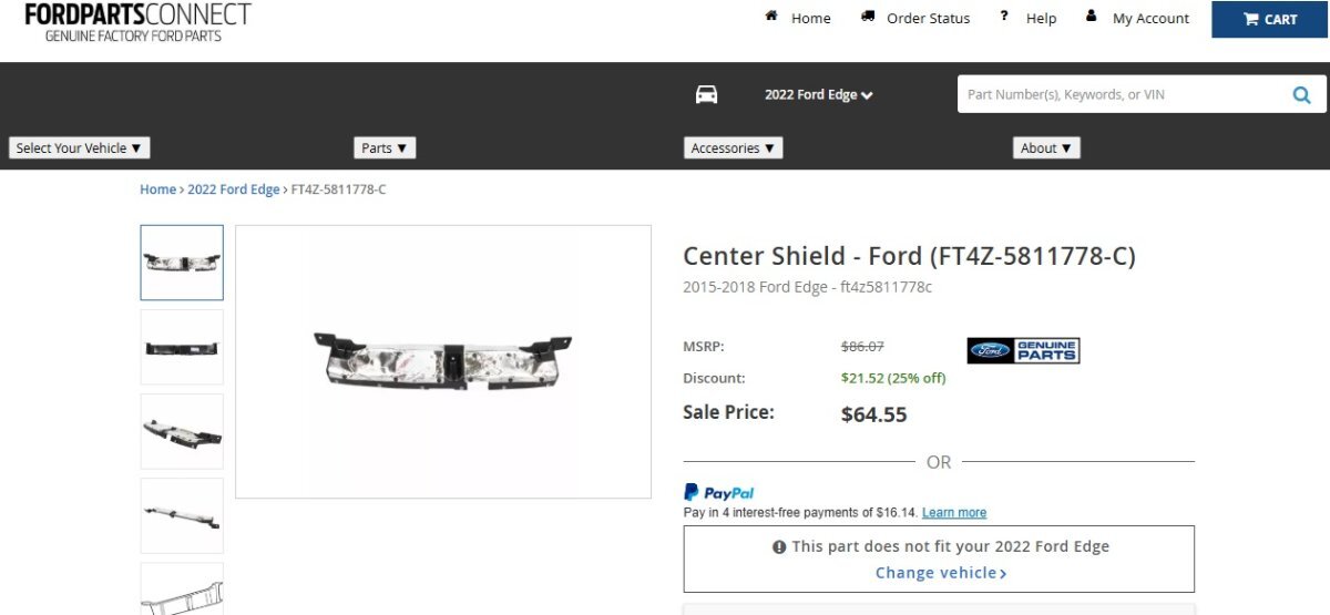
Welcome to the Forum @GoBlueVA! As @enigma-2 observes, FordParts Connect does not show the "discontinued" or "unavailable" designations you may have seen on other parts-selling websites... Link to this FordParts Connection webpage Be aware that the "This part does not fit your 2022 Edge" warning is due to the Ford's discontinuing factory installation of the part. Because other online parts-sellers using the RevolutionParts website infrastructure show the part as "discontinued" or "unavailable", you may want to telephone FordParts Connection to ensure they have access to the part, since they do not show it as "In Stock"... As an alternative, you may want to use the Forum Messaging feature to contact Forum member @rafeeki to see if the two of you can work something out... Good luck!

-
Replaced rear driver side tire today. 2018 Titanium
Haz replied to flymore's topic in All Wheel Drive (AWD)
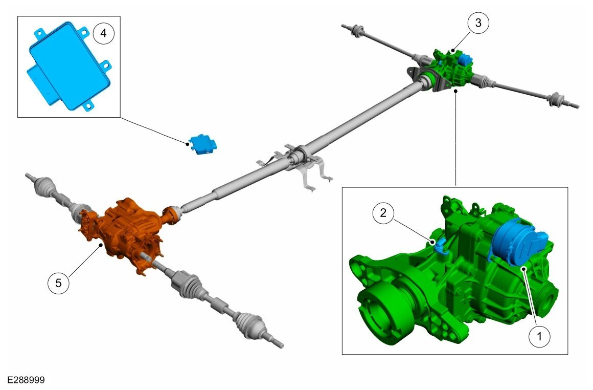
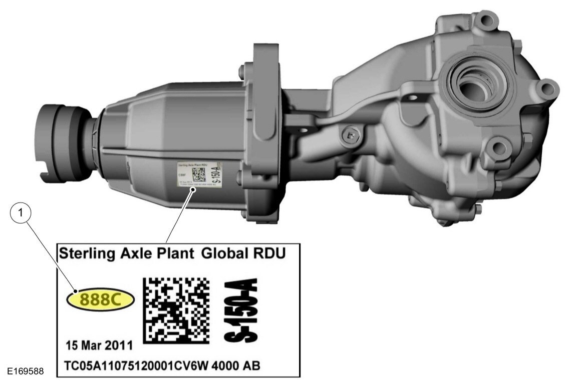
From the 2019 Edge Workshop Manual... Placing your device cursor over underlined acronyms may yield popup whole word descriptions of the acronyms. RDU The RDU contains an actuator motor, ball ramp, position speed sensor and a multi-plate clutch pack. The position/speed sensor mounted on RDU is reading the ring gear speed. The RDU position/speed sensor provides the information of drive shaft speed and its position. The RDU signals are accessible on the CAN bus via the AWD module. The PTU (Power transfer unit) is a gearbox that attaches to the transmission. It directs power from the transmission differential case through a dog clutch to a hypoid ring gear which is splined to the output flange. When the dog clutch is released, no torque is transferred to the rear driveshaft. When the dog clutch is applied, up to 50% of transmission differential case torque may be transferred to the rear driveshaft. The RDU and PTU (Power transfer unit) interface receive direction from the AWD module. The AWD system continuously monitors vehicle conditions and automatically adjusts the torque distribution between the front and rear wheels. During normal operation, most of the torque is delivered to the front wheels. Both the PTU (Power transfer unit) dog clutch and RDU multi-plate clutches are disengaged and the drive shaft does not rotate in the normal operation. When vehicle require AWD operation, the AWD module commands the RDU to engage the multi-plate clutch, which in turn engages the rear differential to rotate the drive shaft. When the drive shaft's speed is within 30 RPM of the front axle, based on RDU speed sensor which is reading ring gear speed, the AWD module commands the PTU (Power transfer unit) dog clutch to engage, transferring torque to all 4 wheels. The system will then apply or release the RDU clutch pack when necessary depending on road conditions. The AWD system may be referred to as a 4WD system in other service information and owner literature or messages located on the message center. The AWD system is an active system, which means it not only responds to wheel slip between the front and rear axles but also has the ability to anticipate wheel slip and transfer torque to the rear wheels before the slip occurs. The AWD system is active all the time and requires no input from the operator. The RDU is an open differential with electronically controlled clutch pack system. The RDU system vary the amount of torque to the rear axle by controlling the actuator motor by following modes: Economy Mode: During normal FWD operation, both clutches are disengaged and the differential allows the drive shaft to freewheel without transmitting torque to either wheel. Connect Mode: When the vehicle controller determines that the AWD system function may be needed, the AWD module commands the RDU actuator motor to start to engage. The RDU clutch will reach the “touch point” when the driveshaft starts to turn. The AWD module then backs off the RDU clutch, and slowly applies the clutch until driveshaft speed is within 30 RPM of the front axle speed. Torque Mode: When the vehicle is in torque mode, the AWD then commands the PTU (Power transfer unit) to engage. The shift fork moves and slides the collar to engage the dog clutch. The PTU (Power transfer unit) reports back the position of the shift fork to the AWD module. When the PTU (Power transfer unit) is fully engage and the driveshaft is moving with the front axle, the RDU is then commanded to engage the clutch as necessary for the AWD operation. In this mode ,the rear differential is driven and provides torque as part of the AWD system. Rear Drive Axle and Differential - Component Location Item Description 1 RDU actuator motor 2 Speed sensor 3 RDU 4 AWD module 5 PTU (Power transfer unit) From the 2018 Edge Workshop Manual... Spare Tire And Mismatched Tire Sizes If the spare tire is installed, the AWD system may disable automatically and enter FWD only mode to protect driveline components. If the AWD systems detects 1 tire is 5% larger or smaller than the other tires, it may also disable the AWD system. This condition may be indicated by AWD OFF message in the message center. If there is a Check AWD message in the message center from using the spare tire, this indicator should turn off after reinstalling the repaired or replaced normal road tire and cycling the ignition OFF and ON. It is recommended to reinstall the repaired or replaced road tire as soon as possible. Major dissimilar tire sizes between the front and rear axles could cause the AWD system to stop functioning and default to FWD or damage the AWD system. If this condition occurs, a DTC is set and a Check AWD message is displayed on the message center. Four-Wheel Drive Systems - Overview NOTE: The AWD system may be referred to as a 4WD system or Active Torque Coupling (ATC) system in other service information, owner literature, or messages located on the message center. The AWD system consists of the following: Power Transfer Unit (PTU) Rear halfshafts Driveshaft AWD relay module Rear Drive Unit (RDU) Active Torque Coupling (ATC) solenoid PCM for system control logic The AWD system is an active system, which means it not only responds to wheel slip between the front and rear axles but also has the ability to anticipate wheel slip and transfer torque to the rear wheels before the slip occurs. The AWD system is active all the time and requires no input from the operator. The AWD system continuously monitors vehicle conditions and automatically adjusts the torque distribution between the front and rear wheels. During normal operation, most of the torque is delivered to the front wheels. If wheel slip between the front and rear wheels is detected, the vehicle is under heavy acceleration or if the vehicle is in a handling event, the AWD system increases the duty cycle to the Active Torque Coupling (ATC) solenoid. The ATC solenoid engages a pilot clutch in the Rear Drive Unit (RDU) which in turn sets a ball ramp device in motion. The ball ramp device applies the main clutch pack in the RDU and increases torque to the rear wheels as necessary. When the AWD system is functioning properly, there should be no perceived speed difference between the front and rear axles when launching or driving the vehicle on any uniform surface. Traction should be similar to a part time 4WD system operating in 4H (4X4 HIGH), but have no binding in turns. Automatic Torque Coupling Configuration Bar Code Label Location Component Description PCM The PCM is the logic module for the four-wheel drive system. Multiple modules/system inputs are used for the four-wheel drive system to determine the percentage of torque to be transferred to the rear wheels. Transfer Case The transfer case is a gearbox that attaches to the transmission. The transfer case directs power to the rear driveshaft and the Rear Drive Unit (RDU). AWD Relay Module The AWD relay module receives the command from the PCM , and in turn supplies a PWM output to the Automatic Torque Coupling (ATC) solenoid for the requested torque to be applied. Automatic Torque Coupling (ATC) Solenoid The Automatic Torque Coupling (ATC) solenoid applies clutch pressure as controlled by the AWD relay module to increase or decrease torque to the rear wheels. The Rear Drive Unit (RDU) transfers torque from the drive shaft to the rear differential depending on the specific request from the FWD system module ( PCM ). Good luck!

-
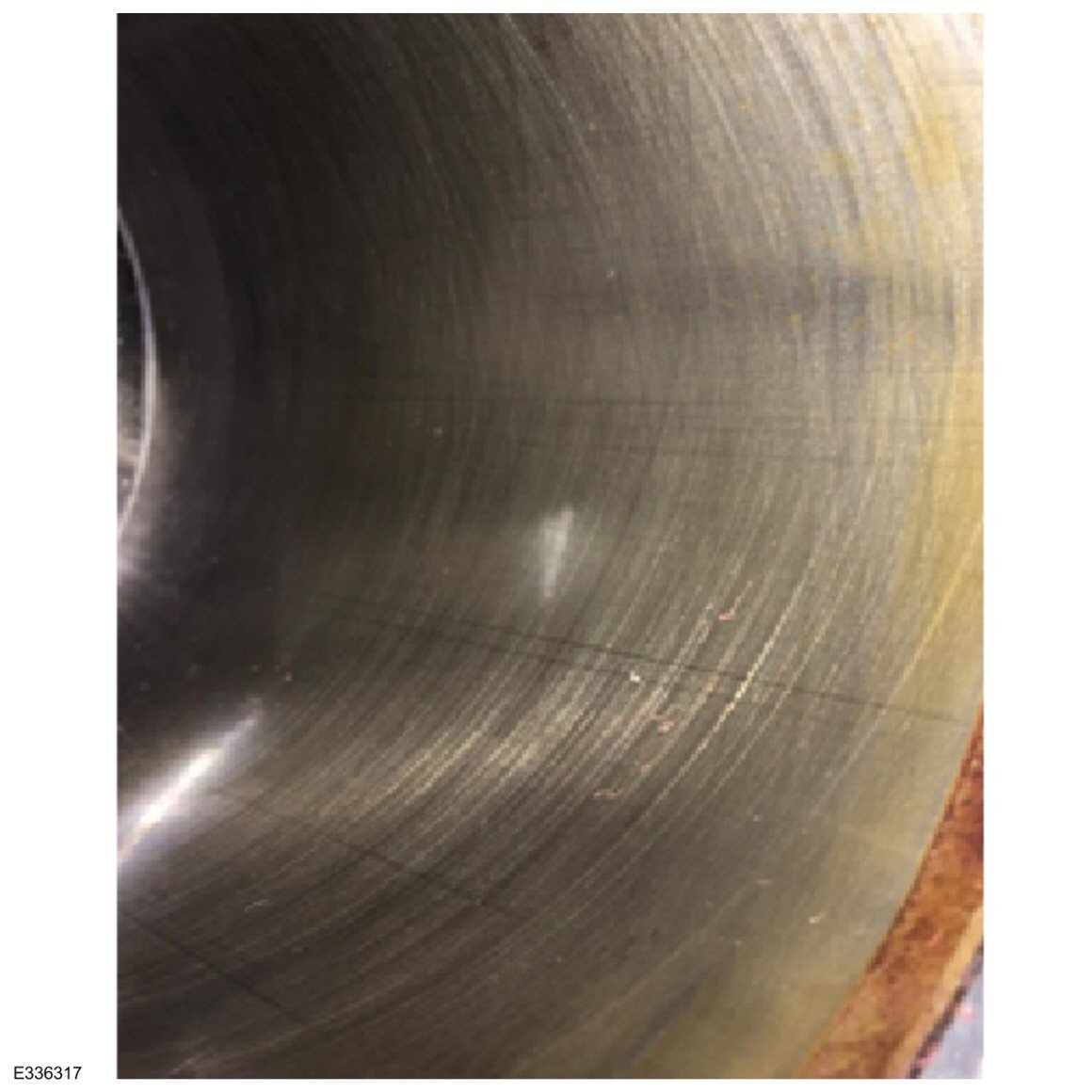
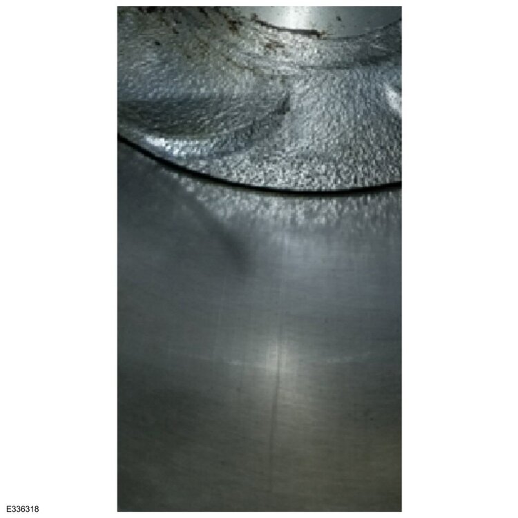
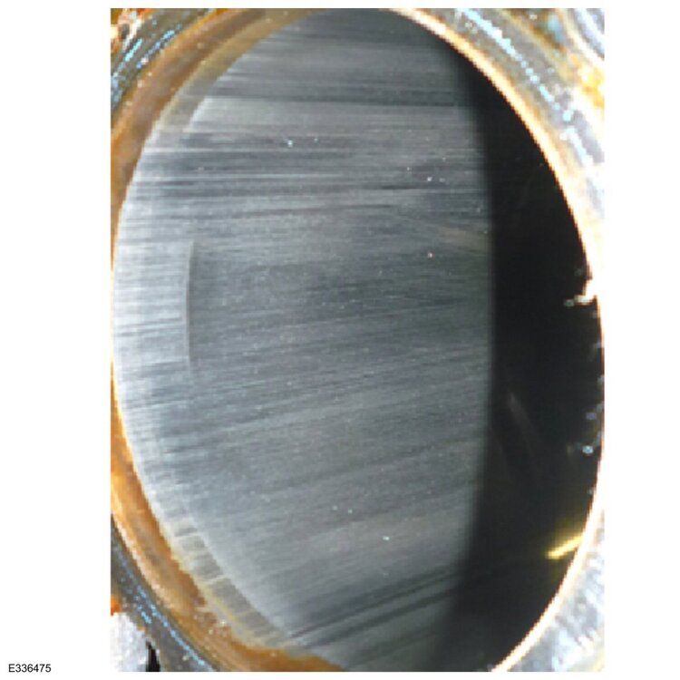
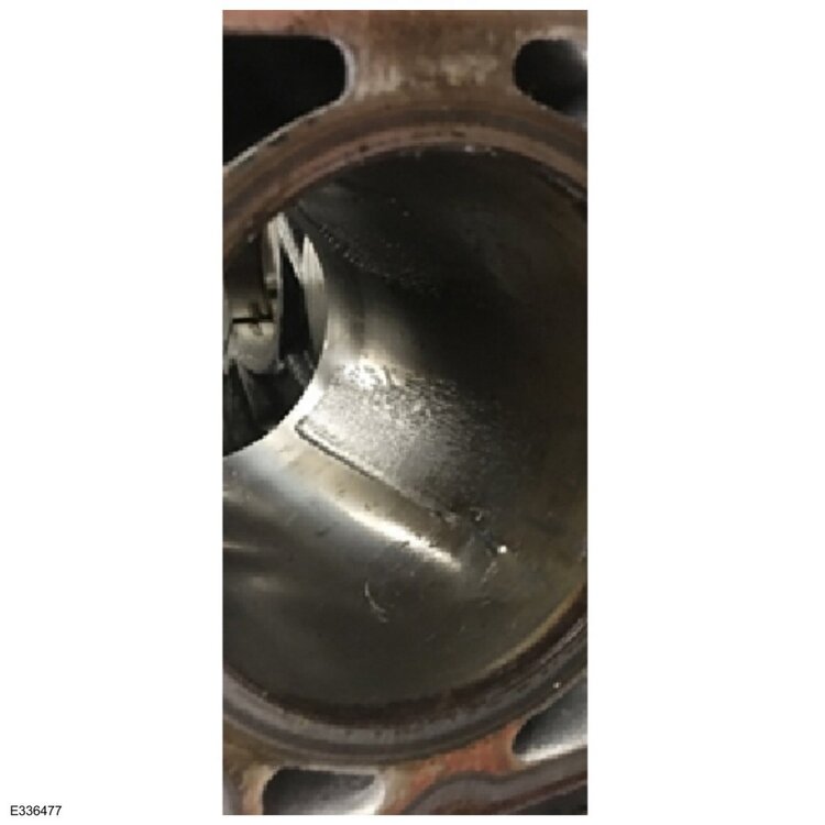
GENERAL SERVICE BULLETIN Various Vehicles - Engine Failure Analysis 22-7078 23 May 2022 This bulletin supersedes 20-7062. Summary This article supersedes GSB 20-7062 to update the vehicle model years affected. This bulletin is a guide to engine failure analysis and preventing repeat engine failure. Service Information Determining Root Cause Understanding normal engine wear vs. actual engine damage can increase the accuracy of determining the root cause. If the true root cause of the engine failure is not identified with visual confirmation, an over repair or incomplete repair leading to repeat engine failure may result. Root cause determination and the extent of engine damage is necessary during engine assessment. Inspection areas include: • Oil filter • Oil pan • Cylinder head and deck surfaces • Camshaft bores, journals and lobes • Crankshaft journals • Cylinder walls and piston skirts • Rod and main bearings Engine Analysis Metal in the Oil Pan, Filter and/or Screens – Acceptable Conditions Some metal in the oil pan and filter is expected and considered normal (Figures 1-2). Figure 1 Figure 2 Some metal shavings in the oil filter are not a concern (Figure 3). Figure 3 Small specs of metal in the filter media is normal (Figure 4). Figure 4 Assembly paint is not a concern. Do not confuse with bearing material. Metal in the Oil Pan, Filter and/or Screens – Unacceptable Conditions Large chunks of metal in the pan and/or filter merit further root cause investigation (Figures 5-6). Figure 5 Figure 6 Excessive amounts of metal in the oil filter and/or screens require further root cause investigation (Figures 7-8). Figure 7 Figure 8 Camshaft Bore, Journal and Lobe Inspection Cam Bore – Normal Wear: Polishing, discoloration, slight porosity or minor scoring (Figures 9-10). Figure 9 Figure 10 Cam Bore – Damage: Material loss, deep scoring and severe porosity (Figures 11-12). Figure 11 Figure 12 Camshaft Journals and Lobes - Normal Wear: Polishing, discoloration, minor uniform scoring felt with a fingernail (Figures 13-15). Figure 13 Figure 14 Figure 15 Camshaft Journals and Lobes – Damage: Material loss/transfer, deep scoring or bluing of the metal are all signs of damage (Figures 16-18). Figure 16 Figure 17 Figure 18 Crankshaft and Bearing Inspection Bearings – Normal Wear: Polishing, discoloration, light scoring, light contact with red coating (Figures 19-22). Figure 19 Figure 20 Figure 21 Figure 22 NOTE: Bearings are designed to manage some debris; therefore, some light scoring found on the bearing surface is not necessarily an indication of engine failure or root cause determination. Bearings – Damage: Metal transfer, erosion, material loss, coolant contamination, deep scoring, cracking, spun bearing (Figures 23-27). Figure 23 Figure 24 Figure 25 Figure 26 Figure 27 Crankshaft – Normal Wear: Discoloration, polishing, light scratches (Figures 28-29). Figure 28 Figure 29 Crankshaft – Damage: Material loss, deep scoring, material transfer (Figures 30-32). Figure 30 Figure 31 Figure 32 Head and Block Surface Inspection Head and Block Surface – Normal Wear: Porosity outside sealing surfaces, gasket surface discoloration, light scratches (Figures 33-34). Figure 33 Figure 34 Head and Block Surface – Damage: Porosity on sealing surfaces, deep gouges, material transfer, warpage (Figures 35-37). Figure 35 Figure 36 Figure 37 Cylinder Wall and Piston Skirt Inspection Cylinder Wall – Normal Wear: Slight polishing and/or discoloration, vertical streaking, slight scoring, cross hatch present, light staining (Figures 38-40). Figure 38 Figure 39 Figure 40 Cylinder Wall – Damage: Deep gouging, impact marks, loss of crosshatch, cracks (Figures 41-43). Figure 41 Figure 42 Figure 43 Piston Skirt – Normal Wear: Light wear of the coating (Figures 44-45). Figure 44 Figure 45 Piston Skirt – Damage: Deep scoring, severe coating wear (Figure 46-47). Figure 46 Figure 47 Preventing Repeat Engine Failures Identifying certain failure modes such as detonation, running lean, oil consumption and/or hydro-locking will help determine if further inspection of components is required to prevent repeat failures. Piston and Cylinder Wall Damage Root Cause: Lean conditions or modifications (Figures 48-49) Figure 48 Figure 49 • Modifications (timing, CNG, incorrect spark plugs) - Overboost (supercharger/turbocharger) - PCM performance chip/programmer • Lean conditions - Mass air flow (MAF) sensor failure - Damaged air intake Effect: High cylinder pressure or spark knock • Excessive combustion temperatures • Excessive cylinder pressure • Pre-ignition • Excessive levels of detonation (low octane/poor fuel quality) Damage: Piston and cylinder wall • Spark plug electrode damage • Hole in piston (pre-ignition) • Piston ring land damage (detonation) • Pitted piston face • Cylinder wall scoring Spark plug damage (porcelain fracture or melted electrode) is an indication of excess detonation (Figure 50) Figure 50 Heat generated from friction can cause cylinder walls to crack. (upper ring land damage) (Figure 51) Figure 51 Excess detonation causes excess cylinder pressure spikes leading to piston ring land fractures (second ring land is damaged). (Figure 52) Figure 52 Cylinder Wall Damage (Figure 53) Figure 53 Root Cause: Fuel/air mixture concerns • Excess oil consumption • Lean/rich conditions • Cylinder misfire Effect: Catalyst damage • Catalyst material begins to deteriorate (turns to dust/sand) • Catalyst material is pulled into the engine Damage: Cylinder wall • Cross hatch is polished away • Vertical scoring • Bearing damage may be present if catalyst material made it to the engine oil. Check for catalyst debris by shaking out the converter onto a clean surface (Figure 54) Figure 54 Catalyst material can collect on the sides of the piston damaging cylinder wall surfaces (Figure 55) Figure 55 Valve Damage (Figures 56-57) Figure 56 Figure 57 Root Cause: Lean condition • Modification or damage to the air induction system • MAF sensor damage/failure • Lack of fuel to the cylinder Effect: Excessive combustion chamber temperatures • Misfire, lacks power • Catalyst damage • Running lean = hot cylinder Damage: Valve and valve seat • Valve tuliping • Valve seat recession (Figure 58) Figure 58 If cylinder leakage is present past the valves: • Check for valves held open by other valvetrain components • Check for the valve stem sticking in the guide • Inspect for debris between the valve and seat that could hold the valve open Excessive lean conditions can cause valves to overheat and soften. Over time, the valve can stretch and deform against the seat causing the valve to “tulip” creating leakage and a misfire. Comparing total valve height of the suspect valve to a known good valve can help identify issues. A height difference in the suspect valve is an indication of valve tuliping. Valve tuliping is the effect, not the root cause of the concern. Foreign Object Debris (Figure 59) Figure 59 Root Cause: Combustion chamber damage • Broken piston/rings • Broken valves • Dropped valve seats Effect: Debris transfer • Original intake manifold transferred to the new engine • Intake manifolds cannot be cleaned in these instances and require replacement Damage: Repeat engine failure • Engine vacuum dislodges debris left in the manifold • Debris will enter the combustion chamber and cause piston/cylinder damage (Figure 60) Figure 60 • Foreign object debris can cause metal transfer from the piston to the cylinder head • This metal debris can also make it to the intake manifold • The intake manifold must be replaced in these instances to prevent repeat damage Bearing Damage (Figure 61) Figure 61 Root Cause: PCV system concerns • PCV system damaged • Open breather tube in place of PCV valve • Lack of oil maintenance Effect: Oil consumption • Oil is pulled through the engine and burned off Damage: Bearing damage • Bearing and journal damage from lack of lubrication • An open breather tube fitting mistaken for a PCV valve could be transferred to the new engine leading to repeat bearing failure (Figure 62). During engine replacement, verify the PCV valve is operational and correct for the application. Figure 62 NOTE: Remanufactured Modular 2V V8 and V10 engines do not come with a PCV valve installed. If there appears to be a valve/tube in place on a new Remanufactured 2V V8 or V10 engine, replace it. Bent Connecting Rod (Figure 63) Figure 63 Root Cause: Hydrolocking from liquid ingestion • Leaking or stuck open fuel injector • Water ingestion through the air inlet (wet, warped or damaged air filter) Effect: Hydrolocking • Liquid cannot be compressed and will prevent the piston from traveling to top dead center (TDC) Damage: Connecting rod • Connecting rod will bend or break • May occur on more than one cylinder (Figures 64-65) Figures 64 Figure 65 • Since fluids cannot be compressed, the connecting rod typically suffers from a hydrolock event. © 2022 Ford Motor Company All rights reserved. NOTE: This information is not intended to replace or supersede any warranty, parts and service policy, workshop manual (WSM) procedures or technical training or wiring diagram information.
-
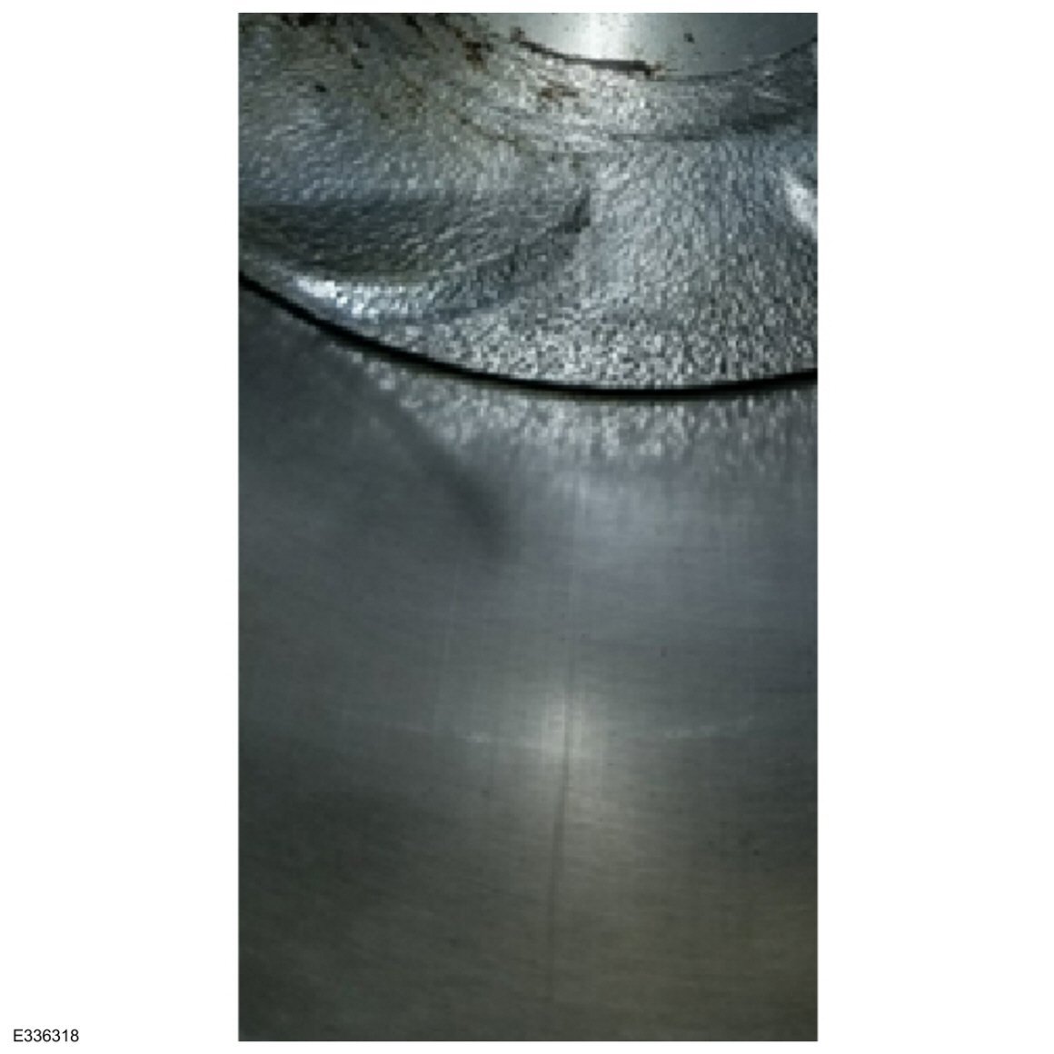
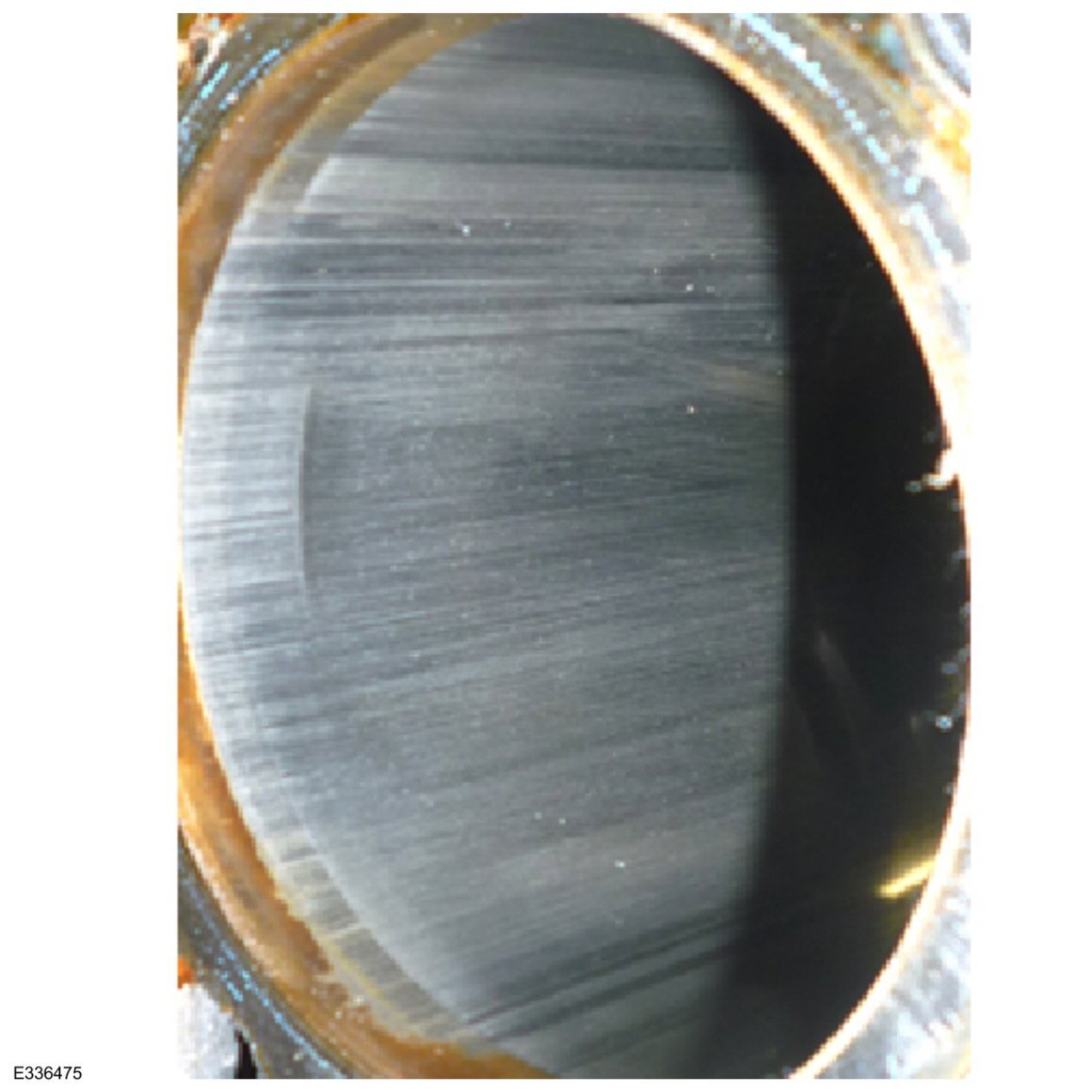
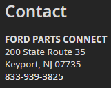
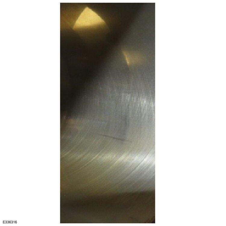
** TSB 24-2384 has been superceded by TSB 25-2074, which is posted immediately below ** TECHNICAL SERVICE BULLETIN Misfire With DTCs P0301, P0302, P0303, And/Or P0304 Stored In The PCM 24-2384 20 November 2024 Model: Ford 2023-2025 Escape Engine: 1.5L EcoBoost Engine: 2.0L EcoBoost 2025 Explorer Engine: 2.3L EcoBoost 2024 Mustang Engine: 2.3L EcoBoost Lincoln 2023-2025 Corsair Engine: 2.0L EcoBoost 2024-2025 Nautilus Engine: 2.0L EcoBoost Engine: 2.0L EcoBoost Hybrid Markets: North American markets only Issue: Some 2023-2025 Escape/Corsair vehicles equipped with a 1.5L or 2.0L EcoBoost engine, 2024 Mustang vehicles equipped with a 2.3L EcoBoost engine, 2024-2025 Nautilus, and 2025 Explorer vehicles equipped with a 2.3L EcoBoost engine may exhibit an engine misfire condition with DTCs P0301, P0302, P0303 and/or P0304 set in the PCM. To correct this condition, follow the Service Procedure to diagnose the vehicle. Action: Follow the Service Procedure to correct the condition on vehicles that meet all of the following criteria: • One of the following vehicles: - 2023-2025 Escape/Corsair - 2024 Mustang - 2024-2025 Nautilus - 2025 Explorer • One of the following engines: - 1.5L EcoBoost - 2.0L EcoBoost - 2.0L EcoBoost Hybrid - 2.3L EcoBoost • Exhibits an engine misfire condition with any of the following DTCs stored in the PCM: P0301, P0302, P0303 and/or P0304 Warranty Status: Information Only. Repair/Claim Coding Causal Part: IN Condition Code: -1 Service Procedure NOTE: This article is for information only. Determine the causal part number and use available labor times in the SLTS Manual or claim M-time in accordance with the Warranty and Policy Manual. Causal part number IN in this article refers to the information only status and is not able to be claimed. 1. Remove and inspect the condition of all spark plugs. Refer to the WSM, Section 303-07. Are any spark plugs damaged? (1). Yes - proceed to Step 2. (2). No - this article does not apply, replacement of the spark plugs is not necessary, proceed with normal diagnostics found in the WSM. 2. Inspect the 12v battery positive and negative terminals for a loose condition, refer to WSM, Section 414-01 and repair as necessary. 3. Inspect all PCM ground circuitry for loose connections and/or high resistance and repair as necessary. 4. Use a borescope to inspect the condition of the affected pistons and cylinder walls. Refer to Figures 1-3 for examples of normal cylinder wall wear and Figures 4-5 for examples of damaged cylinder walls. Additional examples of engine wear can be found in the Engine Failure Analysis GSB > Cylinder Wall and Piston Skirt Inspection. Do the pistons and/or cylinder walls appear to be damaged? Figure 1 - Showing normal cylinder wall wear Figure 2 - Showing normal cylinder wall wear Figure 3 - Showing normal cylinder wall wear Figure 4 - Showing a damaged cylinder wall Figure 5 - Showing a damaged cylinder wall (1). Yes - remove the cylinder head to perform a more detailed inspection of the suspect damage. Refer to the Engine Failure Analysis GSB > Cylinder Wall and Piston Skirt Inspection and repair as necessary. For cylinder head removal, refer to the WSM, Section 303-01. (2). No - perform a compression test and cylinder leakage test following WSM, Section 303-00 and repair as necessary. 5. Replace all damaged spark plugs. Do not discard the damaged spark plugs so Ford can retrieve them following the warranty parts return process. 6. Submit a GCR and include photos of damaged components, images from the borescope analysis and anything else of interest that was found during the repair. These images will help improve engine quality for future model vehicles. © 2024 Ford Motor Company All rights reserved. NOTE: The information in Technical Service Bulletins is intended for use by trained, professional technicians with the knowledge, tools, and equipment to do the job properly and safely. It informs these technicians of conditions that may occur on some vehicles, or provides information that could assist in proper vehicle service. The procedures should not be performed by "do-it-yourselfers". Do not assume that a condition described affects your car or truck. Contact a Ford or Lincoln dealership to determine whether the Bulletin applies to your vehicle. Warranty Policy and Extended Service Plan documentation determine Warranty and/or Extended Service Plan coverage unless stated otherwise in the TSB article. The information in this Technical Service Bulletin (TSB) was current at the time of printing. Ford Motor Company reserves the right to supersede this information with updates. The most recent information is available through Ford Motor Company's on-line technical resources. TSB 24-2384 - Misfire With DTCs P0301, P0302, P0303, And Or P0304 Stored In The PCM.pdf
- 1 reply
-
- 2
-

-
2016 Edge Sport Alternator Job - Anyone have details?
Haz replied to Cerberus's topic in 2016 Edge & MKX
@sosaudio1: Ford's parts-selling website search result, based upon your Edge's VIN = Motorcraft Part # GL8783 / Ford Part # F2GZ10346B... Link to this FordParts page Good luck!
-
On November 11th, @Renegadebuck offered the following reply to my questions about the experience, via Forum messaging... It does have ACC, and it was on. Yes, the wheel jerked left while I was holding it. I don’t remember hearing or seeing a warning. I don’t remember the [ABS] brake pump sound working, but I had the radio on and wasn’t expecting anything to happen. I had to mash the accelerator to the floor to keep it from completely stopping, and when it started accelerating everything went back to normal. Completely dry and straight road. I have not checked [for DTCs] with a scanner. Good luck!
-
With emphasis added... Ford Co‑Pilot360 Assist+ Evasive Steering Assist Evasive Steering Assist(1) aids the driver in avoiding a collision with a slower or stopped vehicle ahead by providing a boost to the steering. This allows the driver to steer with less effort when the collision cannot be avoided by braking alone. Dramatization. How It Works Designed to operate at city and highway speeds Detects slower-moving and stationary vehicles ahead by using a camera and radar Analyzes the gap between vehicles and classifies the risk of having a rear-end collision If the risk is high and there is insufficient space to avoid a collision by braking only, the system provides the appropriate level of steering torque to help the driver steer around the obstacle How To Use If there is a slowed or stopped vehicle ahead, the system only activates when all of the following occurs: Pre-Collision Assist detects a vehicle ahead and starts to apply Active Braking The driver turns the steering wheel in an attempt to steer around the vehicle and the system applies additional steering torque to help steer around the vehicle After the vehicle is passed, the system applies steering torque in the opposite direction to encourage the driver to steer back into the lane. It applies the brakes of individual wheels to enhance path-following capability The system deactivates after the vehicle is fully passed If the system is not operating properly, ensure the sensors are clean from debris such as snow or mud NOTE: Evasive Steering Assist does not automatically steer around a vehicle. If the driver does not turn the wheel, the system will not activate. NOTE: When Active Braking is turned Off, Evasive Steering Assist is also turned Off. Both features automatically turn On at each key cycle. (1) Evasive steering does not control steering. DRIVER-ASSIST NOTE: Driver-assist features are supplemental and do not replace the driver’s attention, judgment and need to control the vehicle. It does not replace safe driving. See Owner’s Manual for details and limitations.

-
2016 Edge Sport Alternator Job - Anyone have details?
Haz replied to Cerberus's topic in 2016 Edge & MKX
@sosaudio1: Relevant 2017 Edge Workshop Manual sections are attached below as PDF documents... Good luck! Climate Control System Specifications - General Information - 2017 Edge Workshop Manual.pdf Electronic Leak Detection - General Procedures - 2017 Edge Workshop Manual.pdf Fluorescent Dye Leak Detection - General Procedures - 2017 Edge Workshop Manual.pdf Refrigerant System Tests - 2.7L EcoBoost - General Procedures - 2017 Edge Workshop Manual.pdf Refrigerant Oil Adding - General Procedures - 2017 Edge Workshop Manual.pdf Climate Control Tools and Equipment - General Procedures - 2017 Edge Workshop Manual.pdf Refrigerant Identification Testing - General Procedures - 2017 Edge Workshop Manual.pdf Air Conditioning (A-C) System Recovery, Evacuation and Charging - General Procedures - 2017 Edge Workshop Manual.pdf Air Conditioning (A-C) System Flushing - General Procedures - 2017 Edge Workshop Manual.pdf Air Conditioning (A-C) Compressor - 2.7L EcoBoost - Removal and Installation - 2017 Edge Workshop Manual.pdf Generator - 2.7L EcoBoost - Removal and Installation - 2017 Edge Workshop Manual.pdf -
The following 2022-2024 Edge Workshop Manual sections, attached below as PDF documents, describe the operation and components of the Adaptive Cruise Control System Lane Keeping/Lane Centering System, and Collision Warning/Collision Avoidance System Good luck! Adaptive Cruise Control - System Operation and Component Description - 2022 Edge Workshop Manual.pdf Adaptive Cruise Control - Pre-Collision Assist - 2022 Edge Workshop Manual.pdf Lane Keeping System - Overview - Description and Operation - 2022 Edge Workshop Manual.pdf Lane Keeping System - System Operation and Component Description - 2022 Edge Workshop Manual.pdf Collision Warning and Collision Avoidance System - System Operation and Component Description - 2022 Edge Workshop Manual.pdf
-
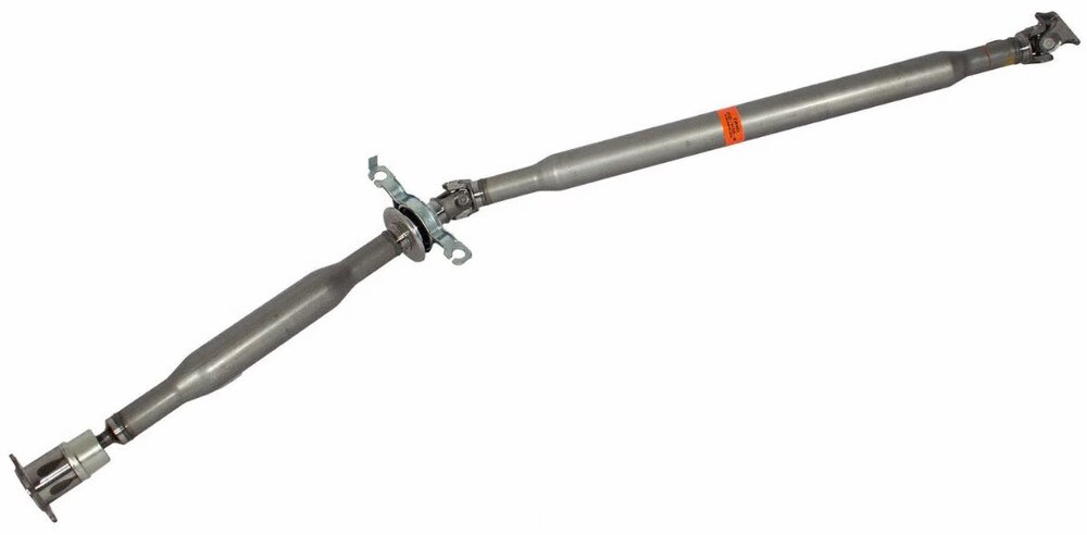
Anyone replace their DriveShaft on their Edge?
Haz replied to Spprtmechanic's topic in 2010 Edge & MKX
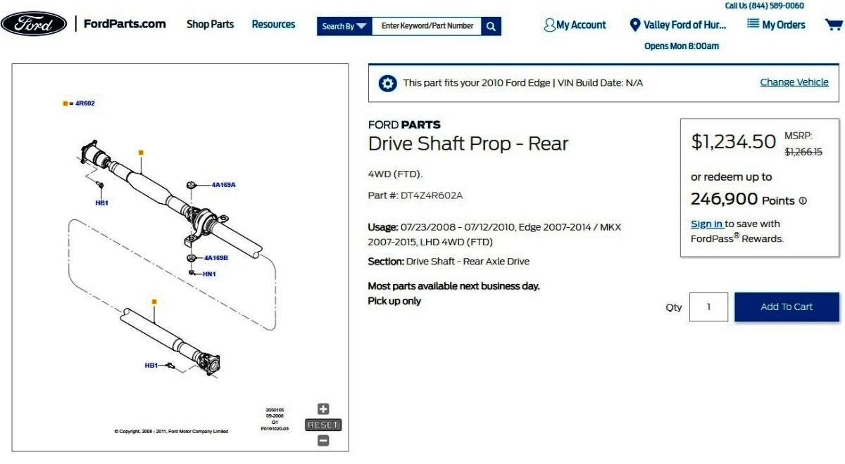
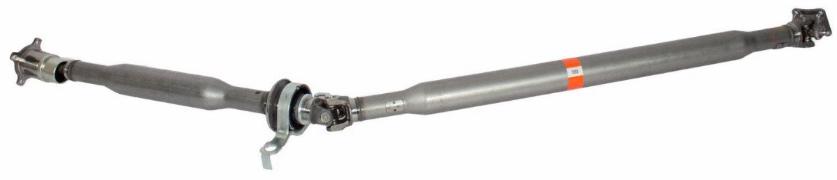
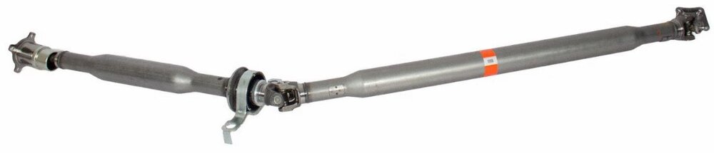
Entering your pictured Driveshaft part number into Ford's parts-selling website yields the Service part number your dealer cited... Link to this FordParts webpage From the 2010 Edge Workshop Manual, below, with Driveshaft replacement procedure attached as PDF document... Good luck! Driveshaft NOTE: All driveshaft assemblies are balanced. If undercoating the vehicle, protect the driveshaft to prevent overspray of any undercoating material. The driveshaft assembly consists of the following: Rubber isolated center support bearings CV joint at the Power Transfer Unit (PTU) U-joints at the center support and pinion flange Assembly balanced with traditional balance weights Lubed-for-life joints requiring no periodic lubrication The driveshaft transfers torque from the PTU to the rear axle. It is attached to the PTU flange with a CV joint. The driveshaft is connected by a staked U-joint at the center bearing and attached to the rear pinion flange. The driveshaft joints allow the smooth continuous rotation of the driveshaft through the allowable angle planes and length variations required in normal vehicle operation. The driveshaft is always turning at front wheel speed. The driveshaft is not serviceable. A new driveshaft must be installed if worn or damaged. AWD Driveshaft - Removal and Installation - 2010 Edge Workshop Manual.pdf
-
2016 Edge requires new wheel hub to replace broken stud?
Haz replied to Raycaster's topic in Brakes, Chassis & Suspension
Regardless of this Wheel Hub's AWD descriptor, using the VIN of a 2016 FWD Edge on Ford's parts-selling website resolves it as fitting FWD also... Link to this FordParts webpage Perhaps the following high-resolution (1500 x 1500) FordParts-linked images can reconcile your question with the Mechanic's comment... Good luck!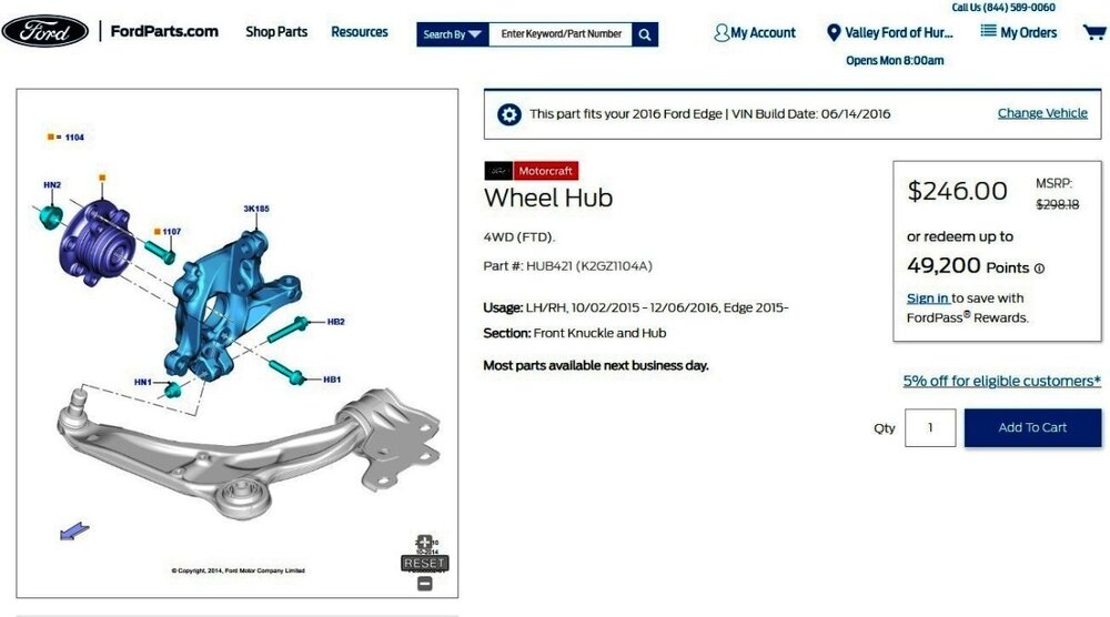
-
Attention - there's an uptick in accounts being hacked
Haz replied to 1004ron's topic in Forum Help & Site Suggestions
Sounds like it's time, once again, to change my randomized 20-character password... Good luck!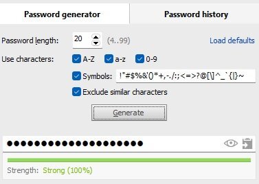
-
2016 Edge requires new wheel hub to replace broken stud?
Haz replied to Raycaster's topic in Brakes, Chassis & Suspension
Per the 2016 Edge Workshop Manual, Wheel Studs are a replaceable part in Front & Rear hubs... Good luck! Wheel Studs - Removal and Installation - 2016 Edge Workshop Manual.pdf Front Wheel Bearing and Wheel Hub - Removal and Installation - 2016 Edge Workshop Manual.pdf Rear Wheel Bearing and Wheel Hub - FWD - Removal and Installation - 2016 Edge Workshop Manual.pdf Brake Disc - Removal and Installation - 2016 Edge Workshop Manual.pdf -
The original Forum announcement with Dealer Bulletin details... Emission Recall 24E10 - Certain 2015-2018 Edge with 3.5L Engine - Reprogram Powertrain Control Module (PCM) The Owner Letter you received mentions only "2016" because that's the Model Year of your Edge. I expect the "over time" revelation of the problem is why 2015-2018 Edges are now subject to the Recall. I do look forward to your personal assessment of the updated PCM software's affect upon your Edge's drivability! Good luck!

-
HD shocks on rear or rear coil overs for a '14 edge
Haz replied to Steve Hahn's topic in Brakes, Chassis & Suspension
Welcome to the Forum @Steve Hahn! Forum Search: Airlift air spring Good luck! -
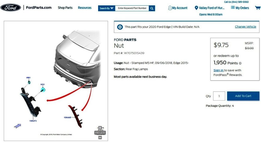
Ford Part # W707501S439, M5 Speed Nut... I expect you may be able to obtain an equivalent Speed Nut in your local hardware store's fastener department for less than $2 each. Good luck!
-
Link to this FordParts webpage
-
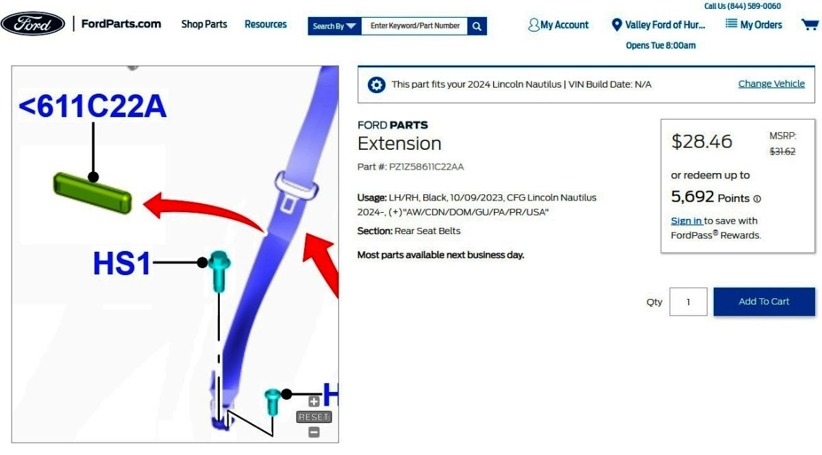
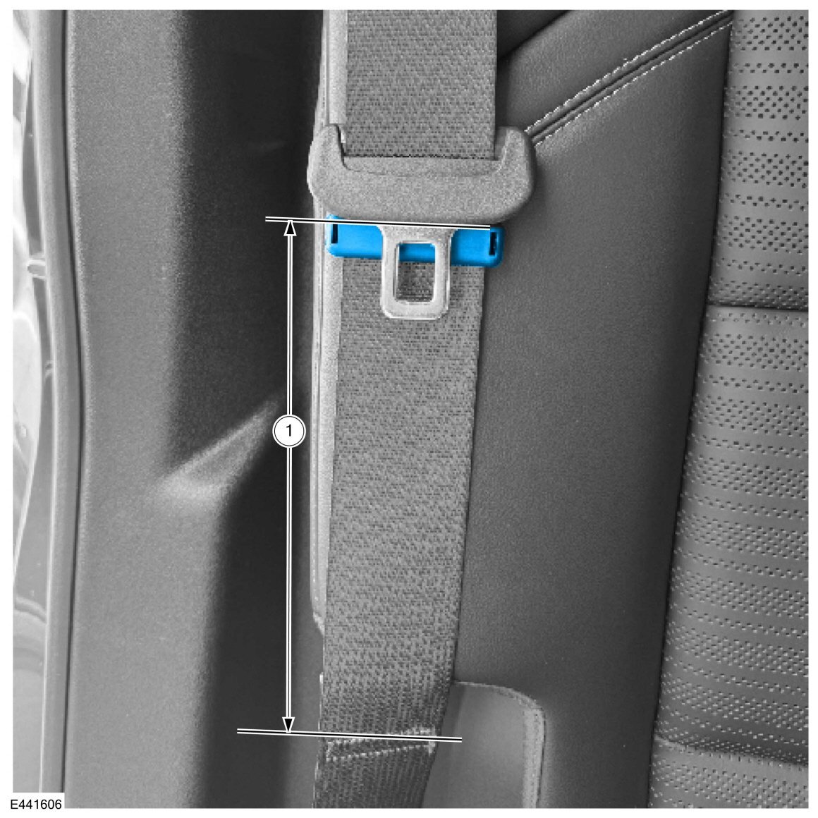
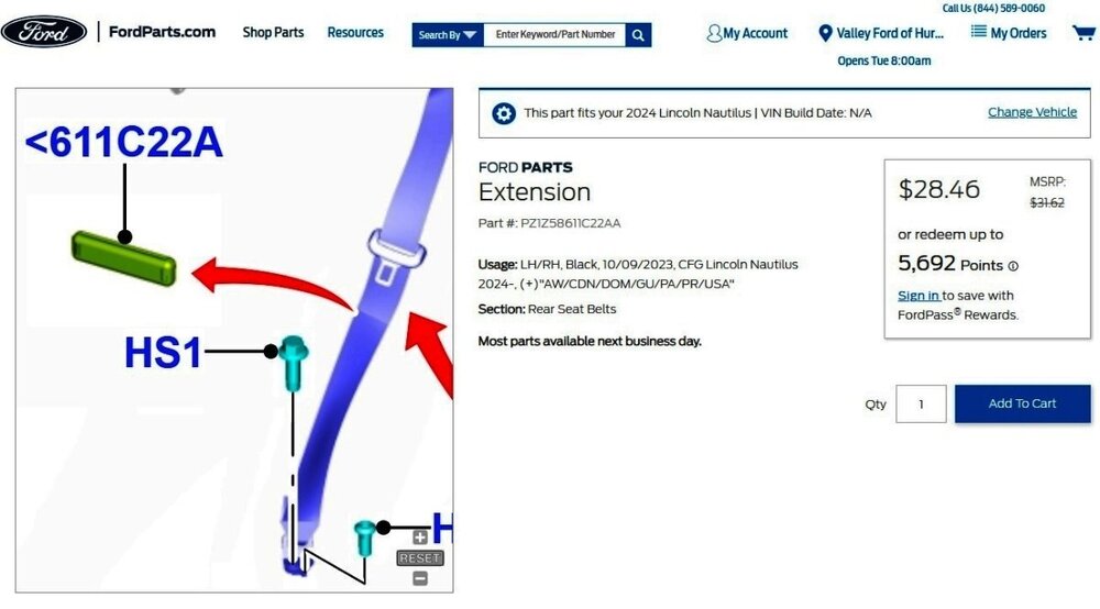
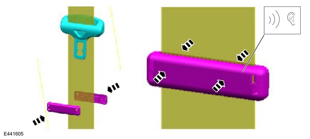
TECHNICAL SERVICE BULLETIN Rear Outboard Seat Belt Tongue Rattle Against Rear Interior Door Panel And/Or C-Pillar - Built On Or Before May 13, 2024 24-2258 08 November 2024 Model: Lincoln 2024 Nautilus Built on or before 13-May-2024 Markets: North American market only Issue: Some 2024 Nautilus vehicles built on or before 13-May-2024 may exhibit a rattle noise from the rear outboard seat area. This may be due to the outboard seat belt tongue making contact with either rear interior door panel and/or C-pillar moulding. To correct this condition, follow the Service Procedure to install a seat belt clip to reposition the seat belt tongue upward. Action: Follow the Service Procedure on vehicles that meet all of the following criteria:• 2024 Nautilus • Built on or before 13-May-2024 • Rear outboard seat belt retractors functioning normally and free of damage • Rear outboard seat belt tongue making contact with either rear interior door panel and/or C-pillar moulding Parts Service Part Number Claim Quantity Package Order Quantity Number in Package Description PZ1Z-58611C22-AA 2 2 1 Seatbelt Clip Claim Quantity refers to the total number of individual pieces required to repair the vehicle. Package Order Quantity refers to the amount of the service part number package(s) required to repair the vehicle. Number In Package refers to the number of individual pieces included in a service part number package. Warranty Status: Eligible under provisions of New Vehicle Limited Warranty (NVLW)/Service Part Warranty (SPW)/Service Part New Vehicle (SPNV)/Extended Service Plan (ESP) coverage. Limits/policies/prior approvals are not altered by a TSB. NVLW/SPW/SPNV/ESP coverage limits are determined by the identified causal part and verified using the OASIS part coverage tool. Labor Times Description Operation No. Time 2024 Nautilus: Install And Adjust Clip On Seatbelt Webbing On Both (2) Sides Following The Service Procedure (Do Not Use With Any Other Labor Operations) 242258A 0.3 Hrs. Repair/Claim Coding Causal Part: 58611C22 Condition Code: 07 Service Procedure 1. Snap together and lock both seat belt clip halves over seat belt. (Figure 1) Figure 1 2. Slide clip and belt tongue upwards together along belt webbing until it contacts the belt tongue, and then upwards approximately 6 in. (150 mm). 3. Confirm the seat belt tongue is now 6 in. (150 mm) higher than the previously stowed position. Adjust seat belt tongue position again if necessary to achieve this distance. (Figure 2) Figure 2 4. Verify the seat belt tongue is now free from contacting either rear interior door panel and/or C-pillar molding. 5. Repeat Steps 1-4 for other side. © 2024 Ford Motor Company All rights reserved. NOTE: The information in Technical Service Bulletins is intended for use by trained, professional technicians with the knowledge, tools, and equipment to do the job properly and safely. It informs these technicians of conditions that may occur on some vehicles, or provides information that could assist in proper vehicle service. The procedures should not be performed by "do-it-yourselfers". Do not assume that a condition described affects your car or truck. Contact a Ford or Lincoln dealership to determine whether the Bulletin applies to your vehicle. Warranty Policy and Extended Service Plan documentation determine Warranty and/or Extended Service Plan coverage unless stated otherwise in the TSB article. The information in this Technical Service Bulletin (TSB) was current at the time of printing. Ford Motor Company reserves the right to supersede this information with updates. The most recent information is available through Ford Motor Company's on-line technical resources. TSB 24-2258 - Rear Outboard Seat Belt Tongue Rattle - 2024 Nautilus - Built On Or Before May 13, 2024.pdf

-
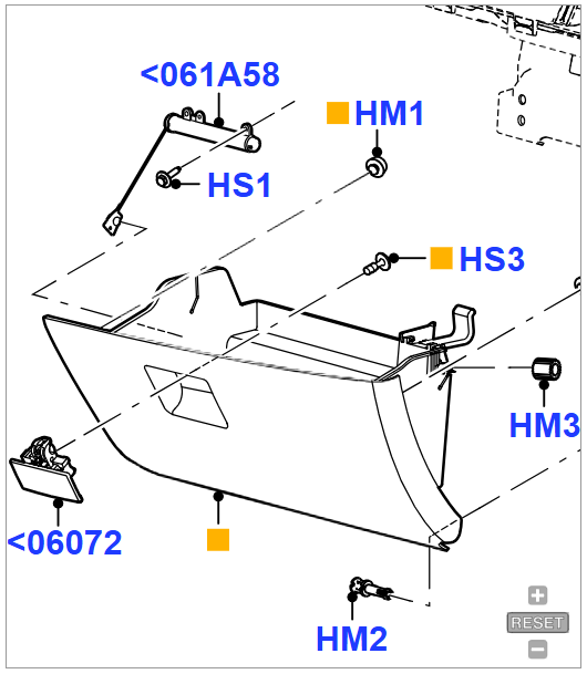
Additional reference imagery... Good luck!


-
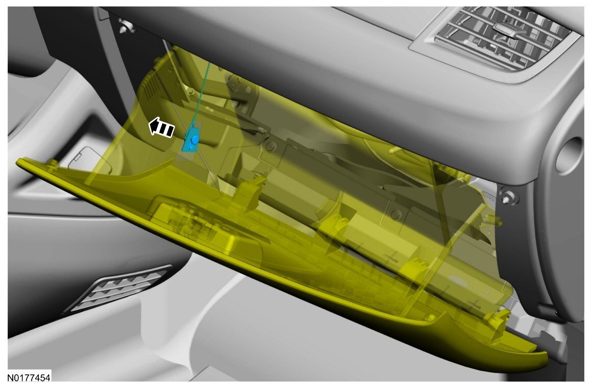
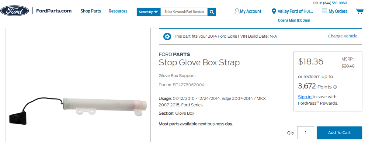
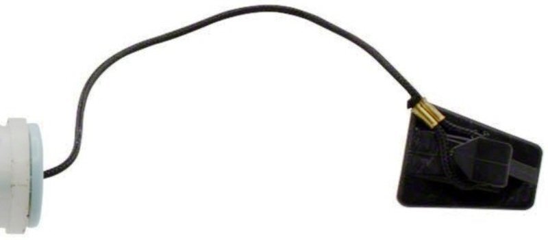
Welcome to the Forum @senciner! Link to this FordParts webpage The above-shown black plastic fitting -- which should be on the crimped metal cylinder shown in your photo on the frayed-end woven cord -- attaches to the glove compartment door to dampen its downward movement... Good luck!

-
If your 2020 Edge SEL is equipped with the factory Class II Trailer Tow Package, the following Special Service Message, issued effective October 7, 2021, may apply to the issue you describe... Good luck! SSM 50175 2015-2021 Edge, 2016-2018 MKX, 2019-2021 Nautilus - Parking Lamps Stay On And/Or Trailer Lights Flicker With Vehicle Turned Off Some 2015-2021 Edge, 2016-2018 MKX, and 2019-2021 Nautilus vehicles may exhibit the parking lamps stay on and/or the trailer lights flicker with vehicle turned off when a trailer is connected to the vehicle. This may be due to the software in the trailer module (TRM). To correct the condition, reprogram the TRM with the latest software of the appropriate Ford diagnostic scan tool. Use causal part 19H332 and applicable labor times from Section 10 of the Service Labor Time Standards (SLTS) Manual.