Haz
-
Posts
1,568 -
Joined
-
Last visited
-
Days Won
439
Content Type
Profiles
Forums
Gallery
Everything posted by Haz
-
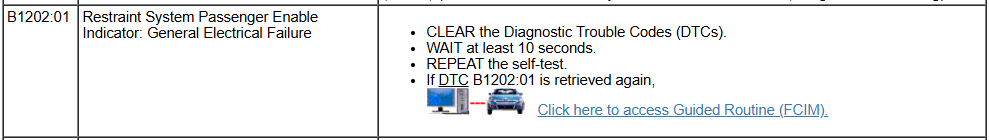
Help - Code: C1039:94-0A Active Front Steering (AFS) Lock
Haz replied to al303's topic in Brakes, Chassis & Suspension
@al303: Excerpts from 2018 Edge Workshop Manual, with emphasis added, and full sections attached below as PDF documents... Placing your device cursor over underlined acronyms may yield full-words descriptions of the acronyms. Adaptive Steering Overview The adaptive steering system provides steering assist to the driver by dynamically changing the steering ratio between the steering wheel and the road wheels, thereby reducing the number of steering wheel turns required to turn the road wheels. This is accomplished through the use of a motor, worm gear and toothed hub. All adaptive steering system components are inside the steering wheel, behind the driver air bag. Adaptive Steering System The SECM is self-monitoring and is capable of setting and storing Diagnostic Trouble Codes (DTCs). Depending on the nature of the DTC , the SECM may engage the adaptive steering lock and may send a request to the IPC to illuminate the adaptive steering system warning indicator and display a message in the message center alerting the driver of a potential adaptive steering system concern. The warning message is sent over the HS-CAN2 to the GWM where it is converted to a HS-CAN3 message and forwarded on to the IPC over the HS-CAN3 . Adaptive Steering Lock The adaptive steering system is designed with a locking device. While the lock is engaged, the steering system is set to a fixed (1:1) steering ratio. A sound may be heard when the vehicle is started or shut off as the lock is disengaged or engaged and a slight movement of the steering wheel may be noticed while the locking action is taking place. If the vehicle loses electrical power or the SECM detects a fault while driving, the lock is engaged. Extreme operating conditions may also cause the SECM to engage the lock. This strategy prevents overheating and permanent damage to the adaptive steering system. Typical steering and driving maneuvers allow the system to cool and return to normal operation. While the lock is engaged, it is possible the steering wheel may not be straight when the vehicle is driving straight ahead and the driver may notice the steering wheel angle or "clear vision" may be off-set. The locking solenoid also engages when the ignition is set to ON and the driver door is closed, this prevents the steering wheel from turning unnecessarily while the system is off and affecting steering wheel clear vision. The locking solenoid disengages once the engine is started. Adaptive Steering System - Diagnosis and Testing PINPOINT TEST K: STEERING LOCK CONCERN Introduction Normal Operation and Fault Conditions With the ignition ON, the SECM monitors various inputs to detect if a fault is present. DTC Fault Trigger Conditions DTC Description Fault Trigger Condition C1039:7F Active Front Steering (AFS) Lock: Actuator Stuck Off Sets when the SECM cannot activate the adaptive steering lock at engine start. C1039:92 Active Front Steering (AFS) Lock: Performance Or Incorrect Operation Sets when the SECM detects the adaptive steering lock fails the unlocking test. C1039:94 Active Front Steering (AFS) Lock: Unexpected Operation Sets when the SECM detects the adaptive steering lock fails the integrity test or the locking disc calibration test. C200D:28 Motor Rotation Angle Sensor: Signal Bias Level Out Of Range/Zero Adjustment Failure Sets when the SECM detects the adaptive steering motor angle sensor signal is outside the normal operating range or if the sensor is incapable of learning the center position. C200D:62 Motor Rotation Angle Sensor: Signal Compare Failure Sets when the SECM detects the adaptive steering motor angle sensor fails to learn the center position. U2001:92 Reduced System Function: Performance Or Incorrect Operation Sets due to a restraint airbag impact event or a fuel cutoff event. Due to the fault setting conditions, the installation of a new steering wheel and SECM are not covered under the vehicle warranty. Subsequently, a RVC is not provided for component replacement due to this DTC. U3000:46 Control Module: Calibration/Parameter Memory Failure Sets when the SECM detects an internal fault. U3000:49 Control Module: Internal Electronic Failure Sets when the SECM detects an internal fault. U3000:61 Control Module: Signal Calculation Failure This DTC sets due to an incomplete or an improperly performed trim routine. U3000:9A Control Module: Component or System Operating Conditions Sets when the SECM detects an internal fault. Possible Causes Incorrect sensor input SECM (steering wheel) K1 CARRY OUT THE SASM (STEERING ANGLE SENSOR MODULE) MODULE RESET ROUTINE NOTE: If present in any module, diagnose DTC U3003:16, U3003:1C or U3003:68 before diagnosing DTC C1039:7F, C1039:92 or U3000:49. Ignition ON. Using a diagnostic scan tool, carry out the SASM Module Reset routine. No VCM Recognized Ignition OFF. Start the engine and wait 20 seconds for the SECM to wake up and test the adaptive steering system. Ignition ON. No VCM Recognized Is the original DTC from the DTC Fault Trigger Conditions table retrieved again? Yes GO to K2. No For all other DTCs , REFER to the SECM DTC Chart. If no DTCs are present, the concern is not present and the system is operating correctly at this time. K2 CHECK FOR SASM (STEERING ANGLE SENSOR MODULE) DTCS No VCM Recognized Are any SASM DTCs present? Yes DIAGNOSE the DTCs present. REFER to Section 206-09 in the Workshop Manual. No GO to K3. K3 VERIFY ALL WIRING CONNECTIONS Ignition OFF. Disconnect all SECM electrical connectors. Using a good light source, inspect all disconnected electrical connectors for the following: corrosion - install new connector or terminal and clean the module pins damaged or bent pins - install new terminals or pins pushed-out pins - install new pins as necessary spread terminals - install new terminals as necessary Are the connectors free of corrosion, damaged pins, bent pins, pushed-out pins and spread terminals? Yes For all others: GO to K4. No REPAIR the connector or terminals. Refer to Wiring Diagrams Cell 5 for schematic and connector information. K4 CHECK FOR CORRECT SECM (STEERING EFFORT CONTROL MODULE) OPERATION Connect all SECM electrical connectors. Make sure they seat and latch correctly. Operate the system and determine if the concern is still present. Is the concern still present? Yes INSTALL a new Steering Wheel (SECM) assembly. CHECK OASIS for any applicable service articles: TSBs , GSB, SSM#2 or FSA. If a service article exists for this concern, DISCONTINUE this test and FOLLOW the service article instructions. If no service articles address this concern, INSTALL a new SECM (part of the steering wheel). REFER to Section 211-04 in the Workshop Manual. Generate RVC only works in single-step view No The system is operating correctly at this time. The concern may have been caused by a loose or corroded connector. ADDRESS the root cause of any connector or pin issues. K5 CHECK FOR CORRECT SECM (STEERING EFFORT CONTROL MODULE) OPERATION Connect all SECM electrical connectors. Make sure they seat and latch correctly. Operate the system and determine if the concern is still present. Is the concern still present? Yes INSTALL a new Steering Wheel (SECM) assembly. CHECK OASIS for any applicable service articles: TSBs , GSB, SSM#2 or FSA. If a service article exists for this concern, DISCONTINUE this test and FOLLOW the service article instructions. If no service articles address this concern, INSTALL a new SECM (part of the steering wheel). REFER to Section 211-04 in the Workshop Manual. No The system is operating correctly at this time. The concern may have been caused by a loose or corroded connector. ADDRESS the root cause of any connector or pin issues. If you're inclined toward fuller do-it-yourself efforts to resolve the issue, I can provide additional procedures and resources, otherwise this provides you a glimpse at what a professional technician at the dealership or an independent repair facility may be considering. Link to this FordParts webpage Good luck! Adaptive Steering - Overview - 2018 Edge Workshop Manual.pdf Adaptive Steering - System Operation and Component Description - 2018 Edge Workshop Manual.pdf PINPOINT TEST K - STEERING LOCK CONCERN - Diagnosis and Testing - 2018 Edge Workshop Manual.pdf Steering Wheel - Vehicles With Adaptive Steering - Removal and Installation - 2018 Edge Workshop Manual.pdf -
Weird acting rear light…
Haz replied to FLvet85's topic in Glass, Lenses, Lighting, Mirrors, Sunroof (BAMR), Wipers
The PDF documents attached below may be useful supplements to the information @Wubster100 has shared... Good luck! Rear Turn Signal-Stop-Hazard Lamps, Low Series - Wiring Diagram - 2016 Edge.pdf Rear Turn Signal-Stop-Hazard Lamps, High Series - Wiring Diagram - 2016 Edge.pdf BODY CONTROL MODULE (BCM) - Connector C2280D Pinout - 2016 Eddge.pdf BODY CONTROL MODULE (BCM) - Connector C2280D Location - 2016 Eddge.pdf BODY CONTROL MODULE (BCM) - Connector Locatio Illustration - 2016 Eddge.pdf REAR LAMP ASSEMBLY LH - Connector C412 Pinout - 2016 Edge.pdf REAR LAMP ASSEMBLY RH - Connector C415 Pinout - 2016 Edge.pdf -
Good luck! Parking Aid - 360 Degree View Camera Alignment - 2020 Nautilus Workshop Manual.pdf Parking Aid - 360 Degree Camera - 2020 Nautilus Owner's Manual.pdf Parking Aid - 180 Degree Camera - 2022 Edge Owner's Manual.pdf
-
@Wubster100: Relevant information from 2020 Nautilus and 2022-2024 Edge Owner's Manuals, Workshop Manuals, and Wiring Resources, is attached as PDF documents below and in an immediately following post, due to Forum file attachment limitations... Touchscreen WITH Front Split View Camera - APIM & IPMB Wiring Diagram - 2022-2024 Edge.pdf Rear View Camera - Touchscreen WITHOUT Front Split View Camera - Wiring Diagram - 2022-2024 Edge.pdf APIM Module Communications - Wiring Diagram #1 - 2022-2024 Edge.pdf APIM Module Communications - Wiring Diagram #2 - 2022-2024 Edge.pdf APIM & IPMB Grounds - Wiring Diagram - 2022-2024 Edge.pdf APIM Power Distribution - Wiring Diagram - 2022-2024 Edge.pdf SYNC MODULE (APIM) - Connector C2383A Pinout - 2022-2024 Edge.pdf SYNC MODULE (APIM) - Connector C2383F Pinout - 2022-2024 Edge.pdf IMAGE PROCESSING MODULE B (IPMB) - Connector C3676A Pinout - 2022-2024 Edge.pdf IMAGE PROCESSING MODULE B (IPMB) - Connector C3676B Pinout - 2022-2024 Edge.pdf IMAGE PROCESSING MODULE B (IPMB) Module Communications - Wiring Diagram - 2022-2024 Edge.pdf Rear View Camera - Touchscreen WITH Front Split View Camera - IPMB Wiring Diagram - 2022-2024 Edge.pdf Front Split View Camera - Power Distribution & IPMB Wiring Diagram - 2022-2024 Edge.pdf AUDIO CONTROL PANEL (Front Camera Switch) - Connector C2009 Pinout - 2022-2024 Edge.pdf AUDIO CONTROL PANEL (Front Camera Switch) - APIM & HVAC Wiring Diagram - 2022-2024 Edge.pdf HVAC MODULE - Connector C228B Pinout - 2022-2024 Edge.pdf Parking Aid - Overview - 2022-2024 Edge Workshop Manual.pdf Parking Aid - Component Location - 2022-2024 Edge Workshop Manual.pdf Parking Aid - System Operation and Component Description - 2022-2024 Edge Workshop Manual.pdf Parking Aid - 360 Degree View Camera Alignment - 2022-2024 Edge Workshop Manual.pdf Image Processing Module B (IPMB) - Removal and Installation - 2022-2024 Edge Workshop Manual.pdf 360 Camera - Wiring Diagram #1 - 2020 Nautilus.pdf 360 Camera - Wiring Diagram #2 - 2020 Nautilus.pdf 360 Camera - Wiring Diagram #3 - 2020 Nautilus.pdf 360 Camera - Wiring Diagram #4 - 2020 Nautilus.pdf IMAGE PROCESSING MODULE B (IPMB) - Connector C3676B Pinout - 2020 Nautilus.pdf IMAGE PROCESSING MODULE B (IPMB) - Connector C3676A Pinout - 2020 Nautilus.pdf EXTERIOR MIRROR LH - Connector C517 Pinout - 2020 Nautilus.pdf EXTERIOR MIRROR RH - Connector C615 Pinout - 2020 Nautilus.pdf Parking Aid - Component Location - 2020 Nautilus Workshop Manual.pdf Parking Aid - Overview - 2020 Nautilus Workshop Manual.pdf Parking Aid - System Operation and Component Description - 2020 Nautilus Workshop Manual.pdf Side Parking Aid Camera - Removal and Installation - 2020 Nautilus Workshop Manual.pdf
-
Labor hours to replace an oil pan.
Haz replied to rjburer's topic in Dealership & Vendor Experiences
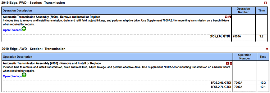
Oil Pan - Removal and Installation - 2.0L EcoBoost - 2019 Edge Workshop Manual.pdf Transmission - Removal and Installation - 2.0L EcoBoost - 2019 Edge Workshop Manual.pdf Good luck!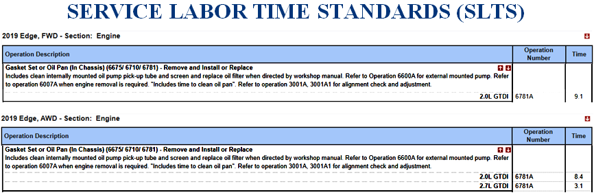
-
From the 2020 Edge Workshop Manual, with emphasis added... Spare Tire And Mismatched Tire Sizes Major dissimilar tire sizes between the front and rear axles could cause the AWD system to stop functioning and default to FWD or damage the AWD system. It is recommended to reinstall a repaired or replaced road tire as soon as possible. When a mismatched or tire of the wrong size is fitted, an AWD OFF message may appear in the IPC . If this condition occurs, a DTC is set and an AWD OFF message is displayed on the message center. If there is an AWD malfunction service required message in the message center from using a spare or mismatched tire, this indicator should turn off after reinstalling a tire of the same size as the normal road tire, then cycling the ignition OFF and ON. Good luck!
-
@TourGuide: The content of 2.7L EcoBoost PTU documents is identical to the above-posted 2.0L EcoBoost versions. I saw 2.0L Forum posts on your Profile and just assumed -- and we all know what that makes me! Good luck!
-
@TourGuide: Information on your Edge's PTU from the 2019 Edge Workshop Manual. attached below as PDF documents... Good luck! Power Transfer Unit (PTU) Draining and Filling - 2.0L EcoBoost - General Procedures - 2019 Edge Workshop Manual.pdf Power Transfer Unit (PTU) - 2.0L EcoBoost - Description and Operation - 2019 Edge Workshop Manual.pdf Power Transfer Unit (PTU) - 2.0L EcoBoost - Specifications - 2019 Edge Workshop Manual.pdf Power Transfer Unit (PTU) Fluid Level Check - 2.0L EcoBoost - General Procedures - 2019 Edge Workshop Manual.pdf

-
@STBEAST: PTU Description and Operation section for 2.7L EcoBoost, from the 2022-2024 Edge Workshop Manual, attached below as PDF document... Good luck! Power Transfer Unit - Description and Operation - 2.7L EcoBoost - 2022-2024 Edge Workshop Manual.pdf
-
Welcome to the Forum @mskotlarek1, and thank you for raising up your courageous daughter who is among the valiant Airmen who represent our country's strength around the world! We are indebted to your daughter, yourself, and the rest of your family for the sacrifices you all make on our behalf. A good first step toward resolving the throttle control issue on your daughter's Edge can be having the vehicle's electronic modules scanned for Diagnostic Trouble Codes (DTCs), which provide guidance toward subsequent diagnostic efforts to determine the throttle control issue's root cause. If you don't have a Code Reader device immediately available to you, consider calling around to Auto Parts stores nearby and ask about their capability (and any cost) of performing a DTC scan on the Edge, with them providing you a list of the any DTC(s) found. Please report any found DTC(s) back here, and we'll offer you fuller advice, which can include diagnostic and repair procedures -- if you are interested and equipped to attempt those next-steps yourself, as opposed to having a professional technician at a nearby dealership or an independent repair shop address the repair. It seems likely your daughter's Edge is a United States-market vehicle that she has repatriated following her buying it in Italy, but if the Edge was originally an EU-market vehicle, please let us know. Once again, thank you for your daughter's Service. Good luck!
-
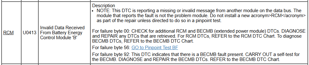
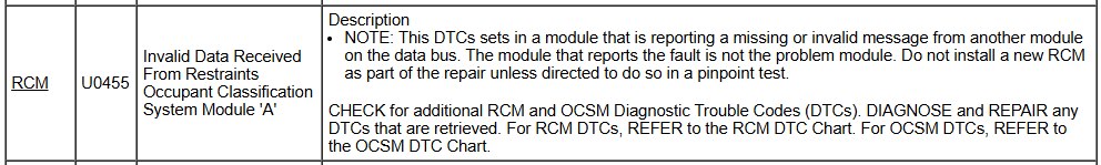
To emphasize the importance of your Health and Safety awareness, the SRS Depowering and SRS Repowering procedures are included here and are also provided below as PDF documents... From the Workshop Manual's Anti-Lock Brake System (ABS) and Stability Control section, with emphasis added... Stability Control Sensors The stability control sensors for the vehicle dynamic system consist of the yaw rate sensor, lateral accelerometer, longitudinal accelerometer and roll rate sensor. The sensors are housed in the RCM which sends sensor information to the ABS module over the HS-CAN2 . If any of the sensors are defective, a new RCM must be installed. The yaw rate sensor measures the yaw angle which is the difference between the direction the vehicle is pointing when cornering and the direction the vehicle is actually moving. The longitudinal accelerometer measures the acceleration and deceleration of the vehicle as it moves forward and backward. The lateral accelerometer measures the force created when a vehicle corners that tends to push a vehicle sideways. The roll rate sensor measures the rate of rotation of the vehicle along the centerline of the vehicle from front to back. Lateral acceleration has 2 forms. The first is the centrifugal acceleration that is generated when the vehicle travels around in a circle. The second is the acceleration due to gravity. On level ground there is no lateral acceleration due to gravity. However, if the vehicle is parked sideways on a bank or incline, the sensor measures some lateral acceleration due to gravity, even though the vehicle is not moving. A professional dealership technician may use Ford Diagnostic and Repair System (FDRS) diagnostic scan tool connected to Ford's servers to likely run a VIN-specific Guided Routine (RCM) of PINPOINT TEST AG: STABILITY CONTROL SENSOR EVENT INFORMATION FAULTS (C006X:68) to determine if replacement of the RCM is indicated by the step-by-step Pinpoint Test results. Work safely. Supplemental Restraint System (SRS) Depowering - General Procedures - 2018 Edge Workshop Manual.pdf Supplemental Restraint System (SRS) - Wiring Diagram 1 - 2018 Edge.pdf RESTRAINTS CONTROL MODULE (RCM) - Connector C310 Pinout - 2018 Edge.pdf RESTRAINTS CONTROL MODULE (RCM) - Connector C310 Location - 2018 Edge.pdf BATTERY ENERGY CONTROL MODULE B (BECMB) - Connector C2518 Pinout - 2018 Edge.pdf BATTERY ENERGY CONTROL MODULE B (BECMB) - Connector C2518 Location - 2018 Edge.pdf Supplemental Restraint System (SRS) - Wiring Diagram 2 - 2018 Edge.pdf OCCUPANT CLASSIFICATION SYSTEM MODULE (OCSM) - Connector C3043 Pinout - 2018 Edge.pdf OCCUPANT CLASSIFICATION SYSTEM MODULE (OCSM) - Connector C3043 Location - 2018 Edge.pdf OCCUPANT CLASSIFICATION SYSTEM MODULE (OCSM) - Removal and Installation - 2018 Edge Workshop Manual.pdf Supplemental Restraint System (SRS) Repowering - General Procedures - 2018 Edge Workshop Manual.pdf Gateway Module - Power Distribution Wiring Diagram - 2018 Edge.pdf
Depowering-GeneralProcedures-2018EdgeWorkshopManual.thumb.jpg.a88cf6661fc06b9cf96b7543efde2681.jpg)
Repowering-GeneralProcedures-2018EdgeWorkshopManual.thumb.jpg.b60bd7d8858304d84fd413e40d64e3be.jpg)
-
From the 2007 MKX Workshop Manual... Good luck! Anti-Theft NOTE: The smart junction box (SJB) is also known as the generic electronic module (GEM). The passive anti-theft system (PATS) consists of the following components: Anti-theft indicator (located in the instrument cluster [IC]) Encoded ignition integrated keyhead transmitter (IKT) PATS key(s) (the key contains a transponder and a remote keyless entry [RKE] transmitter) Encoded (the key contains a transponder) ignition PATS keys (not factory equipped, but may be used in place of IKT keys) PATS transceiver IC PCM PATS uses radio frequency identification technology to deter a drive-away theft. Passive means that it does not require any activity by the user. The vehicle is equipped with 2 IKT PATS keys. The IKTs operate as a standard PATS key with an RKE transmitter incorporated into the keyhead. The IKTs require batteries for the RKE transmitter to operate. A maximum of 4 IKT keys can be programmed to operate the vehicle. If more than 4 IKT keys are programmed, the RKE portion of the additional keys do not operate and the SJB and the IC set a memory full DTC (B1138 — Memory Full). These additional keys will start the vehicle, but will not operate the RKE system. If additional PATS keys are desired, a standard PATS key (a non-IKT key) can be used. For the purposes of this section, the PATS portion of the IKT key is referred to as a PATS key. PATS Function NOTE: If the IC or the PCM (or both) is replaced, the parameters must be re-set in both modules or the vehicle will experience a PATS no-start. Refer to Passive Anti-Theft System (PATS) Parameter Reset in this section. The PATS function is controlled by the IC. The PATS uses the IC to carry out all of the PATS functions such as receiving the identification code from the PATS key, issuing a signal to the PCM to control the starter and fuel injectors enable, and initiating the key interrogation sequence when the ignition key is turned to the ON or START position. Because of the interaction between the IC and the PCM, there are parameters that must be set if the IC or the PCM (or both) are replaced. Refer to Passive Anti-Theft System (PATS) Parameter Reset in this section. If the IC must be replaced for any reason (PATS concerns or an IC concern), the PATS keys also must be programmed into the new IC. Refer to Integrated Keyhead Transmitter (IKT) Key Programming Using Diagnostic Equipment in this section. All elements of PATS must be functional before the vehicle will start. If any of the components are not working correctly, the vehicle will not start. PATS is active only for a few seconds when the vehicle is starting. It is not a PATS concern if the vehicle stalls after it has been running for a minimum of 3 seconds. PATS will not disable a running vehicle. PATS may cause a vehicle no start due to either the fuel injectors or the starter not operating (starter relay does not close) or both. Always check for PATS DTCs from the IC and DTCs from the PCM when a no-crank or no-start condition exists. A low state of charge (SOC) in the vehicle battery may cause the PATS to allow starter operation, but prevent the fuel injectors from operating. If the theft light does not prove out (it may be either flashing or glowing steadily) and one (or both) of the previous conditions (fuel injectors and/or starter inoperative) are present, it may be due to a PATS issue. If the theft light proves out, it may not be a PATS issue. If the theft light does not illuminate at all, it may be an IC issue. GO to Symptom Chart. PATS is not compatible with aftermarket remote start systems, which allow the vehicle to be started from the exterior of the vehicle. These systems may reduce the security of the vehicle, and also may be the cause of no-start concerns. Remote start systems must be removed from the vehicle before any PATS-related no-start concerns are investigated.
-
Welcome to the Forum @99jhawk! Introductory diagnostic descriptions from the 2018 Edge Workshop Manual for most of your Edge's listed Diagnostic Trouble Codes (DTCs) are shown below... I was unable to immediately locate B005:01-28, U3000:4A-28, and U2300:64-28 without knowing the module(s) exhibiting the DTC(s). Regardless of those three DTCs, your intuition to leave the diagnostic & repair tasks to a professional dealership technician is valid, based upon the general caution Ford offers when dealing with Supplemental Restraint System (SRS) issues: WARNING: Incorrect repair techniques or actions can cause an accidental SRS deployment. Never compromise or depart from these instructions. Failure to precisely follow all instructions could result in serious personal injury from an accidental deployment. Good luck! Placing your device cursor over underlined acronyms may yield popup full-words descriptions of the acronyms. PINPOINT TEST L: OCS FAULTS REPORTED BY RCM Introduction Normal Operation and Fault Conditions The RCM is in constant communication with various control modules on the HS-CAN 2. One of those modules is the OCSM . The RCM continuously monitors the HS-CAN 2 for fault messages reported by the OCSM . The RCM also checks for the correct identification of the OCSM . If the RCM receives fault message(s) from the OCSM , it stores DTC B00A0:09, B00A0:4A, B00A0:63, B00A0:64 or B00A0:68 in memory and sends a message to the IPC to illuminate the airbag warning indicator. DTC Fault Trigger Conditions DTC Description Fault Trigger Condition B00A0:09 Occupant Classification System: Component Failure Sets when the RCM receives a message from the OCSM that a fault exists within the OCS. B00A0:4A Occupant Classification System: Incorrect Component Installed Sets when the RCM senses the OCSM is present but not configured. B00A0:63 Occupant Classification System: Circuit/Component Protection Time-Out Sets when the RCM receives 8 or more invalid states from the OCSM. B00A0:64 Occupant Classification System: Signal Plausibility Failure Sets when the RCM receives messages containing upper or lower data limits other than limits stored in memory. B00A0:68 Occupant Classification System: Event Information Sets when the RCM receives a message from the OCSM that indicates an OCS fault is present. Possible Causes OCSM DTCs OCSM RCM NOTE: Most faults are due to connector and/or wiring concerns. Carry out a thorough inspection and verification before proceeding with the pinpoint test. NOTE: Only disconnect or reconnect SRS components when instructed to do so within a pinpoint test step. Failure to follow this instruction may result in incorrect diagnosis of the SRS . PINPOINT TEST AG: STABILITY CONTROL SENSOR EVENT INFORMATION FAULTS (C006X:68) Introduction Normal Operation and Fault Conditions The RCM provides the stability/traction control system with acceleration sensor data over the HS-CAN 2. In addition to transmitting the data, the RCM monitors this data internally to make sure that the data is within an expected range. If the data is outside of the expected range and a fault is detected, the RCM stores DTC C0061:68, C0062:68, C0063:68, C0064:68, and/or C0065:68 in memory. However, the RCM does not request that the IPC illuminate the airbag warning indicator when these faults are present. DTC Fault Trigger Conditions DTC Description Fault Trigger Condition C0061:68 Lateral Acceleration Sensor: Event Information A fault is indicated when the lateral acceleration sensor is transmitting data that is outside of the range expected by the RCM. C0062:68 Longitudinal Acceleration Sensor: Event Information A fault is indicated when the longitudinal acceleration sensor is transmitting data that is outside of the range expected by the RCM. C0063:68 Yaw Rate Sensor: Event Information A fault is indicated when the yaw rate sensor is transmitting data that is outside of the range expected by the RCM. C0064:68 Roll Rate Sensor: Event Information A fault is indicated when the roll rate sensor is transmitting data that is outside of the range expected by the RCM. C0065:68 Vertical Acceleration Sensor: Event Information A fault is indicated when the vertical acceleration sensor is transmitting data that is outside of the range expected by the RCM. C006A:68 Multi-axis Acceleration Sensor: Event Information A fault is indicated when the multi-axis acceleration sensor is transmitting data that is outside of the range expected by the RCM. Possible Causes Aggressive driving conditions or rough roads RCM mounting RCM WARNING: Incorrect repair techniques or actions can cause an accidental SRS deployment. Never compromise or depart from these instructions. Failure to precisely follow all instructions could result in serious personal injury from an accidental deployment. NOTE: Most faults are due to connector and/or wiring concerns. Carry out a thorough inspection and verification before proceeding with the pinpoint test. NOTE: Only disconnect or reconnect SRS components when instructed to do so within a pinpoint test step. Failure to follow this instruction may result in incorrect diagnosis of the SRS . PINPOINT TEST AR: RCM IDENTIFIED AS CAUSE OF FAULT Introduction Normal Operation and Fault Conditions The RCM monitors various inputs and communicates on the CAN . If the values received are out of range or not what should be expected, the RCM sets a DTC . DTC Fault Trigger Conditions DTC Description Fault Trigger Condition B0080:11 Driver Seat Belt Load Limiter Deployment Control: Circuit Short To Ground Sets when the RCM detects an incorrect configuration. B0080:12 Driver Seat Belt Load Limiter Deployment Control: Circuit Short To Battery Sets when the RCM detects an incorrect configuration. B0080:13 Driver Seat Belt Load Limiter Deployment Control: Circuit Open Sets when the RCM detects an incorrect configuration. B0080:1A Driver Seat Belt Load Limiter Deployment Control: Circuit Resistance Below Threshold Sets when the RCM detects an incorrect configuration. B0080:2B Driver Seat Belt Load Limiter Deployment Control: Signal Cross Coupled Sets when the RCM detects an incorrect configuration. B1193:00 Crash Event Storage Full and Locked: No Sub Type Information Sets when the RCM has detected a crash event. B142D:00 Pyrotechnic End of Life Activation Performed: No Sub Type Information Sets when the RCM has experienced a pyrotechnic activation event. U2101:00 Control Module Configuration Incompatible: No Sub Type Information Sets when the RCM detects an incorrect configuration. U2200:00 Control Module Configuration Memory Corrupt: No Sub Type Information Sets when the RCM detects an incorrect configuration. U3000:04 Control Module: System Internal Failure Sets when the RCM detects an internal failure. U3000:46 Control Module: Calibration/Parameter Memory Failure Sets when the RCM detects an internal failure. U3000:49 Control Module: Internal Electronic Failure Sets when the RCM detects an internal failure. Possible Causes Intermittent concern RCM

-
GENERAL SERVICE BULLETIN Rear-View Mirror Concern Analysis 24-7133 16 December 2024 This bulletin supersedes 23-7173. Reason for update: add the interior review view mirror update Summary This article is designed to provide examples of interior and exterior rear-view mirror conditions/damage to assist in determining if the condition is warrantable or non-warrantable. Refer to the latest version of the Warranty and Policy Manual online for the latest rear-view mirror warranty coverage information. Use this article to assist in determining warrantable interior and exterior rear-view mirror concerns. Service Information Vehicles with power folding rear-view mirrors may exhibit concerns such as inoperative, folding with clicking sounds, vibrating/shaking in wind/while driving, or does not lock firmly in drive position. This may occur when the exterior rear-view mirrors are manually folded in such as going through a car wash, being bumped in transportation or a parking lot, or only one mirror is folded in. This may be attributed to the power folding mirror being out of synchronization or damage to the mirror mount. Perform the mirror synchronization procedure prior to completing any additional diagnostics. The synchronization procedure may need to be performed more than once to receive the loud popping sound, which is an indication the synchronization procedure has completed. Refer to WSM Section 501-09 Rear View Mirrors – General Procedures – Power Mirrors Synchronization. If the synchronization procedure does not correct the concern, continue with cleaning and inspection before performing additional diagnostics. Diagnostic test results and resynchronization information must be documented if a warrantable defect is found. Concerns that are corrected by the power mirror synchronization should not be submitted under warranty. Loose manual folding exterior rear-view mirrors are most commonly the result of damage to the assembly/mount. Closely inspect the exterior rear-view mirror after cleaning to review for witness marks/impact damage. Loose interior rear-view mirror mounts are most commonly the result of not being seated or the mount/attachment being damaged. Reseating the mirror per the WSM, Section 501-09 Rear View Mirrors may correct this concern. If the windshield has been replaced, damage to the mount can occur from improper removal/installation. Pen test A pen test should be used to determine mirror glass impact damage. Slowly run the tip of a ball point pen inside the crack throughout its entire length. If an impact is present, the pen helps to feel an impression. Cleaning procedure Clean the entire mirror assembly and glass to assist in verification of the customer concern and/or impact damage using water, a cloth, and car wash soap as needed. Do not clean any mirror glass or housing with an ice scraper, razor blade, abrasive pad, harsh chemicals or petroleum based cleaning products, as these may damage the mirror glass and/or housing. Use steel wool no greater than 0000 grade on the on the mirror glass only, in a circular motion then rinse/wipe with water or a non-abrasive glass cleaner. Examples Of Non-warrantable And Warrantable Conditions A rear-view mirror assembly can be damaged from abuse or impact and show little or no witness marks on housing. Shiny or flat spots on the housing indicate abuse or impact. Typical non-warrantable damage from abuse or impact Exterior mirror: • Mirror glass missing • Glass with scratches or cracks • Glass loose due to broken pivot or missing jackscrews • Scrapes on housing resulting from impact or abuse • Attachments loose due to impact • Broken mirror motor plate • Glass reattached (glued) after impact • Broken pivot neck/housing Interior mirror: • Interior mirror glass cracked • Broken windshield at mirror mount • Interior mirror detached pivot Typical warrantable conditions • Glass discoloration • Distorted mirror glass reflection • Electrical failure of motors and switches • Wiring harness shorted • Single line glass crack on heated mirror (verified with pen test) • Single line glass stress crack (verified with pen test) NOTE: All mirror components should be serviced at the lowest level available per the Warranty and Policy Manual. Over-repairs when lower-level components are available are subject to review and warranty adjustment. Dirty Mirror Housing (Non-warrantable) (Figure 1) Dirty mirror housings cannot be properly inspected for outside source influence. Mirrors returned without proper cleaning are subject to warranty review and adjustment. Figure 1 Scrapes, Impact, Broken Housing, Loose Attachment (Non-warrantable) (Figure 2) Figure 2 Power Folding Mirror Detent Pin Damage (Non-warrantable) (Figures 3-5) Power-fold trailer tow mirrors are designed to operate the mirror between home to folded position. They are also designed to manually fold forward beyond home position. If the mirror is forcefully pushed beyond the forward fold position, the detent pin in the mirror is damaged and will not stop at home position using the power-fold button. To test this, push the power-fold button. If the mirror unfolds forward past home position (using the power fold button), it is not warrantable. Figure 3 Figure 4 Figure 5 Grain Removed From Plastic Mirror Housing (Non-warrantable) (Figure 6) Physical damage that is often accompanied by power-fold mirror detent pin damage. Figure 6 Glass Loose, Broken Motor (Non-warrantable) (Figures 7-8) Figure 7 Missing mirror glass/backing plate missing (non-warrantable) (Figure 😎 Figure 8 Melted Housing (Non-warrantable) (Figures 9-10) Indicates exposure to excessive heat or chemical contact. Figure 9 Figure 10 Discolored Housing (Non-warrantable) (Figure 11) Stains may have a liquid drip or spray pattern (shown) from contact with harsh liquids. Figure 11 Discolored Glass (Warrantable) (Figure 12) Figure 12 Distorted Mirror Glass Reflection (Warrantable) (Figure 13) Figure 13 Single Line Crack On Heated Mirror (Warrantable) (Figure 14) This crack will occur from thermal stress. Refer to the pen test at the beginning of this article to determine impact damage. Figure 14 Distorted Puddle Lamp Projected Image (Warrantable) (Figure 15) Figure 15 Portion Of Missing Glass (Warrantable) (Figure 16) Adhesive is still present on the mirror backing plate which is securely attached to the motor. Figure 16 Interior Mirror Glass Cracked (Non-warrantable) (Figure 17) Excessive force including improper removal/installation. Figure 17 Broken Windshield (Non-warrantable) (Figure 18) Excessive force including improper removal/installation. Figure 18 Interior Mirror Detached Pivot (Non-warrantable) (Figure 19) Excessive force will detach the press fit pivots. Figure 19 Blocked Light Sensor (Non-warrantable) (Figure 20) Obstruction will cause inoperative automatic high beam. Figure 20 Smudge Interior Mirror (Figure 21) Use steel wool no greater than 0000 grade on the on the mirror glass only, in a circular motion then rinse/wipe with water or a non-abrasive glass cleaner. Figure 21 © 2024 Ford Motor Company All rights reserved. NOTE: This information is not intended to replace or supersede any warranty, parts and service policy, workshop manual (WSM) procedures or technical training or wiring diagram information.
- 1 reply
-
- 3
-

-
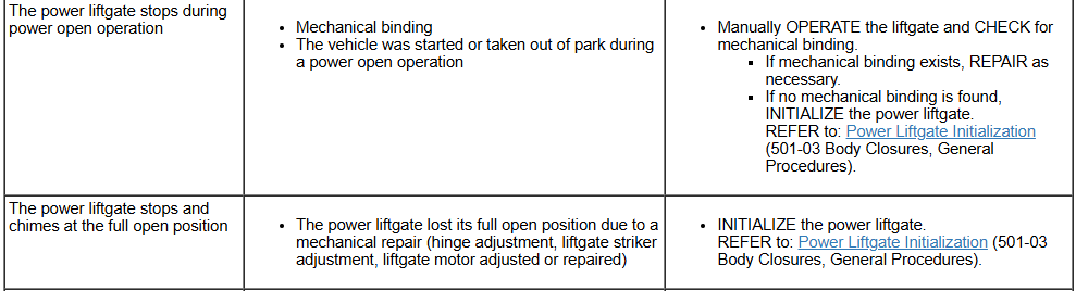
It's performing a scan of a single module -- or all modules -- for DTCs. Looking to the Workshop Manual's Power Liftgate diagnostic symptom chart... From Power Liftgate System Operation and Component Description... Power Open The power liftgate power open operation begins when: the RGTM detects the front power liftgate switch is activated. the RGTM detects the rear exterior liftgate release switch is activated. the RGTM receives a message from the BCM (indicating a request from a programmed RKE transmitter or a passive entry feature request). Once the RGTM receives an open request, the power liftgate opens by carrying out the following: The RGTM checks the gear selector lever position and vehicle speed status from the messages received. The RGTM supplies power to the unlatch motor, releasing the liftgate latch The RGTM monitors the liftgate ajar state (the liftgate latch pawl switch opens and both forkbolt switches close to indicate the latch has fully released). When the RGTM detects the power liftgate latch is fully unlatched, it supplies power to the drive motor, opening the power liftgate. While the power liftgate is opening, the RGTM monitors the liftgate motor position sensor for liftgate position and velocity. If an obstruction is detected, the RGTM stops the liftgate drive motor. When the power liftgate reaches the full open position, the RGTM removes the power from the drive motor. If any of the power liftgate switches is activated, a request for the hands-free feature is detected or a double press of the button on a RKE transmitter occurs during a power open, the liftgate stops and holds its position. Power Close The power liftgate power close operation begins when: the RGTM detects the front power liftgate switch is pressed. the RGTM detects the rear interior power liftgate switch is pressed. the RGTM receives a message from the BCM (indicating a double button press from a RKE transmitter or a hands-free request). Once the close request is received, the power liftgate closes by carrying out the following: The RGTM checks the gear selector lever position and vehicle speed status from the messages received. The RGTM starts an audible chime via the audio system. The RGTM supplies power to the drive motor. While the power liftgate is closing, the RGTM monitors the power liftgate motor position sensor (for liftgate position and velocity) and the anti-pinch switches. If an obstruction is detected, the power liftgate stops and reverses. The RGTM monitors the liftgate ajar state. When the RGTM detects the latch has engaged the striker (switches in the latch changing state), power is supplied to the cinching motor to pull the liftgate into the primary latch position and power is removed from the liftgate drive motor. When the RGTM detects the primary latch position has been reached (liftgate is fully closed), the RGTM reverses the direction of the cinching motor until the sector gear switch indicates a start position. If any of the power liftgate switches is activated, a request for the hands-free feature is detected or the button on the RKE transmitter is double pressed during a power close, the liftgate stops and holds its position. NOTE: The power liftgate may not operate correctly under the following conditions: Excessive weight (such as snow or ice) is present on the liftgate. A low voltage or drained battery. A disconnected battery. Repairs/adjustments have been made to the power liftgate strut, the power liftgate motor, the liftgate striker or the liftgate hinges. If any of these conditions have occurred, the power liftgate must be re-initialized. Refer to: Power Liftgate Initialization (501-03 Body Closures, General Procedures). Power Liftgate Open Height Programming The power liftgate open height can be programmed to open to a height other than the full open position. To program the power liftgate open height: Open the liftgate. Manually move the liftgate to the desired height. Press and hold the rear power liftgate close switch until a chime is heard, indicating that the new power liftgate maximum open height is successfully programmed. The programmed power liftgate height is retained when the battery is disconnected. Link to this FordParts webpage Good luck!

-
How about... Power Liftgate Initialization Initialization Disconnect the battery or remove the RGTM fuse(s). NOTE: Remove the battery power from the RGTM for 20 seconds before entering initialization mode. Wait 20 seconds and reconnect the battery or reinstall the RGTM fuse(s). If the liftgate is not already in the fully closed position, manually close and fully latch the power liftgate. Using a diagnostic scan tool, clear all fault codes for the RGTM . NOTE: If equipped, make sure the power liftgate system is turned ON in the message center before performing this step. NOTE: If the power liftgate does not open during this step, refer to the Symptom Chart to diagnose the inoperative power liftgate. Power open the liftgate by using a programmed RKE transmitter or the front control switch. Once the liftgate is fully open, power close the liftgate by using a programmed RKE transmitter or the front power liftgate control switch. Carry out the RGTM self-test. This Workshop Manual procedure and fuse-related references are attached below as PDF documents... Good luck! Power Liftgate Initialization - General Procedures - 2017 Edge Workshop Manual.pdf Rear Gate Trunk Module (RGTM) - Power Distribution-Fuses - 2017 Edge.pdf Battery Junction Box (BJB) - Bottom View Illustration - 2017 Edge.pdf Body Control Module (BCM) Illustration - 2017 Edge.pdf
-
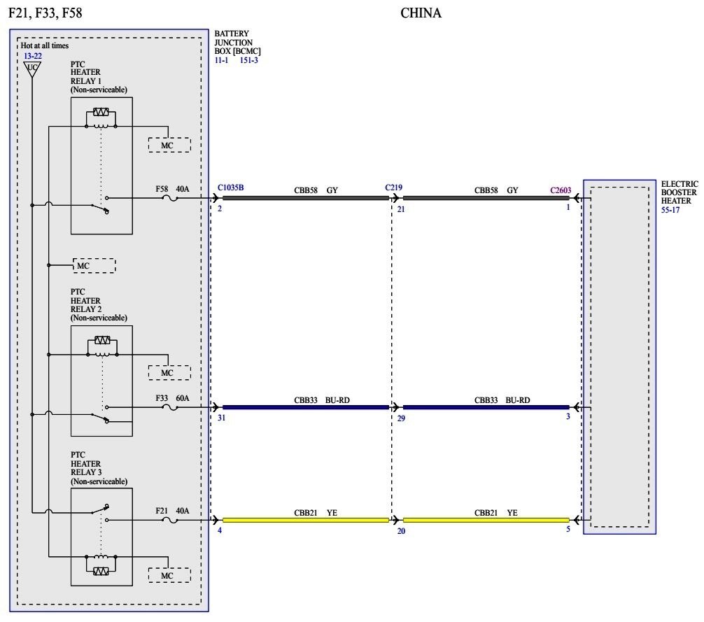
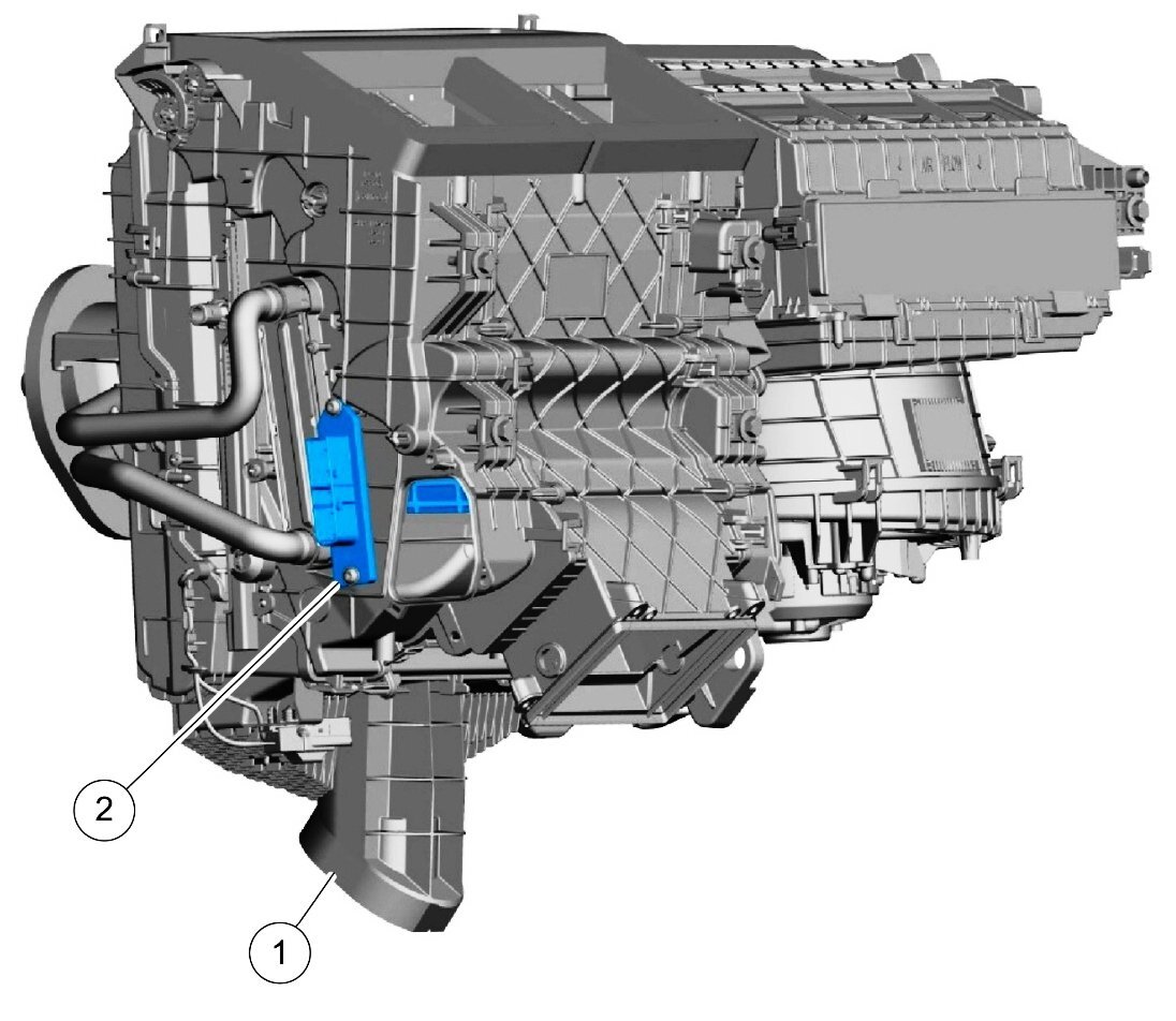
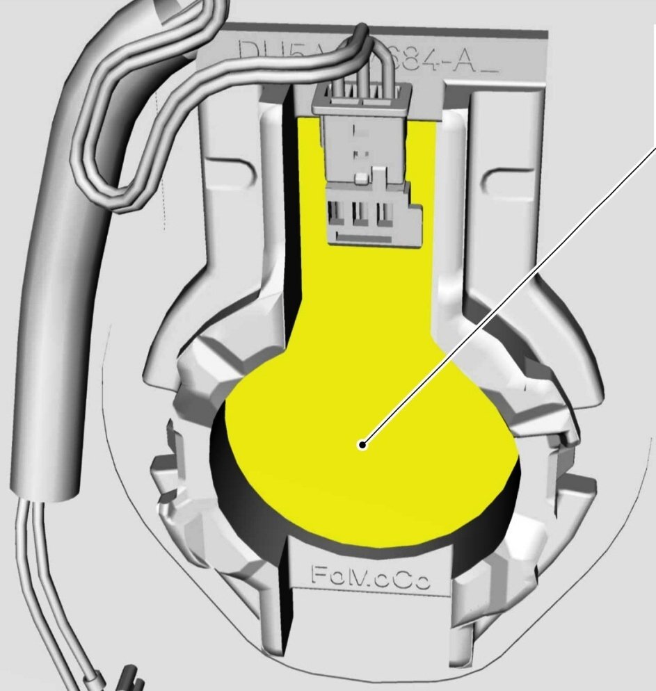
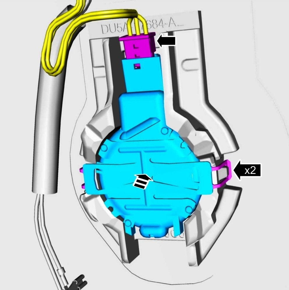
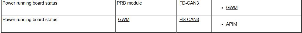
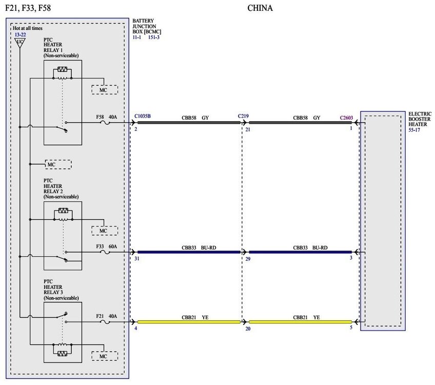
Welcome to the Forum @SummerBreeze! The 2024/2025 Nautilus wiring resources for the North American, Asia Pacific, and European market regions all depict a Power Running Board (PRB) module and circuits supporting power deployed/retracted running boards -- however -- there is absolutely no depiction of any related components or procedures associated with power running boards in the various regional Workshop Manuals, beyond this Module communication description... Additionally, there is also no mention of power running boards among official accessories listed for 2024/2025 Nautilus. Power Running Board-related wiring diagrams, along with connector details and locations, are attached below as PDF documents. The Battery Junction Box's (BJB) F21/F33/F58 fuse positions are associated with relayed circuits for the China-market Nautilus' Electric Booster Heater... Ford's online parts-selling site only shows a cover which closes the Climate Control Housing opening into which the Electric Booster Heater (element) is inserted for China-market Nautilus... Related wiring diagram and Workshop Manual procedure are attached below as PDF documents... Good luck! Power Running Board (PRB) Module & Motors - Wiring Diagram - 2024 Nautilus.pdf Power Running Board (PRB) Module - Connector C3313B - Pin-Circuit Details - 2024 Nautilus.pdf Power Running Board (PRB) Module - Connector C3313A - Pin-Circuit Details - 2024 Nautilus.pdf Power Running Board (PRB) Module - Connectors C3313A & C3313B - Location - 2024 Nautilus.pdf Power Running Board (PRB) Motor, LH - Connector C3185 - Pin-Circuit Details - 2024 Nautilus.pdf Power Running Board (PRB) Motor, LH - Connector C3185 - Location - 2024 Nautilus.pdf Power Running Board (PRB) Motor, RH - Connector C3186 - Pin-Circuit Details - 2024 Nautilus.pdf Power Running Board (PRB) Motor, RH - Connector C3186 - Location - 2024 Nautilus.pdf Power Running Board (PRB) Module - Power Distribution - Wiring Diagram - 2024 Nautilus.pdf Electric Booster Heater - CHINA - Power Distribution Wiring Diagram - 2025 Nautilus.pdf Electric Booster Heater - CHINA - Removal and Installation - 2025 Nautilus Workshop Manual.pdf


-
Windshield Replacement
Haz replied to 1004ron's topic in Glass, Lenses, Lighting, Mirrors, Sunroof (BAMR), Wipers
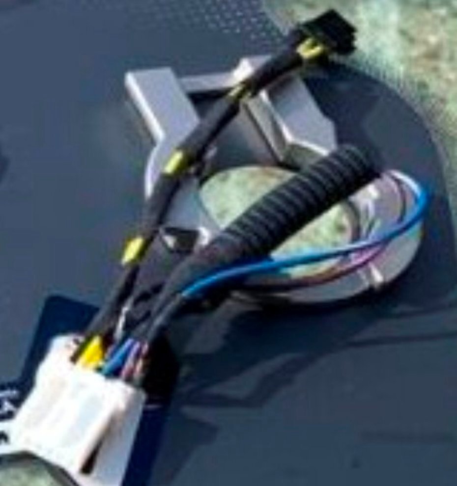
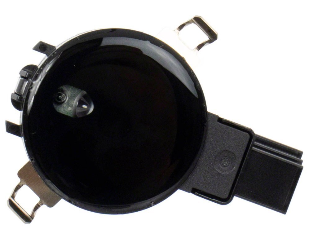
Ford's online parts-selling site offers a zoomable-scrollable exploded view illustration that denotes (with a gold-square icon) the Rain Sensor Mount being provided in assembly (PIA) to the Windshield... Link to this FordParts webpage In your photo of the replacement windshield... ...the configuration and depth of the Rain Sensor Mount locator cavity appears consistent with this illustration from the 2017 Edge Workshop Manual... FordParts' photo of the Rain Sensor Module shows two integral spring clips... ...which this Workshop Manual illustration shows snapping over two ears or lugs that are cast into the sides of the Rain Sensor Mount... Good luck!


-
@GTEyes: From the 2022-2024 Edge Workshop Manual, with emphasis added... Placing your device cursor over underlined acronyms may yield a popup full-words description of the acronyms. Climate Controlled Seat Operation The driver and passenger climate controlled seat buttons are selected from the touchscreen. The climate controlled seat system functions independently from the vehicle's climate control system. The seat cushion and backrest are each equipped with a blower motor assembly. As cabin air is drawn through each blower motor, a Thermo-Electric Device (TED) heats or cools the air, which is then directed into the foam pad where it is distributed along the surface of the cushion and backrest of the seat. Once the system is activated, the SCME uses a set of flexible algorithms to control the heating/cooling modes and the blower speed dependent on the commanded climate controlled seat settings. The SCME monitors seat cushion temperature while it supplies voltage and ground to both blower motors. The SCME also supplies a variable voltage signal to control the blower speed. Cabin air enters the blower through an integrated filter attached to the blower motor housing. Heated or cooled air exits the blower motor and flows through the foam pad. Climate Controlled Seat Heating Characteristics The system control settings are indicated next to each climate controlled seat heat switch button. The first setting is HIGH (3 indicators), the second setting is MED (2 indicators) and the third is LOW (1 indicator) then OFF (no indicators). When heating, the SCME varies the speed of the blower motors and the duty cycle of the integral Thermo-Electric Device (TED) in order to reach and maintain the desired temperature determined by the system control settings. Climate Controlled Seat Cooling Characteristics The system control settings are based on the 3 indicators next to each climate controlled seat cool switch button. The first setting is HIGH (3 indicators), the second setting is MED (2 indicators) and the third is LOW (1 indicator) then OFF (no indicators). When cooling, the SCME maintains a constant blower motor speed and a constant Thermo-Electric Device (TED) supply voltage (duty cycle is determined by the switch setting) in COOL mode. Climate Controlled Seat Recovery Mode NOTE: The presence of overtemperature faults (Diagnostic Trouble Codes (DTCs) B1153:4B, B1154:4B, B1151:4B and B1152:4B) can be induced by incorrectly operating the climate controlled seat system after an initial heat setting has been attained. If a heat setting is repeatedly turned off and on in an attempt to increase the seat temperature or repeatedly toggled between heat and cool modes, an overtemperature condition can result and the Diagnostic Trouble Codes (DTCs) may be set. If the temperature of one of the blower motors rises above 110° C (229.8° F) in the heat mode or 65° C (149° F) in the cool mode for more than 4 seconds, the SCME records an overtemperature DTC , removes voltage from the Thermo-Electric Devices (TEDs) (part of the blower motor assembly) and goes into recovery mode (blower only) for 30 seconds to cool down the blower motor. The same occurs if a temperature difference of 60° C (140° F) or greater is detected between the backrest and cushion blower motors on either front seat. The SCME continues to monitor the blower motors while in recovery mode. If the temperature of the Thermo-Electric Devices (TEDs) do not drop to 105° C (220.8° F) in the heat mode or 60° C (140° F) in the cool mode after 30 seconds, the system continues to cool the blower motors in recovery mode for up to 5 minutes. If the Thermo-Electric Devices (TEDs) cool down after 30 seconds, but before 5 minutes (checked at 4 second intervals), the system is operating normally. An overtemperature DTC is still recorded even if the system recovers and is operating normally. This is more likely to occur during extreme cabin temperatures with significant seat back sun load. If the system does not recover within 30 seconds in heat mode or within 5 minutes in cool mode, the SCME disables that seat (fault mode) and remains off until the ignition is cycled. Also, if the SCME detects a temperature differential fault twice during the same ignition cycle, the SCME disables the seat. When a fault causes a shutdown, the climate controlled seat indicators turn off and that seat is not operational until the next ignition cycle. Good luck!
-
Welcome to the Forum @Ferris In Michigan! A collection of 2010 Edge Workshop Manual sections that address Climate Control actuators are attached below as PDF documents... Good luck! Mode Door Actuator - Defrost-Panel-Floor Door - Removal and Installation - 2010 Edge Workshop Manual.pdf Mode Door Actuator - Air Inlet Door - Removal and Installation - 2010 Edge Workshop Manual.pdf Air Distribution and Filtering - Description and Operation - 2010 Edge Workshop Manual.pdf Control Components - Description and Operation - 2010 Edge Workshop Manual.pdf Temperature Blend Door Actuator - LH - Removal and Installation - 2010 Edge Workshop Manual.pdf Temperature Blend Door Actuator - RH, Dual-Zone EATC - Removal and Installation - 2010 Edge Workshop Manual.pdf
-
I would not consider using the seat in the way you describe without having the side air bag professionally removed... If your local Ford dealer refuses the job, you might try contacting an automotive upholstery shop. Good luck!
-
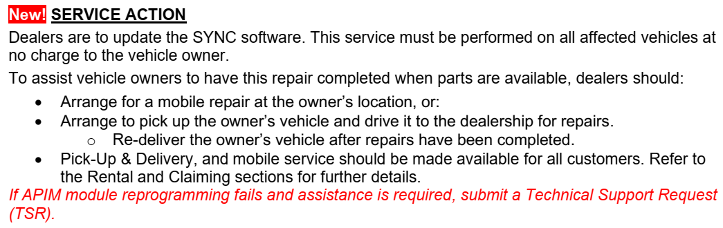
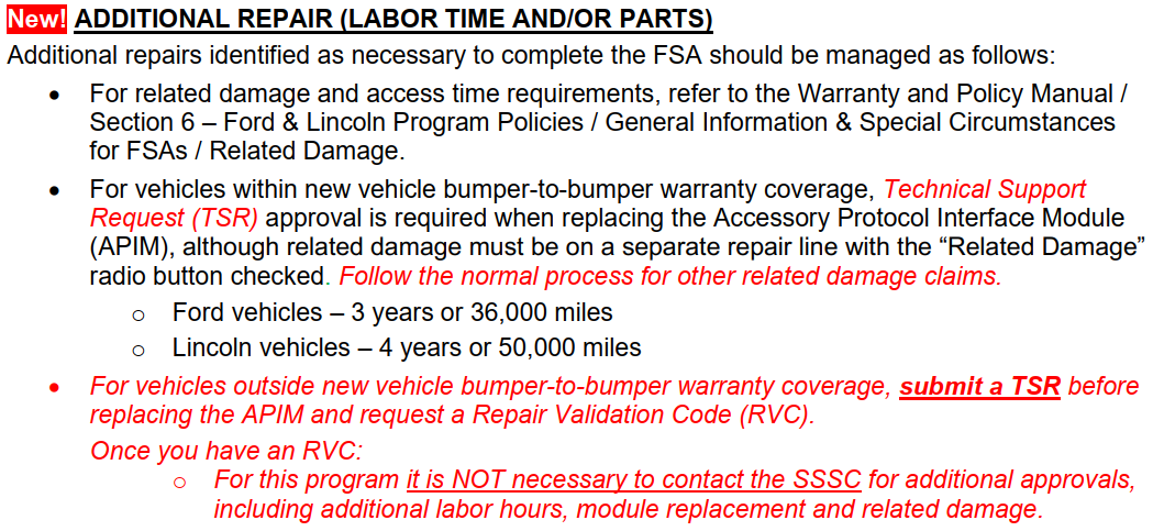
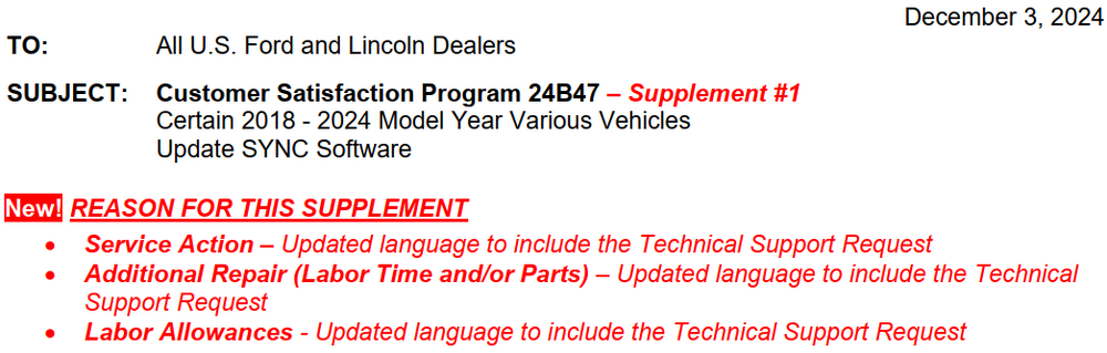
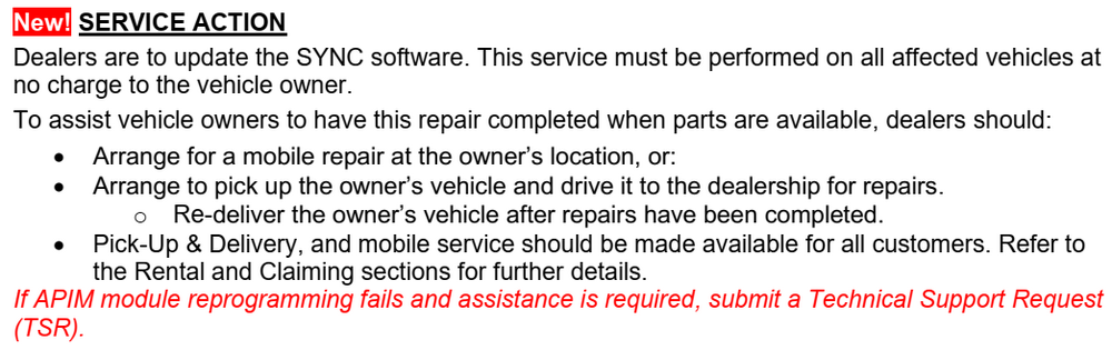
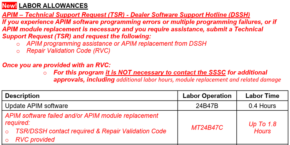
Ford has issued Supplement #1 to the Dealer Bulletin for Customer Satisfaction Program 24B47, reinforcing utilization of Technical Support (TSR) process and the Dealer Software Support (DSSH) Hotline when difficulties occur while performing the APIM software update, and/or if an APIM replacement is required to fulfill this Program, and providing additional Labor authorization for these TSR and DSSH interactions...

-
Ford has issued CSB 24B54 Supplement #1 to Dealers, with a revised date for Owner Letter mailing... ...increases the allowable Labor Time to conduct the Service Procedure... ...and revises the Service Procedure to improve the programming success rate. The updated Service Procedure with revised instructions shown in red text, formulated for dealership professional technicians using the Ford Diagnosis and Repair System (FDRS) to perform the software updates, is attached below as a PDF document... Owners who opt to perform the software updates on their own, will use the Over The Air (OTA) automatic download and installation method. In Canada, the only Supplement #1 difference is Canadian Owner Letters are expected to be mailed by mid-December 2024. CSP 24B54 Supplement #1 - Revised Service Procedure.pdf
-
Do 2011 tail lights fit a 2010
Haz replied to Hodgie's topic in Glass, Lenses, Lighting, Mirrors, Sunroof (BAMR), Wipers
@MDrumm03: The 2010 Workshop Manual indicates enabling/disabling hyperflash is programmable in the Smart Junction Box, via As-Built data in Line 726, with emphasis added... Module Configuration and Parameter Chart Module Module Address Requires PMI Reprogram/ Flash Capable Requires Adaptive Learning or Calibration Available Programmable Parameters Smart Junction Box (SJB) 726 Yes Yes Tire Pressure Monitoring System (TPMS) sensor training Autolock Auto-unlock Daytime Running Lamps (DRL) Global open Perimeter lighting mode Stop lamp outage enable/disable Tire placard pressure Hopefully, Forscan will allow the change via its menu of modifications, rather than you having to manually edit your Edge's Line 726 As-Built values to disable hyperflash. Good luck! Module Configuration - Diagnosis and Testing - 2010 Edge Workshop Manual.pdf


Depowering-GeneralProcedures-2018EdgeWorkshopManual.jpg.d1b088ec24b713439faa49f4ac742623.jpg)
Repowering-GeneralProcedures-2018EdgeWorkshopManual.jpg.f6f24d3797cf8b72aaba62dbcceb185c.jpg)