Haz
-
Posts
1,568 -
Joined
-
Last visited
-
Days Won
439
Content Type
Profiles
Forums
Gallery
Everything posted by Haz
-
Attached below as PDF documents, from the 2016 Edge Workshop Manual, providing an overview of removal and installation of the front & rear Door Glass Top Runs... Good luck! Front Door Glass Top Run - Removal and Installation - 2016 Edge Workshop Manual.pdf Rear Door Glass Top Run - Removal and Installation - 2016 Edge Workshop Manual.pdf
-
Special Service Message 53057 - 2024 Nautilus - Front Driver Door Can Not Be Unlocked Using Intelligent Access - Built On Or Before Jan 23, 2024 Some 2024 Nautilus vehicles built on or before Jan 23, 2024 may exhibit a condition where the front driver door can not be unlocked using the passive entry (Intelligent Access) feature. This may be due to the software in the body control module (BCM). To correct the condition, reprogram the BCM module using the latest software level of the Ford Diagnosis and Repair System (FDRS). For claiming, use causal part 15604 and applicable labor operations in Section 10 of the Service Labor Time Standards (SLTS) Manual.
-
2019 Ford Escape 1.5L bank 1 sensor 2 oxygen sensor
Haz replied to kevin kogut's topic in 2019-Current Edge & Nautilius
@kevin kogut: As before, attached below as PDF documents are relevant sections from the 2019 Escape Workshop Manual... Please be aware that some numbered action-step descriptions may appear at the bottom of the page before the illustration to which it applies. 1.5L EcoBoost Engine Item Description 1 Turbocharger bypass valve solenoid 2 CMP sensor RH exhaust 3 ECT sensor 4 HO2S 5 Catalyst monitor sensor 6 CHT 2 (CHT2) sensor 7 CKP sensor 8 Wastegate actuator 9 VCT oil control solenoid exhaust Good luck! Catalyst Monitor (Oxygen) Sensor - 1.5L EcoBoost - Removal and Installation - 2019 Escape Workshop Manual.pdf Air Cleaner Outlet Pipe - 1.5L EcoBoost - Removal and Installation - 2019 Escape Workshop Manual.pdf Battery Tray - 1.5L EcoBoost - Removal and Installation - 2019 Escape Workshop Manual.pdf Exhaust Gas Oxygen Sensor Socket - Rotunda Part Number 303-476.pdfSensor-1.5LEcoBoost-Item5InIllustration-2019EscapeWorkshopManual.jpg.00664fa8d09330f2b062f64572592147.jpg)
- 7 replies
-
- 1
-

-
- ford escape
- escape not edge
- (and 1 more)
-
2019 Ford Escape 1.5L bank 1 sensor 2 oxygen sensor
Haz replied to kevin kogut's topic in 2019-Current Edge & Nautilius
Welcome to the Forum, @kevin kogut! Presumably, your Edge is a 2.0L EcoBoost rather that a 1.5L. Attached below as PDF documents are the Workshop Manual procedure and info on the recommended special tool... Good luck! Catalyst Monitor (Oxygen) Sensor - Removal and Installation - 2019 Edge Workshop Manual.pdf Exhaust Gas Oxygen Sensor Socket - Rotunda Part Number 303-476.pdf- 7 replies
-
- 2
-
-
- ford escape
- escape not edge
- (and 1 more)
-
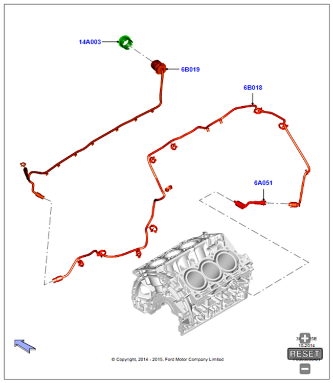
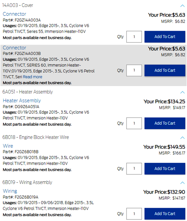
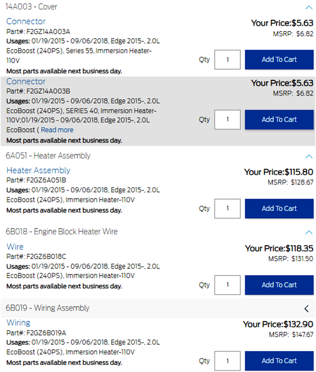
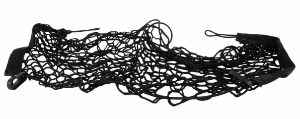
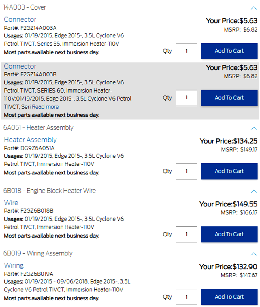
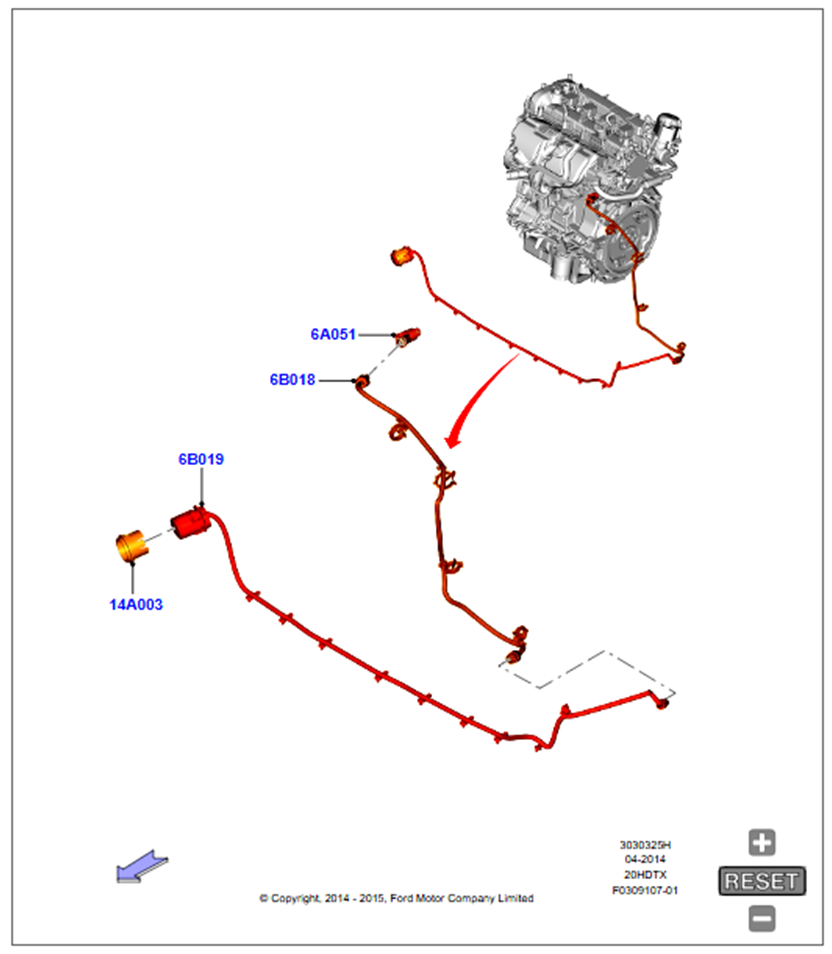
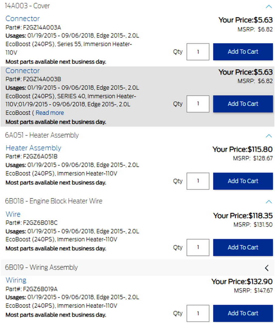
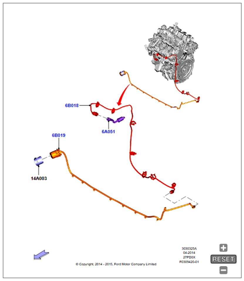
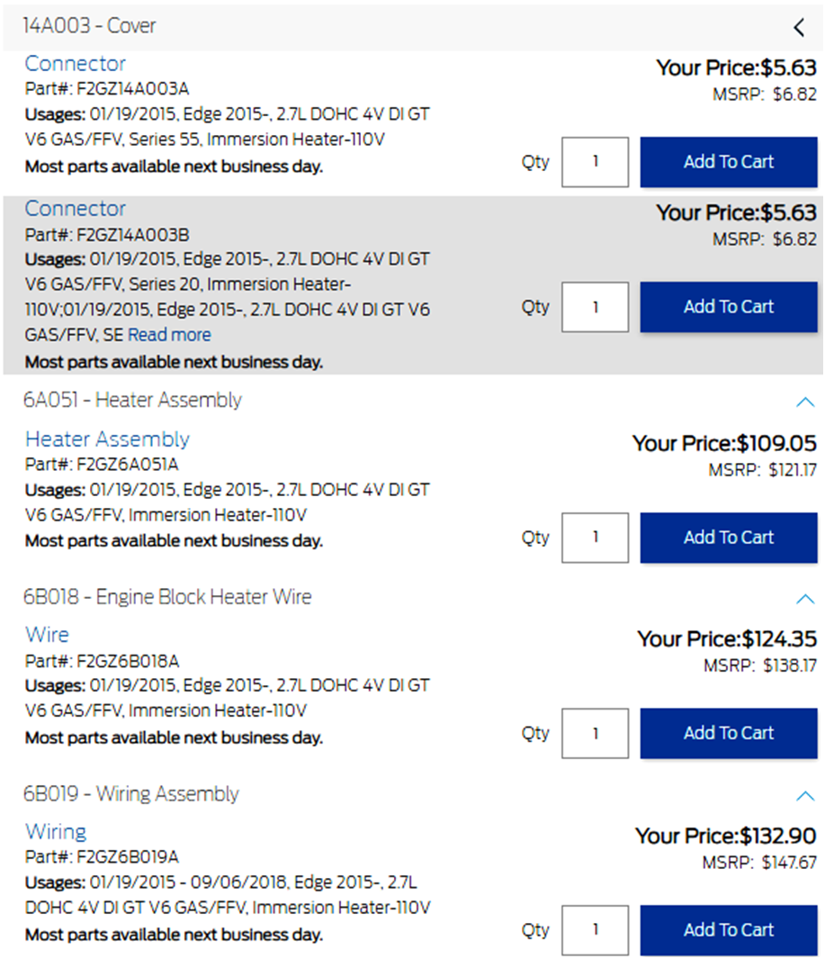
I cannot find any external lead-cord for factory-installed Edge block heaters depicted on Ford's online parts-selling site, FordParts. However, for anyone considering adding an engine block heater, here are parts numbers for various Edge engines... 3.5L & 3.7L TiVCT Duratec/Cyclone Engine 2.0L EcoBoost Engine 2.7L EcoBoost Engine Good luck!


-
2022 Edge ST rear fog light
Haz replied to WilkiST's topic in Glass, Lenses, Lighting, Mirrors, Sunroof (BAMR), Wipers
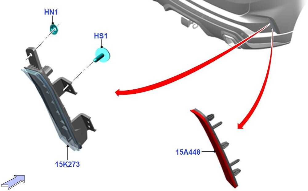
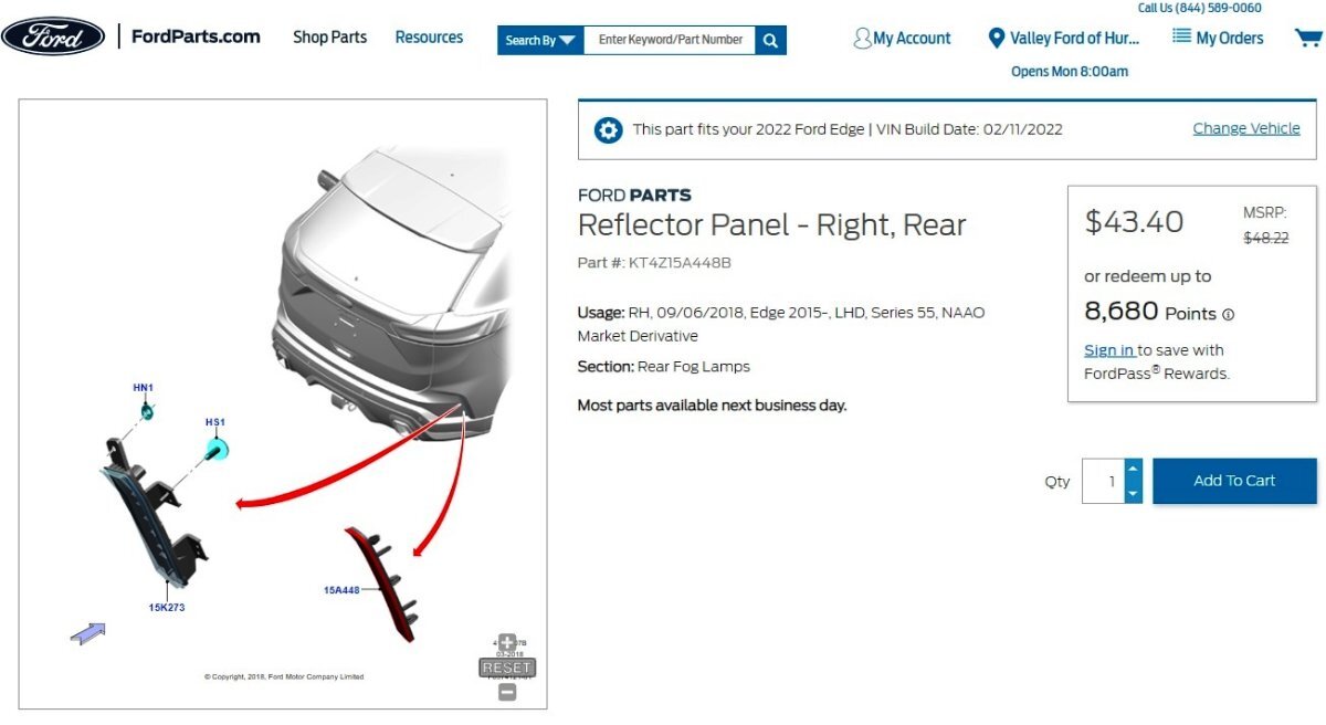
AP is the Regional Identifier for the Asia Pacific market. Using your Edge's North American market VIN to determine if any Trim Level differences in the installed Rear Bumper reflector assemblies, none are found -- meaning NA 2022 Edge SE/SEL/Titanium/ST-Line/ST all use the same Reflector Assembly... Link to web browser-zoomable/scrollable illustration shown in this FordParts Right Hand part listing The reflector-lens installed on North American Edges appears to use the same mount base as is provided for the Euro-Spec Rear Fog Lamp assemblies... ...with the North American reflector lens lacking the red semi-transparent lens portion of the Euro-Spec Rear Fog Lamp assemblies... Attached below as PDF documents are the Pin-Circuit descriptions for the North American & Euro-Spec versions of Headlamp Switch Connector C205, toward utilizing your installed Euro-spec headlamp switch's rear fog lamps button... Good luck! Headlamp Switch - Connector C205 Location - NA 2020 Edge.pdf Headlamp Switch - Connector C205 Pin-Circuit Details - NA 2020 Edge.pdf Headlamp Switch - Connector C205 Pin-Circuit Details - UK 2020 Edge.pdf
-KT4Z15A448B-FordParts_com.thumb.jpg.1618738084782a820351142c6a1b53a8.jpg)
-
2022 Edge ST rear fog light
Haz replied to WilkiST's topic in Glass, Lenses, Lighting, Mirrors, Sunroof (BAMR), Wipers
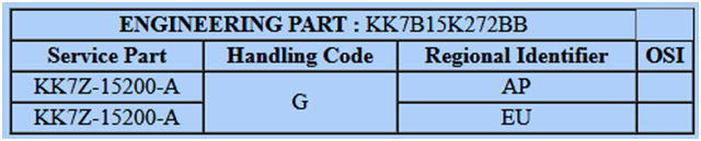
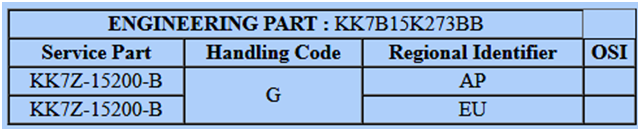
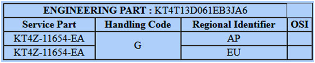
Searching UK used-vehicles-for-sale websites yields Euro-export ST-Line Edges with rear fog lamps installed, along with the headlamp switch that includes the rear fog lamps on-off button that you have already installed, photos here for Forum members awareness... I pulled VIN-based part numbers for a Euro-Spec export 2019 Edge ST-Line, where Engineering Part number is what was originally installed and Service Part number is the current Replacement Part, shown below... Right Hand Rear Fog Lamp Left Hand Rear Fog Lamp Headlamp Switch Assembly A Ford OEM Parts seller in your home country of Poland offers these same Euro-Spec Rear Fog Lamp part numbers for sale in the below links to their webpages... ODBLASK PRAWY TYŁ EDGE 2018- EUROPA_ 2270319 _ KK7B-15K272-AB _ KK7Z-15200-C ŚWIATŁO PRZECIWMGIELNE LEWE TYŁ EDGE 18- EU _ 2270321 _ KK7B-15K273-AB _ KK7Z-15200-D Per the Ali Express website photos and those on the above-linked webpages, the fog lamp light source apparently inserts into the open-top molded stem leading to the red semi-transparent lens portion of the mostly-reflector Rear Fog Lamp assemblies. While you indicate you may already have wiring information, attached below as PDF documents are Euro-Spec 2019 Edge wiring & connector diagrams for comparably aspiring Forum members... It's worth noting that the Euro-Spec Edge wiring diagram of the Body Control Module (BCM) includes a Field Effect Transistor (FET) protection device for the Rear Fog Lamps circuit, which may not be present in the North American BCM, though crosschecking North American versus European BCM part numbers, or real-world testing on your Edge may otherwise reveal. If you already possess all of this awareness, then at least it's now available to other Forum members. Good luck! Rear Fog Lamps - Wiring Diagram #1 - Euro-Export 2019 Edge.pdf Rear Fog Lamps - Wiring Diagram #2 - Euro-Export 2019 Edge.pdf BODY CONTROL MODULE (BCM) - Connector C2280F - Euro-Spec 2019 Edge.pdf Rear Fog Lamp Left Hand - Connector C436 Location - Euro-Spec 2019 Edge.pdf Rear Fog Lamp Left Hand - Connector C436 Pins-Circuits Detail - Euro-Spec 2019 Edge.pdf Rear Fog Lamp Right Hand - Connector C437 Pins-Circuits Detail - Euro-Spec 2019 Edge.pdf Rear Fog Lamp Right Hand - Connector C437 Location - Euro-Spec 2019 Edge.pdf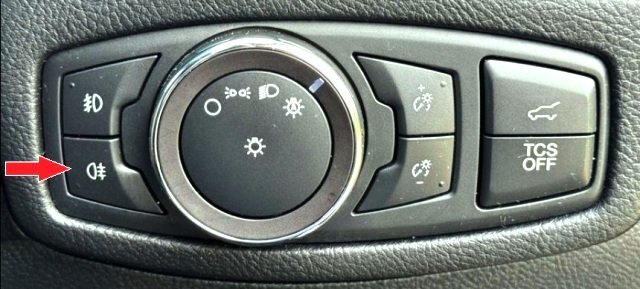
-
Web-searching the part number may yield lower pricing... Link to this FordParts webpage Good luck!


-
** TSB 24-2319 has been superceded by TSB 25-2070, which is posted immediately below ** TECHNICAL SERVICE BULLETIN FHEV - Illuminated MIL With DTCs P0300, P0316 And/Or P051B Stored In The PCM 24-2319 08 October 2024 Model: Lincoln 2024 Nautilus Issue: Some 2024 Nautilus vehicles equipped with a FHEV powertrain may exhibit an illuminated MIL with DTCs P0300, P0316 and/or P051B stored in the PCM. This may be due to the software level of the PCM. To correct this condition, follow the Service Procedure to reprogram the PCM to the latest software level via the FDRS. Action: Follow the Service Procedure to correct the condition on vehicles that meet all of the following criteria: • 2024 Nautilus equipped with an FHEV powertrain • Illuminated MIL with DTC P0300, P0316 and/or P051B stored in the PCM Warranty Status: Eligible under provisions of New Vehicle Limited Warranty (NVLW)/Emissions Warranty/Service Part Warranty (SPW)/Service Part New Vehicle (SPNV)/Extended Service Plan (ESP) coverage. Limits/policies/prior approvals are not altered by a TSB. NVLW/Emissions Warranty/SPW/SPNV/ESP coverage limits are determined by the identified causal part and verified using the OASIS part coverage tool. Labor Times Description Operation No. Time 2024 Nautilus FHEV: Retrieve DTCs And Reprogram The Appropriate Modules As Required By The Software Update And Service Procedure (Do Not Use With Any Other Labor Operations) MT242319 Actual Time Repair/Claim Coding Causal Part: RECALEM Condition Code: 04 Service Procedure 1. Connect a battery charger such as Rotunda GRX-3590 or DCA-8000 to the 12-volt battery. NOTE: To prevent the battery saver mode from activating on the vehicle, make sure the negative cable of the charger is installed on a chassis or engine ground, and not the 12-volt battery negative terminal. Do not have the vehicle plugged into high voltage battery charger during programming. This can cause incorrect module programming. Make sure only the 12-volt battery charger is installed. 2. Reprogram the PCM and SOBDMC using the latest level software level of the FDRS scan tool. Follow all on-screen instructions carefully to complete all coordinated module software updates. NOTE: Advise the customer this vehicle is equipped with an adaptive transmission shift strategy which allows the vehicle's computer to learn the transmission's unique parameters and improve shift quality. When the adaptive strategy is reset, the computer will begin a relearning process. This relearning process may result in firmer than normal upshifts and downshifts for several days. © 2024 Ford Motor Company All rights reserved. NOTE: The information in Technical Service Bulletins is intended for use by trained, professional technicians with the knowledge, tools, and equipment to do the job properly and safely. It informs these technicians of conditions that may occur on some vehicles, or provides information that could assist in proper vehicle service. The procedures should not be performed by "do-it-yourselfers". Do not assume that a condition described affects your car or truck. Contact a Ford or Lincoln dealership to determine whether the Bulletin applies to your vehicle. Warranty Policy and Extended Service Plan documentation determine Warranty and/or Extended Service Plan coverage unless stated otherwise in the TSB article. The information in this Technical Service Bulletin (TSB) was current at the time of printing. Ford Motor Company reserves the right to supersede this information with updates. The most recent information is available through Ford Motor Company's on-line technical resources.
- 1 reply
-
- 1
-
-
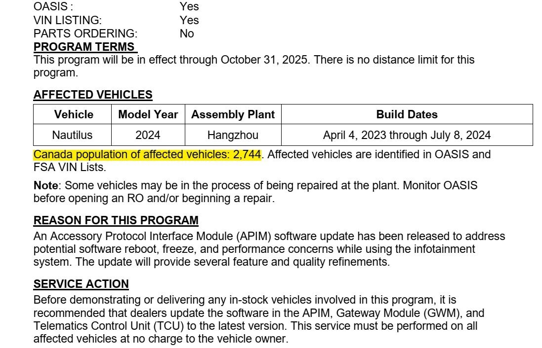
SSM 53041 2024 Nautilus - Front Exterior Farewell Grille Lighting Event Randomly Occurring 30-60 Minutes After The Vehicle Is Parked - Built On Or Before 01-May-2024 Some 2024 Nautilus vehicles built on or before 01-May-2024 may exhibit a front exterior farewell grille lighting event randomly occuring 30-60 minutes after the vehicle is parked. This may be due to the software in the lighting driver control module (LDCM). To address this condition, reprogram the LDCMA (LH headlamp) and LDCMB (RH headlamp) using the Ford Diagnosis and Repair System (FDRS) > Lighting Driver Control Module Software Updates. For claiming, use causal part 13008 and applicable labor operations in section 10 of the Service Labor Time Standards (SLTS) manual. Optionally, claim additional programming (AP) time as needed.
- 1 reply
-
- 2
-
-
Just in case removing the Steering Column trim shroud is necessary to access Connector C2434. In this UK Edge Workshop Manual section, LH Drive is pictured, RH Drive similar, attached below as PDF document... Good luck! Steering Column Shrouds - Removal and Installation - 2017 Edge UK Workshop Manual.pdf
-
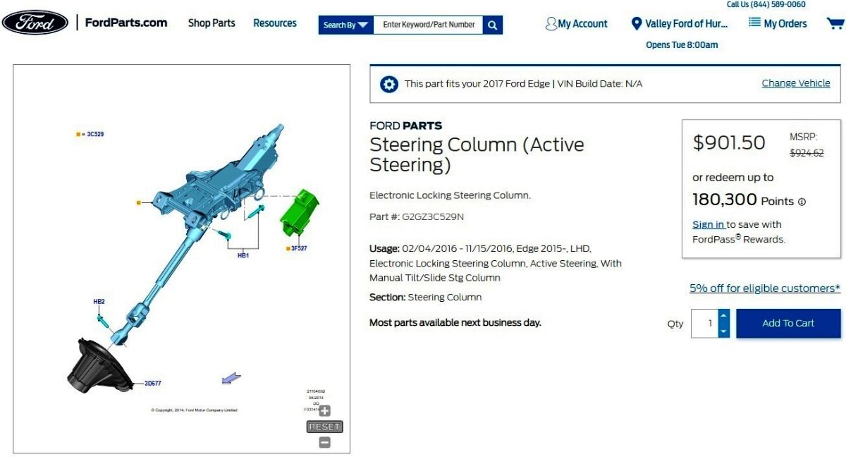
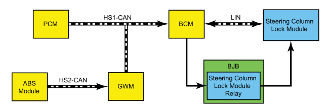
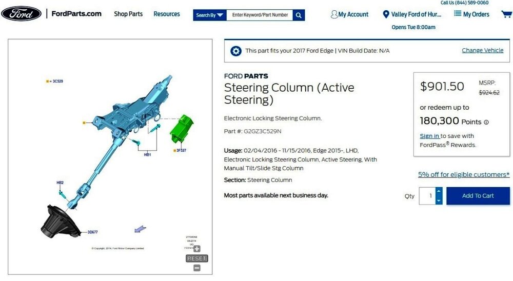
From the 2017 Edge UK Workshop Manual... System Diagram - Steering Column Lock (if equipped) Network Message Chart - Steering Column Lock (if equipped) BCM Network Input Messages Broadcast Message Originating Module Message Purpose Engine rpm data PCM Provides the BCM with the engine speed to indicate if the engine is running or not. Wheel rotation count ABS module Provides the BCM with the vehicle speed to indicate if the vehicle is moving or stationary. Steering Column Lock (if equipped) The steering column lock is used to deter vehicle theft by electronically locking the steering column. This prevents the steering wheel from being rotated to turn the front wheels. The steering column unlocks when: the passive entry feature is used to open the driver door. the driver door is opened after unlocking the vehicle with a RKE transmitter. the START/STOP button is pressed and a valid programmed passive key is detected. the remote start feature is activated. The steering column locks after: the ignition is turned off and 45 seconds have elapsed since the delayed accessory feature has turned off. 45 seconds have elapsed since the remote feature turned off the vehicle. The BCM controls the voltage provided to the steering column lock module using a relay (located in the BJB ) and communicates with it over a LIN . The BCM monitors inputs from various systems to determine when to send a command to lock or unlock the steering column. The steering column lock module locks and unlocks the steering column as directed by commands received from the BCM . If the BCM detects a fault from the steering column lock module or the LIN , the BCM prevents the vehicle from starting. The BCM does not provide power to the steering column lock module when the vehicle is moving or the engine is running. Steering Column Lock Messages (if equipped) The message center displays a message when the BCM detects a fault from the steering column lock module. The "Steering Malfunction" message displays when a fault with the electronic steering column lock system is present and must be diagnosed. The "Turn the wheel while starting" message displays when the steering column lock module is unable to unlock the steering column because of a high amount of torque against the lock (such as when the wheels are against a curb when the vehicle is shut off). The torque against the steering column lock must be relieved for the steering column to unlock. Turn the vehicle off, rotate and hold the steering wheel in one direction while turning the vehicle on. If the message displays again, turn the vehicle off, rotate and hold the steering wheel in the other direction while turning the vehicle on. Component Description Steering Column Lock Module (if equipped) The steering column lock module locks and unlocks the steering column based on commands received from the BCM . The steering column lock module monitors the position of the steering column lock and, if a fault is detected, reports the failure to the BCM . When the steering column lock module is replaced, the BCM must configured/trained to the new steering column lock module for the steering column lock module to operate correctly. The BCM sets a DTC if a fault is detected with the steering column lock module. Additionally, if the BCM is not configured to the steering column lock module, the steering column module keeps the column locked, a programming and/or configuration DTC sets and the vehicle does not start. BCM DTC Chart DTC Description Action B1026:04 Steering Column Lock: System Internal Failure DIAGNOSE all other Diagnostic Trouble Codes (DTCs) present. If no other Diagnostic Trouble Codes (DTCs) are present, INSTALL a new steering column lock module. REFER to: Steering Column Lock Module (211-05 Steering Wheel and Column Electrical Components, Removal and Installation). CARRY OUT the BCM to ESCL (Electronic Steering Column Lock Training) procedure. REFER to: Anti-Theft Key Programming - Scan Tool (419-01B Passive Anti-Theft System (PATS) - Vehicles With: Keyless Vehicle System, General Procedures). B1026:05 Steering Column Lock: System Programming Failure CARRY OUT the BCM to ESCL (Electronic Steering Column Lock Training) procedure. REFER to: Anti-Theft Key Programming - Scan Tool (419-01B Passive Anti-Theft System (PATS) - Vehicles With: Keyless Vehicle System, General Procedures). B1026:09 Steering Column Lock: Component Failure INSTALL a new steering column lock module. REFER to: Steering Column Lock Module (211-05 Steering Wheel and Column Electrical Components, Removal and Installation). CARRY OUT the BCM to ESCL (Electronic Steering Column Lock Training) procedure. REFER to: Anti-Theft Key Programming - Scan Tool (419-01B Passive Anti-Theft System (PATS) - Vehicles With: Keyless Vehicle System, General Procedures). B1026:49 Steering Column Lock: Internal Electronic Failure INSTALL a new steering column lock module. REFER to: Steering Column Lock Module (211-05 Steering Wheel and Column Electrical Components, Removal and Installation). CARRY OUT the BCM to ESCL (Electronic Steering Column Lock Training) procedure. REFER to: Anti-Theft Key Programming - Scan Tool (419-01B Passive Anti-Theft System (PATS) - Vehicles With: Keyless Vehicle System, General Procedures). B1026:51 Steering Column Lock: Not Programmed CARRY OUT the BCM to ESCL (Electronic Steering Column Lock Training) procedure. REFER to: Anti-Theft Key Programming - Scan Tool (419-01B Passive Anti-Theft System (PATS) - Vehicles With: Keyless Vehicle System, General Procedures). B1026:56 Steering Column Lock: Invalid / Incompatible Configuration CARRY OUT the BCM to ESCL (Electronic Steering Column Lock Training) procedure. REFER to: Anti-Theft Key Programming - Scan Tool (419-01B Passive Anti-Theft System (PATS) - Vehicles With: Keyless Vehicle System, General Procedures). B1026:77 Steering Column Lock: Commanded Position Not Reachable INSTALL a new steering column lock module. REFER to: Steering Column Lock Module (211-05 Steering Wheel and Column Electrical Components, Removal and Installation). CARRY OUT the BCM to ESCL (Electronic Steering Column Lock Training) procedure. REFER to: Anti-Theft Key Programming - Scan Tool (419-01B Passive Anti-Theft System (PATS) - Vehicles With: Keyless Vehicle System, General Procedures). B1026:87 Steering Column Lock: Missing Message GO to Pinpoint Test L B1026:92 Steering Column Lock: Performance or Incorrect Operation GO to Pinpoint Test L B1026:93 Steering Column Lock: No Operation DIAGNOSE all other Diagnostic Trouble Codes (DTCs) present. If no other Diagnostic Trouble Codes (DTCs) are present, INSTALL a new steering column lock module. REFER to: Steering Column Lock Module (211-05 Steering Wheel and Column Electrical Components, Removal and Installation). CARRY OUT the BCM to ESCL (Electronic Steering Column Lock Training) procedure. REFER to: Anti-Theft Key Programming - Scan Tool (419-01B Passive Anti-Theft System (PATS) - Vehicles With: Keyless Vehicle System, General Procedures). B1026:96 Steering Column Lock: Component Internal Failure INSTALL a new steering column lock module. REFER to: Steering Column Lock Module (211-05 Steering Wheel and Column Electrical Components, Removal and Installation). CARRY OUT the BCM to ESCL (Electronic Steering Column Lock Training) procedure. REFER to: Anti-Theft Key Programming - Scan Tool (419-01B Passive Anti-Theft System (PATS) - Vehicles With: Keyless Vehicle System, General Procedures). PINPOINT TEST L: THE STEERING COLUMN IS ALWAYS OR NEVER LOCKED (IF EQUIPPED) NOTICE: Use the correct probe adapter(s) when making measurements. Failure to use the correct probe adapter(s) may damage the connector.L1 CHECK FOR VOLTAGE TO THE STEERING COLUMN LOCK MODULE Ignition OFF. Disconnect Steering Column Lock Module C2434. Ignition ON. Measure: Positive Lead Measurement / Action Negative Lead C2434 Pin 2 Ground Is the voltage greater than 11 volts? Yes GO to L4 No VERIFY BJB fuse 48 (15A). If not OK, REFER to the Wiring Diagrams manual to identify the possible causes of the circuit short. If OK, GO to L2 L2 CHECK THE STEERING COLUMN LOCK MODULE RELAY COIL CONTROL CIRCUIT FOR AN OPEN Ignition OFF. Disconnect BJB C1035A. Disconnect BCM C2280C. Measure: Positive Lead Measurement / Action Negative Lead C1035A Pin 33 C2280C Pin 9 Is the resistance less than 3 ohms? Yes GO to L3 No REPAIR the circuit. L3 CHECK THE STEERING COLUMN LOCK MODULE RELAY VOLTAGE SUPPLY CIRCUIT FOR AN OPEN Ignition OFF. Measure: Positive Lead Measurement / Action Negative Lead C1035A Pin 41 C2434 Pin 2 Is the resistance less than 3 ohms? Yes INSTALL a new BJB relay module. No REPAIR the circuit. L4 CHECK THE STEERING COLUMN LOCK MODULE VOLTAGE SUPPLY CIRCUIT FOR A SHORT TO VOLTAGE Disconnect BJB C1035A. Ignition ON. Measure: Positive Lead Measurement / Action Negative Lead C2434 Pin 2 Ground Is any voltage present? Yes REPAIR the circuit. No GO to L5 L5 CHECK THE STEERING COLUMN LOCK MODULE GROUND CIRCUIT FOR AN OPEN Ignition OFF. Measure: Click to display connectors Positive Lead Measurement / Action Negative Lead C2434 Pin 3 Ground Is the resistance less than 3 ohms? Yes GO to L6 No REPAIR the circuit. L6 CHECK THE STEERING COLUMN LOCK MODULE LIN (LOCAL INTERCONNECT NETWORK) CIRCUIT FOR A SHORT TO VOLTAGE Disconnect BCM C2280G. Ignition ON. Measure: Click to display connectors Positive Lead Measurement / Action Negative Lead C2434 Pin 4 Ground Is any voltage present? Yes REPAIR the circuit. No GO to L7 L7 CHECK THE STEERING COLUMN LOCK MODULE LIN (LOCAL INTERCONNECT NETWORK) CIRCUIT FOR A SHORT TO GROUND Ignition OFF. Measure: Click to display connectors Positive Lead Measurement / Action Negative Lead C2434 Pin 4 Ground Is the resistance greater than 10,000 ohms? Yes GO to L8 No REPAIR the circuit. L8 CHECK THE STEERING COLUMN LOCK MODULE LIN (LOCAL INTERCONNECT NETWORK) CIRCUIT FOR AN OPEN Measure: Click to display connectors Positive Lead Measurement / Action Negative Lead C2434 Pin 4 C2280G Pin 25 Is the resistance less than 3 ohms? Yes INSTALL a new steering column lock module. CARRY OUT the BCM to ESCL (Electronic Steering Column Lock Training) procedure. REFER to: Anti-Theft Key Programming - Scan Tool (419-01B Passive Anti-Theft System (PATS) - Vehicles With: Keyless Vehicle System, General Procedures). TEST the system for normal operation. If the concern is still present, GO to L9 No REPAIR the circuit. L9 CHECK FOR CORRECT BCM (BODY CONTROL MODULE) OPERATION Disconnect and inspect all BCM connectors. Repair: corrosion (install new connector or terminals - clean module pins) damaged or bent pins - install new terminals/pins pushed-out pins - install new pins as necessary Reconnect the BCM connectors. Make sure they seat and latch correctly. Operate the system and determine if the concern is still present. Is the concern still present? Yes CHECK OASIS for any applicable Technical Service Bulletins (TSBs). If a TSB exists for this concern, DISCONTINUE this test and FOLLOW TSB instructions. If no Technical Service Bulletins (TSBs) address this concern, INSTALL a new BCM . REFER to: Body Control Module (BCM) (419-10 Multifunction Electronic Modules, Removal and Installation). CARRY OUT the BCM to ESCL (Electronic Steering Column Lock Training) procedure. REFER to: Anti-Theft Key Programming - Scan Tool (419-01B Passive Anti-Theft System (PATS) - Vehicles With: Keyless Vehicle System, General Procedures). No The system is operating correctly at this time. The concern may have been caused by module connections. ADDRESS the root cause of any connector or pin issues. Link to zoomable/scrollable exploded view illustration in below part-listing for LH Drive North American Edge, where green component is the module, to assist you toward locating its connector C2434 ... Relevant Workshop Manual, Wiring & Connector information attached below as PDF documents. Good luck! Diagnostic Pinpoint Test L - Steering Column Is Always or Never Locked - 2017 Edge NA Workshop Manual.pdf Steering Column Lock Module - Connector C2434 Location - 2017 Edge UK.pdf Steering Column Lock Module - Wiring Diagram - 2017 Edge UK.pdf Steering Column Lock Module - Power Distribution Wiring Diagram - 2017 Edge UK.pdf Steering Column Lock Module - Connector C2434 Pin-Circuit Details - 2017 Edge UK.pdf BATTERY JUNCTION BOX (BJB) - Connector C1035A Pin-Circuit Details - 2017 Edge.pdf BODY CONTROL MODULE (BCM) - Connector C2280C Pin-Circuit Details - 2017 Edge.pdf BODY CONTROL MODULE (BCM) - Illustration Showing Connector C2280C Location - 2017 Edge.pdf
-
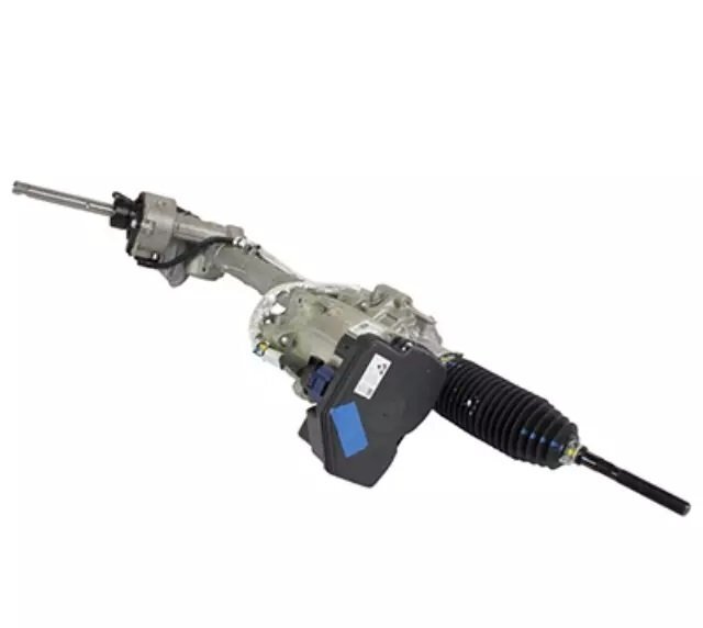
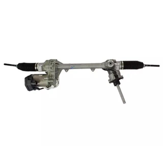
I agree, and I too, just found 2017 Edge Steering Gear photos... I also found a possible PSCM part number on a VIN-specific report, via Ford's UK Professional Technician System (PTS) website: F1GC-3F964-BA. It is possible that then current Service replacement has a different part number, so consulting with your local Ford Works dealer is necessary. Just for awareness, you could verify the part number, cost and availability, though the only DTC thus far is no communication -- which can involve connector, wiring, ground faults. If a DTC for internal failure of the module was present, it would be clear-cut that investing in a new PSCM is the right option -- presuming it's available apart from the Steering Gear assembly. I'll supply that VIN-specific report to you via Forum messaging. Good luck!
-
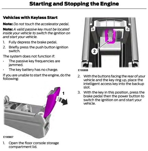
From the 2015 Edge Owner's Manual, page 152... Good luck!
-
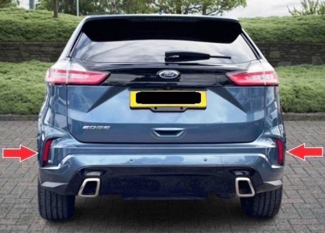
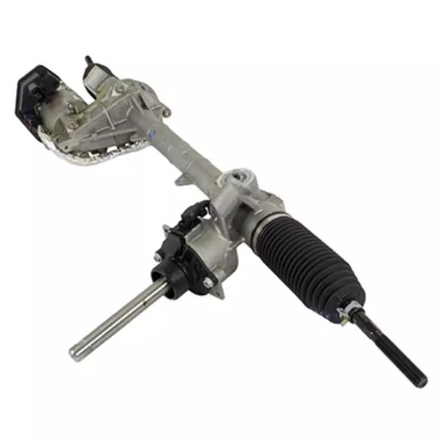
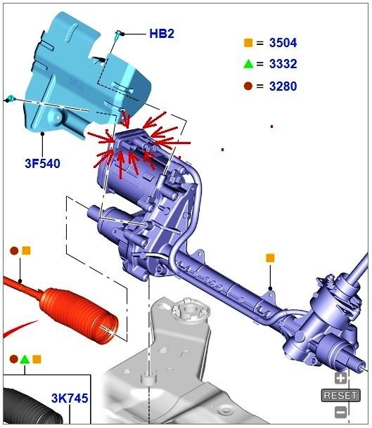
You will need at least a temporarily licensed copy of Forscan to reprogram a new PSCM with the appropriate As-Built data, which you can either copy from the currently installed PSCM, or verify that the PSCM contains the programing values shown in the As-Built Reprograming Data listing that I provided via Forum messaging. If you refer to the Module Configuration Workshop Manual document, the numerical line address for the PSCM will be shown in the table of various modules. Regarding a PSCM part number, I have not yet been able to find a replacement part number listed. I'm aware that the Steering Gear Removal and Installation Workshop Manual document indicates the PSCM provided with a new Steering Gear assembly must be appropriately programed with As-Built values obtained from the prior PSCM before it is removed. To me, this indicates the PSCM is provided in the assembly (PIA) replacing the faulty Steering Gear. On the other hand, one of the diagnostic procedures indicates "Replace the PSCM" as if the module can be separately obtained and is replaceable on the Steering Gear assembly, but again, I've not found a Service part number for the PSCM. Working from illustrations and based upon the depicted connector receptacles, I expect the PSCM is located in the area bounded by red arrows here... etho The full view of this cropped illustration is zoomable and scrollable using your web browser here. Neither the UK nor the North American Edge Workshop Manuals include any PSCM removal and installation procedure, which is unusual. If your diagnostic effort indicates PSCM replacement, then hopefully, inspecting your Edge's Steering Gear may yield a part number stickered or printed on its PSCM, along with some obvious module-mounting fasteners. Lacking Workshop Manual guidance, the question remains of how the PSCM interfaces with the Steering Gear assembly -- unless it's only via the laterally installed harness shown in the Steering Gear illustration, likely containing a C1463A or C1463B connector . Good luck!
-
Doors don't unlock when you grab the handle
Haz replied to nate39's topic in Alarms, Keyless Entry, Locks & Remote Start
From the 2020 Edge Workshop Manual with emphasis added… Passive Entry (if equipped) NOTE: To perform an accurate diagnosis of a concern, make sure the vehicle has a fully charged 12V battery and is in good condition when performing any electrical pinpoint tests. When the vehicle’s 12-volt battery is below a set threshold, certain features can be limited or become inoperative and lead to misdiagnosis. Battery Load Shed The main purpose of controlling electrical consumption with a load management strategy is to: Limit battery discharge Monitor the battery charge status Because of the symptom your Edge is exhibiting – only the driver door passive unlock sensor is operative – you may want to have your Edge’s battery professionally checked at your neighborhood auto parts store, or by a specialty battery seller, or by your dealer’s Service department -- if you prefer. Your Edge’s battery State Of Charge and/or Battery Voltage output may be invoking the vehicle’s Battery Load Shed strategy, resulting in the deactivation of the other three doors’ passive entry sensors. An alternative course of action involves the following description… Door Passive Entry With a programmed passive key within 1 m (3.28 ft) outside a door, touch the lock or unlock sensor on the exterior door handle. The doors lock or unlock depending upon which sensor was touched on the handle. The unlock button is located on the inside of the handle and the lock button is located on the outside top face of the handle. The driver front door passive entry feature either unlocks the driver door (if 2-Stage Unlock is enabled) or all four doors (if 2-Stage Unlock is disabled). The passive entry feature always locks all four doors when the lock button is touched. The remaining doors passive entry feature always locks or unlocks all four doors. While that final sentence suggests otherwise, you may want to first try the following procedure, to attempt to toggle the 2-Stage Unlock enabled/disabled status -- to see if it makes any difference in the operation of driver door passive entry sensor upon all four doors… Staged Unlock Programming - Activation With the ignition in OFF, press the LOCK and UNLOCK buttons on the RKE transmitter simultaneously for 4 seconds. The turn signals flash twice to indicate the mode change. Repeat these steps to enable/disable the staged unlocking feature. If this procedure makes no difference in the operation of the driver door passive unlock sensor, then have your Edge's battery tested to ensure it is not the root cause of your Edge's unlocking symptom. If your Edge's battery tests as Good, then there are other more-technical diagnostic tests to assess what may be causing the unlocking issue -- which you may wish to undertake personally if you're technically capable and materially equipped, or, you may prefer to have your dealer's Service department conduct further diagnostic efforts and to correct the unlocking issue. Please let us know the interim outcome and if you wish to receive additional guidance. Good luck!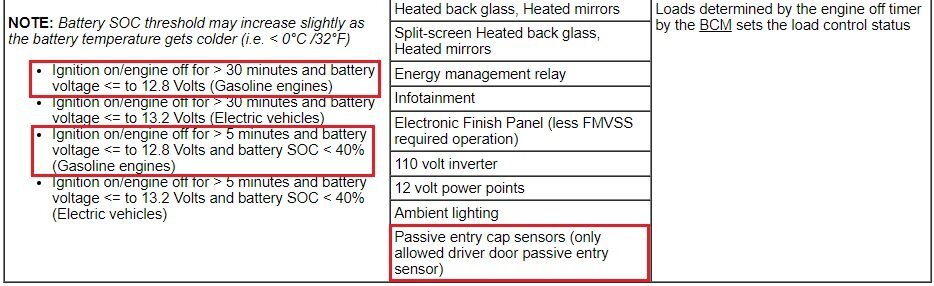

-
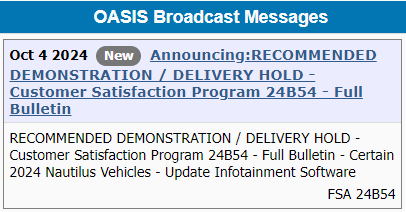
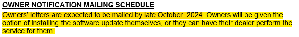
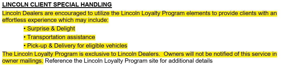
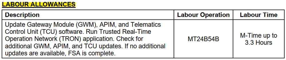
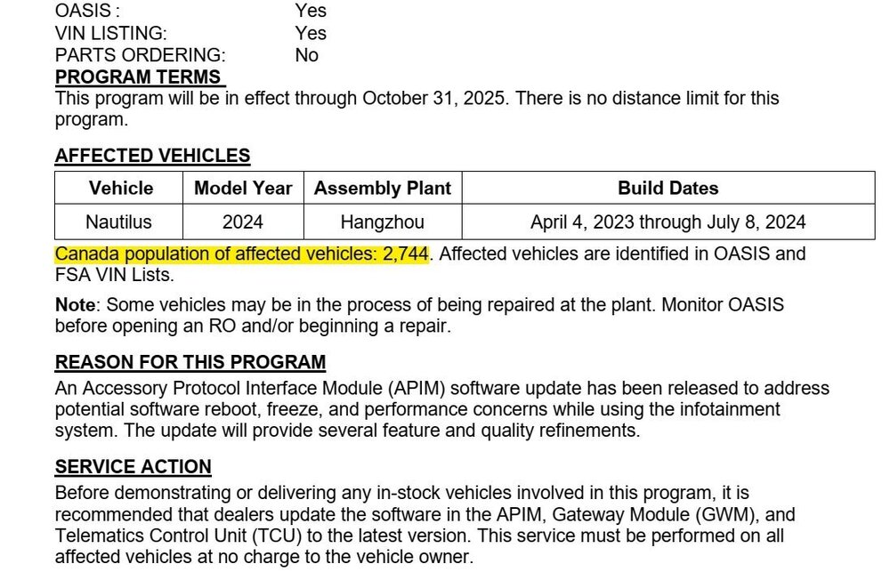
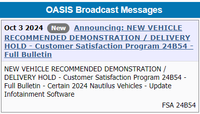
Ford of Canada's Customer Satisfaction Program 24B54 Announcement and Dealer Bulletin details...


-
This is the first reference to Trusted Real-Time Operating Network (TRON) that I've seen. I'm aware that an update to the Ford Diagnosis and Repair System (FDRS) was recently released. so TRON may be a new app running within FDRS used to perform certain tasks. The name suggests that it facilitates communication, so hopefully, FDRS diagnostics and module updates have been improved. Good luck!
-
Because the earlier repair effort involved the PSCM connector(s), you may want to examine them to ensure they are fully seated on the Steering Gear-mounted Module. If they are fully seated, disconnect them and inspect for corrosion and/or for any pins that may have become pushed back inside the connector, and which could cause lost communication with the PSCM. If subsequent scans reveal DTCs involving other modules, let me know here, and I'll provide additional Pinpoint Tests, which may involve checking circuit wiring for shorts or interruptions -- which the past repair efforts may have been pursuing. Good luck!
-
Additional... Good luck! Power Steering Control Module (PSCM) - Connector 1463A location, on Steering Gear Assembly - 2017 Edge UK.pdf
-
Welcome to the Forum @Ryan UK Edge 2017! I understand from our Forum messaging that the new-to-you 2017 Edge presently is exhibiting locked steering with a scanner-revealed DTC U0131, indicating lost communication with the EPAS Steering Gear's Power Steering Control Module (PSCM). Your Edge's vehicle history shows a related-repair effort recorded in Ford's Professional Technician System (PTS) in February 2024, about which you will eventually seek additional local feedback. In the meantime, because of your personal technical capability and your need to move your Edge to a safer location, attached below and in an immediately following post are Workshop Manual and Wiring references in PDF format, to assist you toward fully diagnosis and possible correction of your Edge's locked steering... Power Steering - Vehicles With Active Steering - Overview - 2017 Edge UK Workshop Module.pdf Power Steering - Vehicles With Active Steering - System Operation and Component Description - 2017 Edge UK Workshop Manual.pdf Module Configuration - Operation and Description - 2017 Edge UK Workshop Manual.pdf Steering Gear - Removal and Installation - 2017 Edge UK Workshop Manual.pdf Power Steering Control Module (PSCM) - Wiring Diagram - 2017 Edge UK.pdf Active (Adaptive) Steering - Steering Angle & Effort Control Modules - Wiring Diagram - 2017 Edge UK.pdf Battery Junction Box (BJB) - Top View Illustration - Showing Fuse-Relay-Connector Locations - 2017 Edge UK.pdf Battery Junction Box (BJB) - Bottom View Illustration - Showing Fuse-Relay-Connector Locations - 2017 Edge UK.pdf Battery Junction Box (BJB) - High Current Illustration - Showing Protected Circuits & Fuse Locations - 2017 Edge UK.pdf Battery Junction Box (BJB) - Fuse-Circuits Legend 1 - 2017 Edge UK.pdf Battery Junction Box (BJB) - Fuse-Circuits Legend 2 - 2017 Edge UK.pdf BJB-High Current BJB - Location - 2017 Edge UK.pdf Diagnostic Pinpoint Test F - Lost Communication With PSCM Concern - 2017 Edge North America Workshop Manual.pdf EPAS - DTC & Symptoms Charts With Pinpoint Test Titles Listing - 2017 Edge North America Workshop Manual.pdf EPAS Steering Gear - Enhanced Illustration - 2017 Edge UK Workshop Manual.pdf POWER STEERING CONTROL MODULE (PSCM) - Connector 1463A Circuit-Pin Details - 2017 Edge UK.pdf POWER STEERING CONTROL MODULE (PSCM) - Connector 1463B Circuit-Pin Details - 2017 Edge UK.pdf POWER STEERING CONTROL MODULE (PSCM) - Connector 1463B Location - 2017 Edge.pdf
-
Welcome to the Forum @Ryan UK Edge 2017! I've sent you a Forum message regarding your several Forum posts. Good luck!
- 1 reply
-
- 1
-
-
Removing Center Armrest 2016 Edge Sport
Haz replied to Gary P's topic in Interior, A.C., Heat, Interior Trim
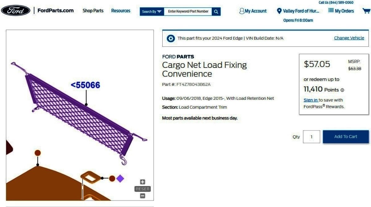
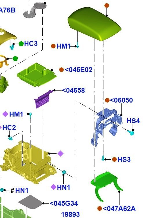
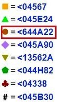
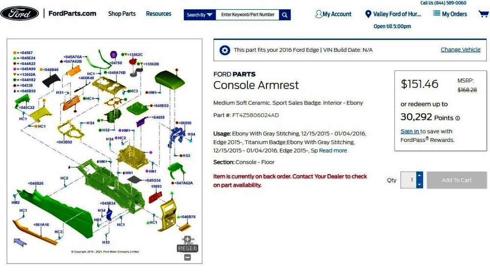
Welcome to the Forum @Gary P! The 2016 Edge Workshop Manual section on the Center Console, attached below as a PDF document, doesn't provide any procedure relating to the Center Armrest and offers only this peripheral illustration... Ford's parts-selling website provides an exploded view of Center Console components... Link to this FordParts webpage ...providing color coded icons that denote components provided in assemblies (PIA), such as for the red-boxed legacy part # for the Center Armrest assembly... Hopefully, viewing your Edge Sport's armrest along with this version of the exploded view illustration, which can be fully zoomed and scrolled in your web browser, may provide you fuller insight into the disassembly effort you seek to accomplish. Good luck! Floor Console - Removal and Installation - 2016 Edge Workshop Manual.pdf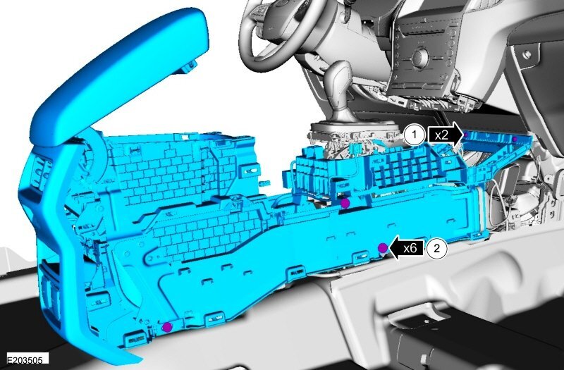
-
SSM 53018 2021-2024 Various Vehicles - DTCs U2100 And/Or U3002 Stored In CCM, SODL, SODR, SODCMC, And/Or SODCMD Some 2021-2024 Ford and Lincoln vehicles may exhibit diagnostic trouble codes (DTCs) U2100 and/or U3002 stored in the cruise control module (CCM), side obstacle detection control module LH (SODL), side obstacle detection control module RH (SODR), side obstacle detection control module C (SODCMC) and/or side obstacle detection control module D (SODCMD) after a module replacement. DTC U2100 may set when the module has not been properly configured after replacement. DTC U3002 may set when the module has been configured with the incorrect VIN. To correct this condition, verify that the module storing the DTC has been installed following the applicable Workshop Manual (WSM) Removal and Installation procedure. If the DTC is still stored, download and run the Vehicle Identification Number (VIN) Write application found under Toolbox, Multi-Module tab in the Ford Diagnosis and Repair System (FDRS). Module Configuration information from the Workshop Manual... Placing your device cursor over underlined acronyms may yield popup full-words descriptions of acronyms. Programmable Module Installation (PMI) PMI is a diagnostic scan tool process which configures settings in a new module. Data used for the PMI process is automatically downloaded from the original module and stored when a diagnostic scan tool session is started. If this data cannot be retrieved from the module being replaced, the diagnostic scan tool may prompt for Configuration data entry or display a list of parameter values that need to be manually selected. Some modules are reprogrammed during PMI when a strategy/calibration update is available. It is important the diagnostic scan tool identifies the vehicle and obtains configuration data prior to removing any modules. The new module must be able to communicate with the diagnostic scan tool in order to carry out PMI . Module Reprogramming Module reprogramming (also referred to as flashing) is a diagnostic scan tool process which updates the strategy/calibration in a module. Reprogramming a module with the same level of software does not improve module operation or repair a hardware failure. Module reprogramming is automatically carried out during PMI when a later strategy/calibration is available. Limit module reprogramming to circumstances where a published TSB , GSB , SSM or FSA recommends doing so. A module cannot communicate with other modules on the communication network while being reprogrammed. After the reprogramming process, clear any network communication Diagnostic Trouble Codes (DTCs) which may have been set in other modules. Some modules are reprogrammed in coordination with other modules. The following modules with an Ethernet connection can be reprogrammed using a diagnostic scan tool and USB flash drive: APIM , GWM and TCU . Programmable Parameters Programmable parameters are customer preference items that may be modified by the dealer via the diagnostic scan tool, or in some cases, modified by the customer following a procedure listed in the Owner Literature. While many configuration options may exist for a module, only a few of these options are programmable parameters. Some parameters must be changed in multiple modules at the same time. Adaptive Learning and Calibration Some modules require a separate learning procedure be carried out if replaced as part of a repair procedure. For adaptive learning and calibration instructions, refer to the specific module removal and installation procedures. Direct Configuration Data (formerly known as VID block) The direct configuration data commonly stores powertrain configuration items such as tire size, axle ratio, and whether or not the vehicle is equipped with cruise control. Configuration data is a VIN -specific module configuration record. During vehicle build, the configuration from all modules is downloaded and stored in the configuration database. Configuration data does not reflect customer preference items that have been changed from the default state. These items need to be changed using programmable parameters after the module is configured. It is not necessary to obtain configuration data unless directed to do so by the diagnostic scan tool. This data may be accessed from the PTS web site. VIN-specific (As-Built) module configuration is also available from this Ford Service website after you designate your Country and Language.
-
The Program was announced today on PTS...

-KT4Z15A448B-FordParts_com.jpg.8c50043a2e43070b4e94a776875f6587.jpg)