Haz
-
Posts
1,568 -
Joined
-
Last visited
-
Days Won
439
Content Type
Profiles
Forums
Gallery
Everything posted by Haz
-
Welcome to the Forum @Dan_o! The VIN-based As-Built data for your Edge's factory installed Audio Front Control Module (ACM) is... 727-01-01 1801 3808 0089 727-01-02 0200 33 727-02-01 5B8C 727-03-01 3C6E 727-04-01 0001 0155 53DD If the currently installed ACM is truly faulty, and it is replaced with a working ACM from an Edge with an identical audio system, then the incoming ACM is likely programmed with the same As-Built values shown above. It would be prudent to verify these As-Built values using Forscan on the currently installed ACM, and to verify the As-Built values of the replacement ACM after it is installed. It is worth noting that a no-audio-sound condition can be caused by a properly working ACM which shuts down audio output in response to a shorted speaker circuit, per the 2017 Edge Workshop Manual, with emphasis added... Symptom Chart: Speakers Condition Possible Sources Actions No sound from all speakers Refer to the Pinpoint Test GO to Pinpoint Test F No Sound From All Speakers Normal Operation and Fault Conditions REFER to: Information and Entertainment System - System Operation and Component Description (415-00B Information and Entertainment System - General Information - Vehicles With: Touchscreen Display, Description and Operation). See ACM . When the ignition status message from the BCM indicates that the engine is cranking, the ACM mutes the audio output. A short to ground or short to voltage in the circuitry to one of the speakers may cause multiple speakers to lose sound due to the built-in overload protection feature of the ACM . In this case, a speaker fault DTC sets. DTC Fault Trigger Conditions DTC Description Fault Trigger Conditions DTC Type B1142:27 Ignition Status 1: Signal Rate of Change Above Threshold Set by the ACM when an error is detected in the ignition status message from the BCM during engine start. Continuous Possible Source ACM PINPOINT TEST F: NO SOUND FROM ALL SPEAKERS F1 VERIFY THAT THE ACM (AUDIO FRONT CONTROL MODULE) PASSES THE NETWORK TEST Using a diagnostic scan tool, perform the network test. Did the ACM pass the network test? Yes GO to F2 No REFER to: Communications Network (418-00 Module Communications Network, Diagnosis and Testing). See The ACM Does Not Respond To The Diagnostic Scan Tool. F2 CHECK FOR SPEAKER DIAGNOSTIC TROUBLE CODES (DTCS) Ignition ON. Using a diagnostic scan tool, perform the ACM self-test. Are any speaker fault Diagnostic Trouble Codes (DTCs) present? Yes REFER to the ACM DTC Chart in this section. ***INCLUDED BELOW THIS PINPOINT TEST*** No GO to F3 F3 CHECK FOR CORRECT ACM (AUDIO FRONT CONTROL MODULE) OPERATION Ignition OFF. Disconnect and inspect all the ACM connectors and related in-line connectors. Repair: corrosion (clean module pins or install new connectors or terminals) damaged or bent pins (install new terminals or pins) pushed-out pins (install new pins as necessary) Reconnect the ACM connectors and related in-line connectors. Make sure they seat and latch correctly. Operate the system and determine if the concern is still present. Is the concern still present? Yes CHECK OASIS for any applicable Technical Service Bulletins (TSBs). If a TSB exists for this concern, discontinue this test and follow TSB instructions. If no Technical Service Bulletins (TSBs) address this concern, INSTALL a new ACM . REFER to: Audio Front Control Module (ACM) (415-00B Information and Entertainment System - General Information - Vehicles With: Touchscreen Display, Removal and Installation). No The system is operating correctly at this time. The concern may have been caused by module connections. ADDRESS the root cause of any connector or pin issues. DTC Chart: ACM DTC Description Action B1142:27 Ignition Status 1: Signal Rate of Change Above Threshold GO to Pinpoint Test F B1A01:01 Speaker #1: General Electrical Failure For a LHF door speaker concern, GO to Pinpoint Test G For a LHF tweeter speaker concern, GO to Pinpoint Test H B1A01:11 Speaker #1: Circuit Short To Ground For a LHF door speaker concern, GO to Pinpoint Test G For a LHF tweeter speaker concern, GO to Pinpoint Test H B1A01:12 Speaker #1: Circuit Short To Battery For a LHF door speaker concern, GO to Pinpoint Test G For a LHF tweeter speaker concern, GO to Pinpoint Test H B1A01:13 Speaker #1: Circuit Open For a LHF door speaker concern, GO to Pinpoint Test G For a LHF tweeter speaker concern, GO to Pinpoint Test H B1A02:01 Speaker #2: General Electrical Failure For a RHF door speaker concern, GO to Pinpoint Test I For a RHF tweeter speaker concern, GO to Pinpoint Test J B1A02:11 Speaker #2: Circuit Short To Ground For a RHF door speaker concern, GO to Pinpoint Test I For a RHF tweeter speaker concern, GO to Pinpoint Test J B1A02:12 Speaker #2: Circuit Short To Battery For a RHF door speaker concern, GO to Pinpoint Test I For a RHF tweeter speaker concern, GO to Pinpoint Test J B1A02:13 Speaker #2: Circuit Open For a RHF door speaker concern, GO to Pinpoint Test I For a RHF tweeter speaker concern, GO to Pinpoint Test J B1A03:01 Speaker #3: General Electrical Failure For a RHR door speaker concern, GO to Pinpoint Test K For a RHR tweeter speaker concern, GO to Pinpoint Test L B1A03:11 Speaker #3: Circuit Short To Ground For a RHR door speaker concern, GO to Pinpoint Test K For a RHR tweeter speaker concern, GO to Pinpoint Test L B1A03:12 Speaker #3: Circuit Short To Battery For a RHR door speaker concern, GO to Pinpoint Test K For a RHR tweeter speaker concern, GO to Pinpoint Test L B1A03:13 Speaker #3: Circuit Open For a RHR door speaker concern, GO to Pinpoint Test K For a RHR tweeter speaker concern, GO to Pinpoint Test L B1A04:01 Speaker #4: General Electrical Failure For a LHR door speaker concern, GO to Pinpoint Test M For a LHR tweeter speaker concern, GO to Pinpoint Test N B1A04:11 Speaker #4: Circuit Short To Ground For a LHR door speaker concern, GO to Pinpoint Test M For a LHR tweeter speaker concern, GO to Pinpoint Test N B1A04:12 Speaker #4: Circuit Short To Battery For a LHR door speaker concern, GO to Pinpoint Test M For a LHR tweeter speaker concern, GO to Pinpoint Test N B1A04:13 Speaker #4: Circuit Open For a LHR door speaker concern, GO to Pinpoint Test M For a LHR tweeter speaker concern, GO to Pinpoint Test N B1A06:02 Speaker #6: General Signal Failure GO to Pinpoint Test O B1A06:11 Speaker #6: Circuit Short To Ground GO to Pinpoint Test O B1A06:12 Speaker #6: Circuit Short To Battery GO to Pinpoint Test O B1A06:13 Speaker #6: Circuit Open GO to Pinpoint Test O B1A56:21 Antenna: Signal Amplitude < Minimum If DTC B1A56:21 sets after running the bezel diagnostic tests, DISREGARD this DTC . This test is used for end of line or repair bay testing at the Ford plant. Each plant has its own assigned frequency and signal strength requirements. The running and passing of this test depends on local radio stations. If no local station is broadcasting on the required frequency, the test will fail. B1A89:11 Satellite Antenna: Circuit Short To Ground For a satellite radio concern, GO to Pinpoint Test B For a SIRIUS Travel Link concern, GO to Pinpoint Test C For a navigation concern (if equipped), GO to Pinpoint Test AB For a compass concern, GO to Pinpoint Test AC B1A89:13 Satellite Antenna: Circuit Open For a satellite radio concern, GO to Pinpoint Test B For a SIRIUS Travel Link concern, GO to Pinpoint Test C For a navigation concern (if equipped), GO to Pinpoint Test AB For a compass concern, GO to Pinpoint Test AC B1D19:49 Compact Disc Unit: Internal Electronic Failure GO to Pinpoint Test Y B1D19:4B Compact Disc Unit: Over Temperature GO to Pinpoint Test Y U0100:00 Lost Communication With ECM/PCM "A": No Sub Type Information GO to Pinpoint Test AE U0140:00 Lost Communication With Body Control Module: No Sub Type Information GO to Pinpoint Test AF U0155:00 Lost Communication With Instrument Panel Cluster (IPC) Control Module: No Sub Type Information GO to Pinpoint Test AH U0253:00 Lost Communication With Accessory Protocol Interface Module: No Sub Type Information GO to Pinpoint Test AI U0256:00 Lost Communication With Front Controls Interface Module “A”: No Sub Type Information GO to Pinpoint Test AJ U0257:00 Lost Communication With Front Controls / Display Interface Module: No Sub Type Information GO to Pinpoint Test AK U201A:51 Control Module Main Calibration Data: Not Programmed This DTC sets due to an incomplete or incorrect ACM PMI . CHECK the vehicle service history for recent service actions related to the ACM . If there have been recent service actions with the ACM , INSTALL As-Built data from Professional Technician Society (PTS), following the diagnostic scan tool instructions under Module Programming>As-Built. REFER to: Module Configuration - System Operation and Component Description (418-01 Module Configuration, Description and Operation). If there have been no recent service actions, the ACM has failed to retain configuration data. INSTALL a new ACM . REFER to: Audio Front Control Module (ACM) (415-00A Information and Entertainment System - General Information - Vehicles With: AM/FM/CD/SYNC, Removal and Installation). U2100:00 Initial Configuration Not Complete: No Sub Type Information This DTC sets due to an incomplete or incorrect ACM PMI . CHECK the vehicle service history for recent service actions related to the ACM . If there have been recent service actions with the ACM , INSTALL As-Built data from Professional Technician Society (PTS), following the diagnostic scan tool instructions under Module Programming>As-Built. REFER to: Module Configuration - System Operation and Component Description (418-01 Module Configuration, Description and Operation). If there have been no recent service actions, the ACM has failed to retain configuration data. INSTALL a new ACM . REFER to: Audio Front Control Module (ACM) (415-00A Information and Entertainment System - General Information - Vehicles With: AM/FM/CD/SYNC, Removal and Installation). U2101:00 Control Module Configuration Incompatible: No Sub Type Information This DTC sets due to an incomplete or incorrect ACM PMI . CHECK the vehicle service history for recent service actions related to the ACM . If there have been recent service actions with the ACM , INSTALL As-Built data from Professional Technician Society (PTS), following the diagnostic scan tool instructions under Module Programming>As-Built. REFER to: Module Configuration - System Operation and Component Description (418-01 Module Configuration, Description and Operation). If there have been no recent service actions, the ACM has failed to retain configuration data. INSTALL a new ACM . REFER to: Audio Front Control Module (ACM) (415-00A Information and Entertainment System - General Information - Vehicles With: AM/FM/CD/SYNC, Removal and Installation). U3000:41 Control Module: General Checksum Failure CLEAR the DTC . WAIT at least 10 seconds. REPEAT the self-test. If DTC U3000:41 is retrieved again, INSTALL a new ACM . REFER to: Audio Front Control Module (ACM) (415-00A Information and Entertainment System - General Information - Vehicles With: AM/FM/CD/SYNC, Removal and Installation). U3000:42 Control Module: General Memory Failure CLEAR the DTC . WAIT at least 10 seconds. REPEAT the self-test. If DTC U3000:42 is retrieved again, INSTALL a new ACM . REFER to: Audio Front Control Module (ACM) (415-00A Information and Entertainment System - General Information - Vehicles With: AM/FM/CD/SYNC, Removal and Installation). U3000:96 Control Module: Component Internal Failure CLEAR the DTC . WAIT at least 10 seconds. REPEAT the self-test. If DTC U3000:96 is retrieved again, INSTALL a new ACM . REFER to: Audio Front Control Module (ACM) (415-00A Information and Entertainment System - General Information - Vehicles With: AM/FM/CD/SYNC, Removal and Installation). U3003:16 Battery Voltage: Circuit Voltage Below Threshold GO to Pinpoint Test AL U3003:17 Battery Voltage: Circuit Voltage Above Threshold GO to Pinpoint Test AM If Forscan reveals any Diagnostic Trouble Codes (DTCs) present in the ACM that require additional Pinpoint Test diagnostics, report back here and I will supply any needed Test(s). Related Workshop Manual sections are attached below as PDF documents... Good luck! Information and Entertainment System - 9-Speaker System Operation and Component Description - 2017 Edge Workshop Manual.pdf Information and Entertainment System - 9-Speaker System Component Location - 2017 Edge Workshop Manual.pdf Information and Entertainment System - Bezel Diagnostics - 2017 Edge Workshop Manual.pdf Audio Front Control Module (ACM) - Removal and Installation - 2017 Edge Workshop Manual.pdf Front Display Interface Module (FDIM) - Removal and Installation - 2017 Edge Workshop Manual.pdf Front Controls Interface Module (FCIM) - Removal and Installation - 2017 Edge Workshop Manual.pdf 2017 Edge Workshop Manual - Module Configuration - System Operation and Component Description.pdf
-
Engine Coolant Over Tempreture ERROR
Haz replied to NelsonPM33's topic in Interior, A.C., Heat, Interior Trim
@NelsonPM33: Just print the PDF documents, print this discussion, and then provide it all to your Mechanic, who's job it is to deal with the complexity of your Edge's issue. Good luck!- 4 replies
-
- 1
-

-
- engine coolant over temp
- 2.7 ecoboost
- (and 2 more)
-
Lane Keeping Assistant won't turn off!
Haz replied to Rchalk's topic in Interior, A.C., Heat, Interior Trim
@Rchalk: When ACC was mentioned, I should have recognized your Edge was equipped with Co-Pilot360+... Good luck!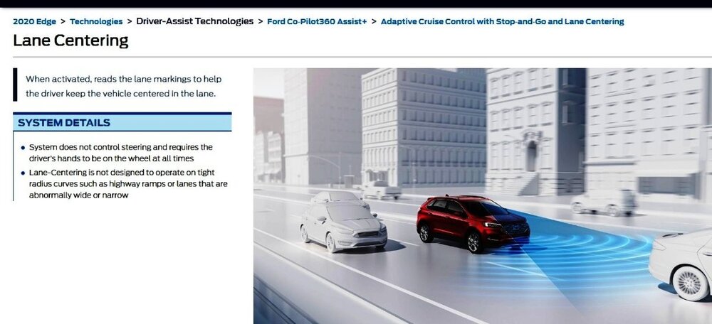

-
Lane Keeping Assistant won't turn off!
Haz replied to Rchalk's topic in Interior, A.C., Heat, Interior Trim
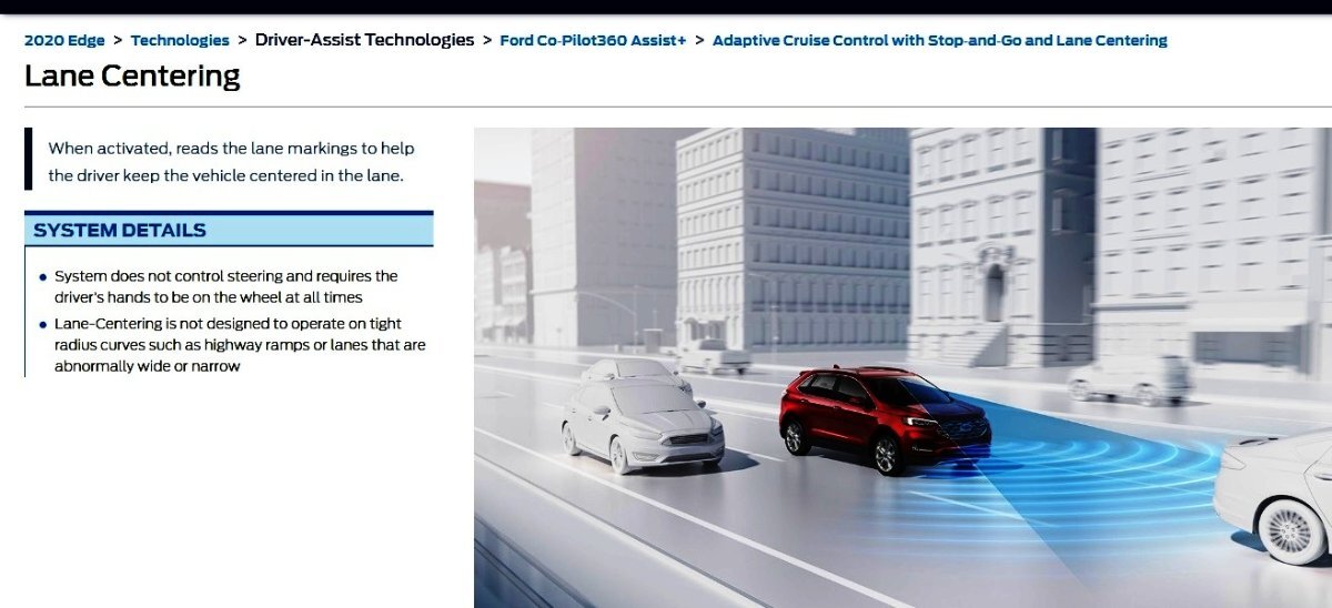
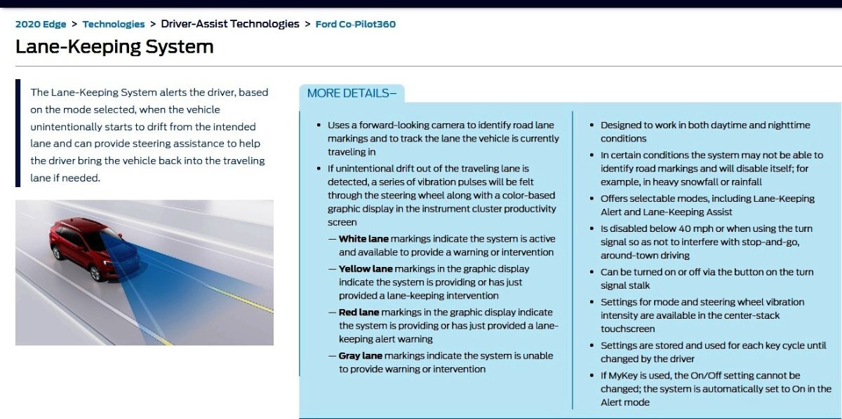
From the 2020 Edge Workshop Manual with emphasis added... Lane Keeping System Operation The lane keeping system is turned on and off using the lane keeping system switch located on the LH steering column multifunction switch. The lane keeping system switch is directly connected to the SCCM . The last known on/off setting for the lane keeping system is recalled every time the key is turned on. When a MyKey® is in use, the system defaults the lane keeping alert mode to on and cannot be turned off. When the system is on, it is active only when the vehicle speed is above 64 km/h (40 mph) and at least one lane marking can be detected by the camera. The system can be turned off at any time by pressing the lane keeping system switch. If the lane keeping system switch is pressed when a MyKey® is in use, the IPC message center will display a message informing the driver that the system is on. Looking to the above MyKey references - If you have more than one key, for your Edge, is the Lane Keeping System (LKS) on/off behavior issue the same for each key? Looking to the above last known on/off setting reference - If you deactivate ACC and then shut down your Edge, and then you restart the vehicle and activate ACC, is the LKS then On or Off? Toward your desire to perform a LKS reset - The Image Processing Module A (IPMA) power is protected by Body Control Module fuse F36 15-amp, which also protects the Auto Dimming Interior Mirror and Heated Rear Seat Module LH circuits. LKS Workshop Manual sections and Wiring/Fuse diagrams are attached below as PDF documents... Good luck! Lane Keeping System - System Operation and Component Description - 2020 Edge Workshop Manual.pdf Lane Keeping System - Overview - 2020 Edge Workshop Manual.pdf Lane Keeping System - Component Location - 2020 Edge Workshop Manual.pdf Image Processing Module A (IPMA) - Power Distribution Wiring Diagram - 2020 Edge.pdf Body Control Module (BCM) - Fuse Location Illustration - 2020 Edge.pdf Body Control Module (BCM) - Fuse-Circuits Legend - 2020 Edge.pdf Lane Keeping System (LKS) - Diagnostic Trouble Code (DTC) & Symptom Charts - 2020 Edge Workshop Manual.pdf 2020 Edge Settings & MyKey.pdf

-
Welcome to the Forum @Maso125! From the below-attached 2007 Edge Workshop Manual procedure, with emphasis added... Cooling System Filling and Bleeding NOTICE: Use the vacuum cooling system filler to fill the cooling system, then carry out the remaining steps to bleed all the air from the cooling system. Failure to follow these instructions can leave air in the cooling system which may damage the engine or cooling system. Good luck! Cooling System Draining, Filling and Bleeding - General Procedures - 2007 Edge Workshop Manual.pdf
-
Welcome to the Forum @Traumajunkie46! From the 2016 Edge Workshop Manual, attached below as PDF documents... Good luck! Ignition Coil-On-Plug - Removal and Installation - 3.5L Duratec - 2016 Edge Workshop Manual.pdf Air Cleaner Outlet Pipe - Removal and Installation - 3.5L Duratec - 2016 Edge Workshop Manual.pdf Engine Overview - Description and Operation - 3.5L Duratec - 2016 Edge Workshop Manual.pdf Upper Intake Manifold - Removal and Installation - 3.5L Duratec - 2016 Edge Workshop Manual.pdf Quick Release Coupling - General Procedures - 3.5L Duratec - 2016 Edge Workshop Manual.pdf
-
Welcome to the Forum @tiggerose! From the 2017 Edge Workshop Manual, attached below as a PDF document... Good luck! Loadspace Trim Panel Cargo Net Hook - Removal and Installation - 2017 Edge Workshop Manual.pdf
-
@BMWR1200c: For your technical awareness, attached below as PDF documents... Good luck! Rain Sensor - Removal and Installation - 2020 Edge Workshop Manual.pdf Image Processing Module A (IPMA) - Removal and Installation - 2020 Edge Workshop Manual.pdf
-
SSM 53099 - 2024 Nautilus - Autofold Mirrors Inoperative After Performing FSA 24C24 Some 2024 Nautilus customers may notice the side mirror autofold feature inoperative after FSA 24C24 has been completed. This may be due to the feature defaulting to off after the driver door module (DDM) and passenger door module (PDM) software has been updated per the FSA. If this concern occurs it may be necessary to turn this feature back on in the vehicle. To regain the auto-fold power mirror function, go to Apps (icon with six dots on the left side of the center display screen) > Settings > Vehicle > Mirrors > Autofold and if the setting is turned off toggle it on. If the setting is already on, toggle it off then back on. Do this for each personal profile that has been set up in the vehicle including the guest profile. For information on the referenced Field Service Action (FSA) 24C24, see... Compliance Recall 24C24 - Certain 2024 Nautilus + Ranger - Power Windows May Pinch - Software Update to Driver & Passenger Door Modules
-
Related information attached below as PDF documents... Good luck! Halogen Headlamps - BCM to Lamps Wiring Diagram - 2012 Edge.pdf HEADLAMP, LEFT - Connector C1021A Pin-Circuit Details - 2012 Edge.pdf HEADLAMP, RIGHT - Connector C1041A Pin-Circuit Details - 2012 Edge.pdf HEADLAMP, RIGHT - Ground G107 Location - 2012 Edge.pdf Ground G107 - Wiring Diagram - 2012 Edge.pdf
-
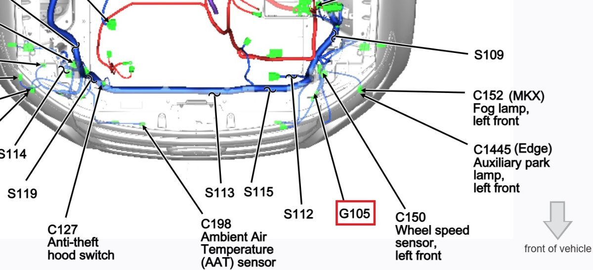
Welcome to the Forum @Superhawk! Additional informational attached below as PDF documents... Good luck! Ground G105 Location - Left Front Between S112 & C150 In Illustration - 2012 Edge.pdf Ground G105 - Wiring Diagram - 2012 Edge.pdf

-
Engine Coolant Over Tempreture ERROR
Haz replied to NelsonPM33's topic in Interior, A.C., Heat, Interior Trim
Welcome to the Forum @NelsonPM33! Your 2016 Edge Sport is equipped with a virtual Engine Coolant Gauge... ...which the 2016 Edge Workshop Manual describes as operating in this way with emphasis added... Placing your device cursor over underlined acronyms may yield popup full-words descriptions of the acronyms. Virtual Temperature Gauge The IPC uses 2 messages to control the temperature gauge. The first is the engine coolant temperature data, which provides the current engine temperature input to the PCM . The second message is the engine overheat indication request, which is sent by the PCM to the IPC when an overheating condition exists. When the IPC receives the engine overheat indication request message, the IPC sends the temperature gauge to full hot and turns on the over-temperature warning indicator. The IPC receives all the temperature gauge inputs from the GWM over the HS-CAN3 . The GWM receives the engine coolant temperature data and the engine overheat indication request messages from the PCM over the HS-CAN1 . If the engine coolant temperature data or engine overheat indication request messages are missing for less than 5 seconds, the IPC defaults the temperature gauge to the last indication state, based upon the last message received. If the engine coolant temperature data or engine overheat indication request messages are missing for 5 seconds or longer, the IPC defaults the temperature gauge to the full hot position. The following diagnostic Pinpoint Test B provides guidance on scanning your Edge's virtual-gauge-involved electronic modules for Diagnostic Trouble Codes (DTCs) that may describe the root cause of possible missing engine coolant data messages that are defaulting your Edge's virtual temperature gauge to full hot / overheated condition... A Virtual Gauge (AWD , Tachometer Or Temperature), Is Inoperative Normal Operation and Fault Conditions See Temperature Gauge. REFER to: Instrument Panel Cluster (IPC) - System Operation and Component Description (413-01 Instrumentation, Message Center and Warning Chimes, Description and Operation). ***ATTACHED AT BOTTOM OF THIS POST*** Temperature Gauge If the engine coolant temperature data or engine overheat indication request messages are missing for less than 5 seconds, the IPC defaults the temperature gauge to the last indication state, based upon the last message received. If the engine coolant temperature data or engine overheat indication request messages are missing for 5 seconds or longer, the IPC defaults the temperature gauge to the full hot position. Possible Sources Communication concern GWM concern PCM input concern IPC PINPOINT TEST B: A VIRTUAL GAUGE (AWD (ALL-WHEEL DRIVE) , TACHOMETER OR TEMPERATURE), IS INOPERATIVE B1 VERIFY THE IPC (INSTRUMENT PANEL CLUSTER) IS SET TO DISPLAY THE GAUGE Ignition ON. NOTE: The IPC and message center navigation can be found in the Owner's Literature. Using the message center controls, make sure the IPC is set to display the gauge in question. Is the IPC set to display the gauge? Yes GO to B2 No The virtual gauge is operating correctly. The IPC was not set to display the gauge in question. B2 PERFORM THE IPC (INSTRUMENT PANEL CLUSTER) SELF-TEST Using a diagnostic scan tool, perform the IPC self-test. Check for recorded Diagnostic Trouble Codes (DTCs) from the IPC self-test. Are any Diagnostic Trouble Codes (DTCs) recorded? Yes REFER to DTC Chart: IPC in this section. No GO to B3 B3 PERFORM THE PCM (POWERTRAIN CONTROL MODULE) SELF-TEST Using a diagnostic scan tool, perform the PCM self-test. Check for recorded Diagnostic Trouble Codes (DTCs). Are any Diagnostic Trouble Codes (DTCs) recorded? Yes Refer to the appropriate section in Group 303for the procedure. No GO to B4 B4 CHECK THE GWM (GATEWAY MODULE A) DIAGNOSTIC TROUBLE CODES (DTCS) Using a diagnostic scan tool, check the GWM Continuous Memory Diagnostic Trouble Codes (DTCs). Are any Diagnostic Trouble Codes (DTCs) recorded? Yes REFER to: Communications Network (418-00 Module Communications Network, Diagnosis and Testing). No Click here to access Guided Routine (IPC). If you don't have immediate access to an electronic scanner DTC code reader, hopefully a local auto parts store or your local Ford dealer may offer that scanning service, but in the meantime, you can perhaps use Dealer Test Mode to see if the Instrument Panel Cluster (IPC) is reporting any current or historical DTCs... Dealer Test Mode NOTE: The table lists the displays as they appear when navigating using the down arrow button. To enter the IPC engineering test mode or dealer test mode, begin with the ignition OFF. Press and hold the LH steering wheel switch OK button. Place the ignition ON and continue to hold the button for 5-8 seconds until the display indicates Test or Gauge Sweep. Press the up or down arrow buttons to navigate through each of the display windows. To exit the IPC dealer test mode, press and hold the OK button for 5-8 seconds or place the ignition in OFF. Each down arrow button press advances the viewing window to the next set of items. IPC Display Description Engineering Test Mode Use Right Up/Down to scroll screens Initial entry display into the dealer test mode. ANALOG GAUGE TEST Carries out the gauge sweep of the analog gauges. When the sweep (zero to maximum then return to zero) is complete, the actual data is displayed. TELLTALE AND COLOR TEST Illuminates all cluster microprocessor controlled LED telltales or indicators. Also displays a color palette of boxes below the title. PartNo: xxxx-xx Core: xxxx-xx Cal#1: xxxx-xx ECU S/W: xxxx-xx Displays the IPC part number information. Man Date: xxxxxx B&A Config Bytes xx xx xx xx xx xx xx xx xx xx Displays the manufacturing information. Date in the format of YYMMDD. B&A configuration bytes DTC: HIST CURR xxxxxx x x xxxxxx x x Displays all of the Diagnostic Trouble Codes (DTCs) set (history and current Diagnostic Trouble Codes [DTCs]). An X in the HIST or CURR column means the DTC is active. Three Diagnostic Trouble Codes (DTCs) display on each screen. If more Diagnostic Trouble Codes (DTCs) are present, there will be additional screens listing them. If there are no Diagnostic Trouble Codes (DTCs) in history or current, the display will only be the title row. Vehicle Speed: xxx.x km/h xxx.x MPH Tach: xxxx RPM NOTE: These are the filtered values used to drive the gauge positions, not the actual positions. Displays the digital representation of the speedometer gauge in mph and km/h. Inst Fuel: xxxx FLPM: xxxx.xx Displays the instant fuel level and filtered fuel level in percent. This is used for a single sender fuel level input. Inst Fuel1: xxxx FLPM: xxxx.xx Displays the instant fuel level and filtered fuel level in percent. This is used for the fuel pump assembly input on a dual sender fuel tank configuration. Inst Fuel2: xxxx FLPM: xxxx.xx Displays the instant fuel level and filtered fuel level in percent. This is used for the fuel level sensor input on a dual sender fuel tank configuration. DTE: Inst 01 Disp km xxx xxx xxx mi xxx xxx xxx Displays the values used for calculating the DTE function. RAFE RAFE_01 xxx.x xxx.x 1/100km xxx.x xxx.x MPG xxx.x xxx.x km/l Displays the running average fuel economy. The values are derived from the DTE function. State Val #ofVS Szero: xxxx xxxx Off: xxxx xxxx On: xxxx xxxx Displays the key ON initialization, key OFF reference, and zero speed reference fuel level values in fuel level for a single sender fuel level input. State Val #ofVS Szero1: xxxx xxxx Off: xxxx xxxx On: xxxx xxxx Displays the key ON initialization, key OFF reference, and zero speed reference fuel level values in fuel level for the fuel pump assembly input on a dual sender fuel tank configuration. State Val #ofVS Szero2: xxxx xxxx Off: xxxx xxxx On: xxxx xxxx Displays the key ON initialization, key OFF reference, and zero speed reference fuel level values in fuel level for the fuel level sensor input on a dual sender fuel tank configuration. Coolant Temp (°C): xxx Displays the digital representation of the coolant temperature gauge indication in degrees Celsius. Odo cnts: xx Trip A: xxxxx.x km Trip A: xxxxx.x mi Displays the values from the odometer count signal and the trip A statistics. Odo cnts: xx Trip B: xxxxx.x km Trip B: xxxxx.x mi Displays the values from the odometer count signal and the trip B statistics. Fuel cnts: xxx Fuel A: xxxxx.x l Fuel A: xxxxx.x g Displays the values of the fuel flow display signal from the PCM and the approximate fuel used for the trip stats A. Fuel cnts: xxx Fuel B: xxxxx.x l Fuel B: xxxxx.x g Displays the values of the fuel flow display signal from the PCM and the approximate fuel used for the trip stats B. Battery: xx.xV Compass: xx Last Chime: xx Displays the current battery level. Displays the compass direction. Displays the number of the last chime sounded. Dim Step: xx Dim Gauge: xxxxx Dim Pointer: xxxxx Displays the first screen of dimming information. Dim step is the dimming level. Dim gauge is the internal illumination number for the gauge backlighting (1 to 10,000). Dim pointer is the internal illumination number for the gauge pointer backlighting (1 to 10,000). Dim Step: xx Dim PRNDL: xxxxx Dim Display: xxxxx Displays the second screen of dimming information. Dim step is dimming level. Dim PRNDL is the internal illumination number for PRNDL backlighting (1 to 10,000). Dim display is the internal illumination number for the display backlighting (1 to 10,000). PDS: x LWS: x Park detect switch (0 = open/not park, 1 = closed/park). Engineering Test Mode Use Right Up/Down to scroll screens Repeats the test display cycle. Please report back here any DTCs that are revealed by a code scanner or Dealer Test Mode, and we'll provide additional guidance. Relevant procedures and wiring & connector information is attached below as PDF documents. Good luck! Instrument Panel Cluster (IPC) - System Operation and Component Description - 2016 Edge Workshop Manual.pdf ENGINE COOLANT TEMPERATURE (ECT) SENSOR - Connector C1016 - Pin-Circuit Details - 2016 Edge.pdf ENGINE COOLANT TEMPERATURE (ECT) SENSOR - Connector C1016 - Location - 2016 Edge.pdf POWERTRAIN CONTROL MODULE (PCM) - Connector C1551E - Pin-Circuit Details - 2016 Edge.pdf POWERTRAIN CONTROL MODULE (PCM) - Connector C1551E -Location - 2016 Edge.pdf POWERTRAIN CONTROL MODULE (PCM) - Removal and Installation - FOR LOCATION ILLUSTRATIONS - 2016 Edge Workshop Manual.pdf Engine Coolant Temperature (ECT) Sensor to Powertrain Control Module (PCM) Wiring Diagram - 2016 Edge.pdf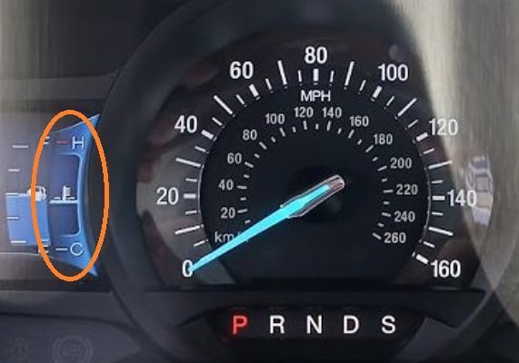
- 4 replies
-
- 3
-
-
- engine coolant over temp
- 2.7 ecoboost
- (and 2 more)
-
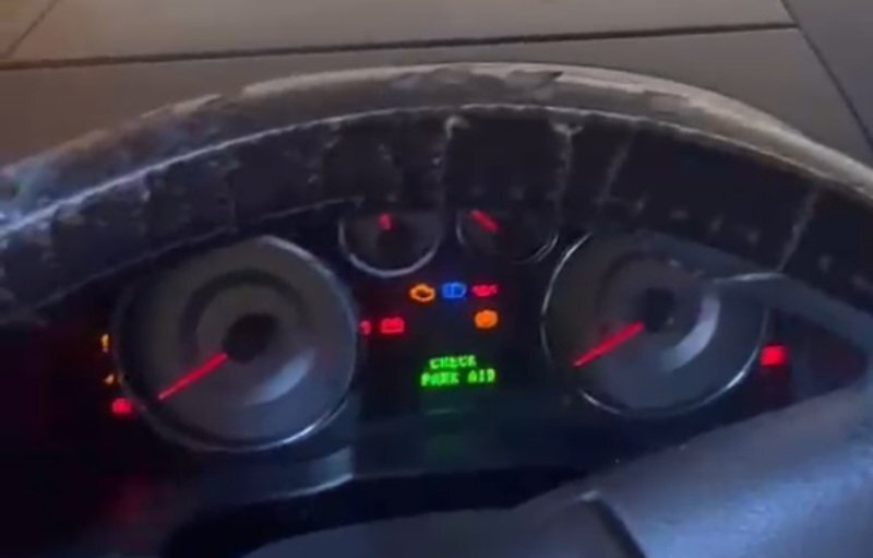
Welcome to the Forum @BrandonS! I suspect the Edge's erratic symptoms may be the result of a failing or failed battery, based upon unexpected behavior of Instrument Cluster warning lights and its Message Center, as shown in the 17-seconds-long stuck-on washer pump video... Have the Edge's battery tested at a reputable battery seller or neighborhood auto parts store. If the battery tests good, then ask if they can scan the Edge's electronic modules for Diagnostic Trouble Codes (DTCs), and report any observed DTCs back here, then we'll provide additional guidance. 2010 Edge Workshop Manual sections relating to Instrument Cluster and Message Center behavior are attached below as PDF documents... Good luck! Instrument Cluster - 2010 Edge Workshop Manual.pdf Instrument Cluster Prove-Out Chart - 2010 Edge Workshop Manual.pdf Information And Message Center - 2010 Edge Workshop Manual.pdf
-
@BMWR1200c: The 2020 Edge Workshop Manual procedures are identical to the above-attached 2022-2024 Edge Workshop Manual procedures. Wheel lug nut torque is contained in the attached PDF document... Good luck! Wheel and Tire - Removal and Installation - 2020 Edge Workshop Manual.pdf
-
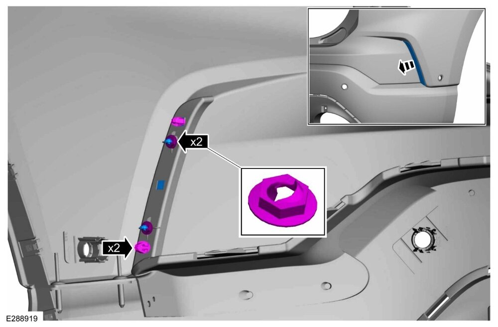
From the 2022-2024 Edge Workshop Manual, and attached below as PDF documents... Good luck! On both sides. Remove the push nuts, release the tabs and remove the rear reflector. Rear Lamp Assembly - Removal and Installation - 2022-2024 Edge Workshop Manual.pdf Rear Bumper Cover - Removal and Installation - 2022-2024 Edge Workshop Manual.pdf Rear Bumper Cover - Disassembly and Assembly - 2022-2024 Edge Workshop Manual.pdf
-
Attached below as PDF documents... Please note that Inline Connector C900 pinout document lacks these circuit descriptions for Module Communications-related pins: Good luck! Inline Connector C900 - Location View 1 - 2022 Edge.pdf Inline Connector C900 - Location View 2 - 2022 Edge.pdf Inline Connector C900 - Location View 3 - 2022 Edge.pdf Inline Connector C900 - Pin-Circuit Alpha-Numeric Identifier - 2022 Edge.pdf


-
Additional information attached below as PDF documents... Please let me know if any observed Diagnostic Trouble Code (DTC) or Symptom(s) indicates any Diagnostic Pinpoint Test(s) that may be useful toward your efforts, and I will supply. Good Luck! Controller Area Network (CAN) Module Communications Network - System Operation and Component Description - 2022 Edge Workshop Manual.pdf Controller Area Network (CAN) Module Communications Network - Diagnosis and Testing - 2022 Edge Workshop Manual.pdf
-
Welcome to the Forum @Jarekmucha! Attached below as PDF documents... Please let me know if you need additional module Connector details. Good Luck! Module Communications Network -Wiring Diagram Page 1 - 2022 Edge.pdf Module Communications Network -Wiring Diagram Page 2 - 2022 Edge.pdf Module Communications Network -Wiring Diagram Page 3 - 2022 Edge.pdf Module Communications Network -Wiring Diagram Page 4 - 2022 Edge.pdf Module Communications Network -Wiring Diagram Page 5 - 2022 Edge.pdf Module Communications Network -Wiring Diagram Page 6 - 2022 Edge.pdf Module Communications Network -Wiring Diagram Page 7 - 2022 Edge.pdf Module Communications Network -Wiring Diagram Page 8 - 2022 Edge.pdf Gateway Module - Connectors C4931A-B-C Location - 2022 Edge.pdf Gateway Module - Connectors C4931A - Pin-Circuit Details - 2022 Edge.pdf Gateway Module - Connector C4931B - Pin-Circuit Details - 2022 Edge.pdf Gateway Module - Connector C4931C - Pin-Circuit Details - 2022 Edge.pdf Remote Data Link Connector (DLC) - Connector C2122 - Pin-Circuit Details - 2022 Edge.pdf Remote Data Link Connector (DLC) - Connector C2122 - Location - 2022 Edge.pdf
-
SSM 53089 - Vehicles Equipped with SYNC4 - Intermittent Symptoms After All Available Software Updates Performed - Awareness of Solutions Being Developed Some vehicles equipped with SYNC4 may exhibit one or more of the following symptoms after all currently available accessory protocol interface module (APIM) software updates have been performed. - General system performance, stability, and intermittent system reboots. - Intermittent Wireless CarPlay or Android Auto function. - Phone related concerns with intermittent No Audio or Static. - Navigation/global positioning system (GPS) related concerns through CarPlay and Android Auto. - Alexa function consistency and stability. These symptoms may be due to the software in the APIM. Replacing the APIM will not resolve these symptoms for the customer. Before returning the vehicle to the customer, review the procedures within Workshop Manual, Section 415-00 and ensure the latest APIM software is installed. Refer to General Service Bulletin (GSB) 23-7146 for help determining the latest available level of software. IMPORTANT: some module software updates will only display as available on Ford Diagnosis and Repair System (FDRS) after prerequisite modules are updated. This may require the technician to update certain modules multiple times during the service visit, before the latest APIM software is accessible in FDRS. If symptoms continue after latest APIM software has been installed, inform customers that Ford is working on additional software enhancements which are expected to be delivered over-the-air (OTA) in Q1 2025. Software will update automatically if vehicle connectivity is enabled in the vehicle's settings. Schedule a service visit for customers who have disabled vehicle connectivity or who report that they did not receive the update in late Q1 2025. Monitor OASIS for additional information.
- 1 reply
-
- 4
-
-

-
Welcome to the Forum @Jim Goldsmith! Presuming you are referring to your Edge's interior mirror, the relevant Workshop Manual section is attached below as a PDF document... Good luck! Interior Rear View Mirror - Removal and Installation - 2020 Edge Workshop Manual.pdf
- 1 reply
-
- 2
-
-
TECHNICAL SERVICE BULLETIN 2.7/3.0L EcoBoost - Engine Oil Leak From The Crankshaft Rear Seal With Retaining Plate 24-2331 23 October 2024 Model: Ford 2021-2024 Bronco Engine: 2.7L EcoBoost Engine: 3.0L EcoBoost 2018-2024 Edge Engine: 2.7L EcoBoost 2020-2025 Explorer Engine: 3.0L EcoBoost 2018-2024 F-150 Engine: 2.7L EcoBoost 2024 Ranger Engine: 2.7L EcoBoost Engine: 3.0L EcoBoost Lincoln 2020-2025 Aviator Engine: 3.0L EcoBoost 2018-2023 Nautilus Engine: 2.7L EcoBoost Issue: Some 2018-2024 F150/Edge, 2018 MKX, 2019-2023 Nautilus, 2020-2025 Explorer/Aviator, 2021-2024 Bronco, and 2024 Ranger vehicles equipped with a 2.7L EcoBoost or a 3.0L EcoBoost engine may exhibit an engine oil leak from the crankshaft rear seal with retaining plate. This may be due to incorrect WSM installation instructions. To correct this condition, use this information along with the Service Procedure located within the WSM, Section 303-01 to correctly replace the crankshaft rear seal with retaining plate. Action: Follow the Service Procedure to correct the condition on vehicles that meet all the following criteria: • One of the following vehicles: - 2018-2024 F150 - 2018-2024 Edge - 2018 MKX - 2019-2023 Nautilus - 2020-2025 Explorer/Aviator - 2021-2024 Bronco - 2024 Ranger • Equipped with one of the following engines: - 2.7L EcoBoost - 3.0L EcoBoost • Engine oil leak coming from the crankshaft rear seal with retaining plate Special Tool(s) Seal Installer, Rear Main 303-1250 Warranty Status: Information Only. Repair/Claim Coding Causal Part: IN Condition Code: -1 Service Procedure Do not attempt to replace the rear crankshaft seal by itself. Order and install the rear crankshaft seal with retaining plate assembly (service base part# 6335). Prior to installing the crankshaft rear seal and retaining plate, the crankshaft surface must be cleaned using a dust-free cloth and Motorcraft® Metal Brake Parts Cleaner. Do not use abrasive materials as this can damage the sealing surface and affect the performance of the rear crankshaft seal. The engine block sealing surface must be completely clean and free of oil and debris in preparation for RTV silicone application. Clean the metal surface as outlined in the RTV Sealing Surface Cleaning and Preparation procedure. Refer to the WSM, Section 303-00 Engine System > General Information, General Procedures > RTV Sealing Surface Cleaning and Preparation. During installation of the crankshaft rear seal and retaining plate onto the crankshaft: • Lubricate the essential special service tool (ESST) outer surface, rear main seal inner surface, and the crankshaft sealing surface with new engine oil. • Once the crankshaft rear seal and retaining plate assembly is in place and during the removal of the ESST, closely inspect for seal roll. If a seal is rolled it will create an oil leak. Refer to Figure 1 for an example of a correctly installed seal, Figure 2 for an example of an incorrectly installed seal that has a partial roll, and Figure 3 for an example of a incorrectly installed seal with a fully rolled seal around the entire sealing surface. • Rear crankshaft seal with retainer plates are one-time-use parts. If the rear crankshaft seal becomes rolled during installation, the rear crankshaft seal with retaining plate assembly must be discarded. Figure 1: Figure 2: Figure 3: © 2024 Ford Motor Company All rights reserved. NOTE: The information in Technical Service Bulletins is intended for use by trained, professional technicians with the knowledge, tools, and equipment to do the job properly and safely. It informs these technicians of conditions that may occur on some vehicles, or provides information that could assist in proper vehicle service. The procedures should not be performed by "do-it-yourselfers". Do not assume that a condition described affects your car or truck. Contact a Ford or Lincoln dealership to determine whether the Bulletin applies to your vehicle. Warranty Policy and Extended Service Plan documentation determine Warranty and/or Extended Service Plan coverage unless stated otherwise in the TSB article. The information in this Technical Service Bulletin (TSB) was current at the time of printing. Ford Motor Company reserves the right to supersede this information with updates. The most recent information is available through Ford Motor Company's on-line technical resources. TSB 24-2331 - 2.7L & 3.0L EcoBoost - Engine Oil Leak From The Crankshaft Rear Seal With Retaining Plate.pdf Crankshaft Rear Seal with Retainer Plate - 2.7L EcoBoost - Removal and Installation - Edge Workshop Manual.pdf
-
@Bunky: True, that. Good luck!
-
@Bunky: If you have not already, you may want to contact your dealer to see if they will perform the update in the absence of the described symptom. They may be able to determine your vehicle's current software level through its Connected Vehicle data reporting. Good luck!
-
January 7, 2025 edit: emphasis added SSM 53064 - 2024 Nautilus - Driver Seat And Steering Column Not Moving To Easy Entry Position After Setting Up A Client Profile Some 2024 Nautilus vehicles may exhibit a concern with the driver seat and steering column moving to the saved memory position instead of the easy entry position when approaching or unlocking the vehicle with the key fob. This condition may occur after setting up a client profile and is due to the driver front seat module (DSM) software. Inform customers that they can continue to drive the vehicle and that engineering is currently working on revised DSM software for this condition that is expected late Q4 2024. In the interim, easy entry will function if the key fob is unlinked from the customers personal profile by selecting the profile on the center display screen, pressing the edit icon, choosing ID Method, pressing Unlink Key Fob, and then selecting Unlink from the pop-up screen. The customers driver seat and steering column memory settings will no longer be saved to the key fob but can be recalled by using the memory switches on the door or on the center display screen. Monitor OASIS for additional information and schedule service appointments for customers once the repair becomes available.
-
General Service Bulletin 24-7110 - Wireless Accessory Charging Module (WACM) Aid To Improve Performance Summary This article is intended to aid dealers and to provide customer recommendations to resolve concerns of the phone indicating a "temperature - cool down prior to using" warning, an inoperative or slow charging, and/or an intermittent charging while using the WACM. Service Information The WACM inductively charges a single Qi 1.x (pronounced "chee") compatible mobile phone at rates of up to 15W of power. Not all phones are compatible with wireless charging and not all phones are compatible with Qi 1.x wireless charging. Specific considerations are: Possible Causes Of A Phone Indicating A "Temperature" Warning Phones naturally warm up when charging wirelessly and might display warnings such as “Phone needs to cool down” which is a phone internal overheating protection mechanism to protect the battery. This is not an indication of WACM malfunction. In addition, using Wireless Apple CarPlay or Android Auto in combination with wireless charging will often heat up the phone faster. The temperature at which each phone will show an overheating message is dependent of the phone’s brand, model, battery health and battery state of charge. Possible Causes Of Inoperative/Slow Or Intermittent Charging When placing a phone on the module, the phone State of Charge may appear to not change, raise slowly, decrease, or charging goes on and off repeatedly. The speed at which each phone charges is dependent on the phone’s brand, model, battery health and battery state of charge. Streaming maps, audio or calls through Wireless Apple Car Play or Wireless Android Auto can also cause slow charging. For additional information, see the full General Service Bulletin attached below as a PDF document... GSB 24-7110 - Wireless Accessory Charging Module (WACM) Aid To Improve Performance - 10-21-2024.pdf