


Haz
-
Posts
1,568 -
Joined
-
Last visited
-
Days Won
439
Content Type
Profiles
Forums
Gallery
Everything posted by Haz
-
@Bunky: Yes, per the relevant section of 2024 Nautilus Workshop Manual, attached below in full as a PDF document, you are correct... Good luck! Placing your device cursor over underlined acronyms may yield full-words descriptions of the acronyms: Push Button Ignition Switch The push button ignition switch is used to control the ignition mode. Refer to the following table for information about achieving the various ignition modes. Ignition Entry Condition Desired Ignition Mode Action To Take Off ON (engine off) Press the START/STOP button without applying the brake pedal. Off or on START Apply the brake pedal and then press the START/STOP button. On (engine off) OFF Press the START/STOP button. On (engine running) OFF Press the START/STOP button. Ignition Mode LED Indicator The ignition mode LED indicates the ignition mode of the vehicle. The BCM controls the voltage to the ignition mode LED indicator. Refer to the following table. Ignition Mode Ignition Mode LED Indicator Off Off On (engine off) Flashing On (engine running) On OFF The BCM controls the relays providing voltage to the vehicle electrical systems. When the ignition is in the ON mode, a single press and release of the START/STOP button (without applying the brake pedal) changes the ignition to the OFF mode. No programmed key is required to change the ignition to the OFF mode when the vehicle is running. If the vehicle is in motion, a momentary press of the START/STOP button does not shut the vehicle off. If the vehicle is moving at a speed greater than 15 km/h (9 mph), the START/STOP button must be pressed and held for longer than one second (or pressed 3 times within 2 seconds) to turn the ignition off. When the BCM changes the ignition mode to OFF, it communicates the ignition mode to the other modules by sending an ignition status message over the CAN . ON When the ignition is in the ON mode, the BCM activates the run/start relay to provide voltage to the vehicle electrical systems and communicates the ignition mode to the other modules by sending an ignition status message over the CAN . When the vehicle enters ON mode, multiple indicators in the IPC prove out and the IPC displays the gear selection and the vehicle mileage. START The vehicle temporarily enters the START mode if the brake pedal is applied when the START/STOP button is pressed, and a valid programmed key is detected within the vehicle. In addition to activating the run/start relay, the BCM communicates the ignition mode to the other modules by sending an ignition status message over the CAN . After the ignition has completed the vehicle start sequence, the ignition mode returns to ON and the ignition mode LED in the START/STOP button illuminates steadily. The engine can be started from any ignition mode. Steering Wheel and Column Electrical Components - System Operation and Component Description - 2024 Nautilus Workshop Manual.pdf
-
2018 edge sel glove box removal
Haz replied to conniepj's topic in Interior, A.C., Heat, Interior Trim
Welcome to the Forum, @conniepj! Blower Motor removal and installation procedure from the 2018 Edge Workshop Manual is attached below as a PDF document... Good luck! Blower Motor - Removal and Installation - 2018 Edge Workshop Manual.pdf -
2020 Power source for trailer light converter
Haz replied to Got 2's topic in Interior, A.C., Heat, Interior Trim
Welcome to the Forum @Got 2! From the 2020 Edge Workshop Manual... Good luck! Loadspace Trim Panel - Removal and Installation - 2020 Edge Workshop Manual.pdf -
From the 2015 Edge Workshop Manual... Good luck! Media Hub - Removal and Installation - 2015 Edge Workshop Manual.pdf
-
No Audio with Replacement AL7T-18K931-AC
Haz replied to Edward Stefan's topic in Audio, Backup, Navigation & SYNC
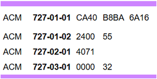
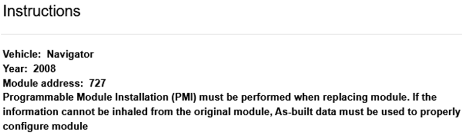
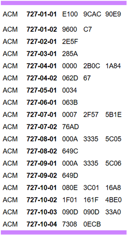
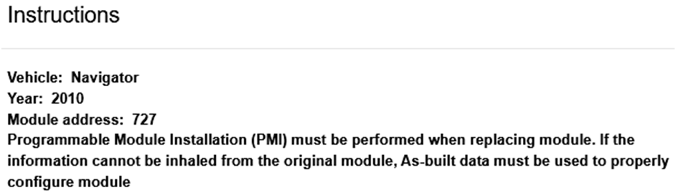
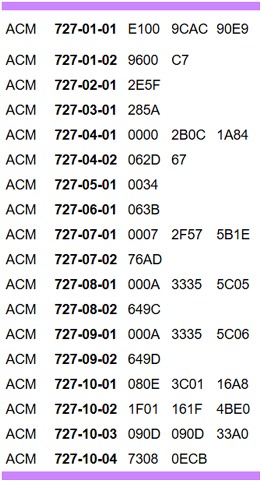
The Ford Expedition Forum is a community of experienced and helpful Expedition & Navigator owners that you may enjoy -- but a long as you're here: Per the Expedition-Navigator Workshop Manual, with emphasis added, the Audio Control Module (ACM) is a configurable component... Principles of Operation Configurable modules accommodate a variety of vehicle options, eliminating the need for many unique modules for one vehicle line. These modules must be configured when replaced as part of a repair procedure. Configurable modules should not be exchanged between vehicles since the settings are unique to each vehicle. Failure to configure a new module may result in improper operation and/or Diagnostic Trouble Codes (DTCs) setting. As-Built Data As-Built data is a VIN specific module configuration record. During vehicle build, the configuration from all modules is downloaded and stored in the As-Built database. NOTE: It is not necessary to obtain As-Built data unless directed to do so by the scan tool. This data may be accessed from the technician service publication website. As-Built datasets for Ford-Lincoln-Mercury vehicles from 1999 to current model years can be obtained from the Ford Service Info website (link), where the user selects and submits Country and Language, and then enters and submits the vehicle's VIN on the next webpage. As-Built data is presented in text format as well as an electronic .ab-format downloadable file. As-Built data for the ACM is contained in Line 727 entries, which are among configuration data for all other of the vehicle's configurable modules. It's worth noting that 2008 Navigators are not equipped with SYNC -- which was introduced on the 2009 Navigator -- so looking at ACM As-Built configuration values for 2008 versus 2010 Model Years reveals a significant difference because of the 2010 ACM's added interaction with the vehicle's SYNC (APIM) Module. Be aware that your 2008 ACM values may not be the same as this VIN-specific 2008 ACM As-Built example... It's likely that your 2010 ACM has set Diagnostic Trouble Codes (DTCs) after its installation in your 2008 Navigator, due to the 2010 ACM looking for -- and not finding -- the expected SYNC (APIM) Module. If the 2010 ACM is returnable, then you may choose send it back because of it's SYNC-capability which your 2008 Navigator lacks. If you cannot return the 2010 ACM, then it may be worth obtaining the As-Built configuration values for your 2008 ACM, either from the module itself using a Scan Tool or Forscan on a device connected to your Navigator's OBDII data port, or, by downloading your Navigator's As-Built dataset from the Ford Service Info site. Then, reprogram the 2010 ACM Line 727 values which correspond to your 2008 Navigator ACM's Line 727 values using a Scan Tool or a device containing a licensed version of Forscan capable of module programing via your Navigator's OBDII data port. Doing this may or may not enable the 2010 ACM to produce joyful noise in your Navigator. Good luck!

-
2016 Ford Edge DTC C1001 Backup Camera
Haz replied to rdavis006's topic in Audio, Backup, Navigation & SYNC
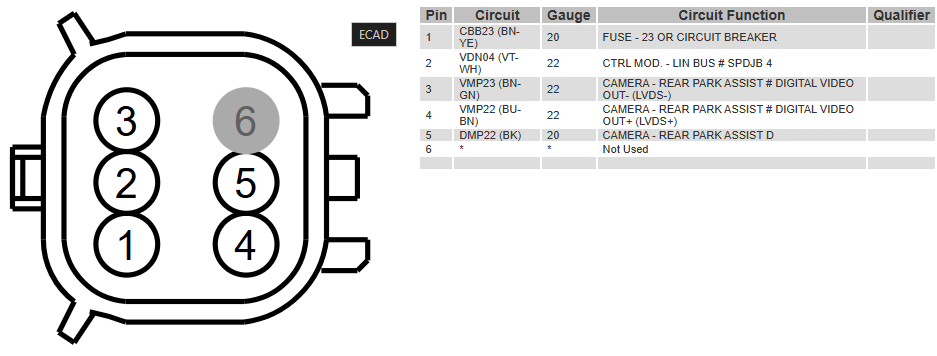
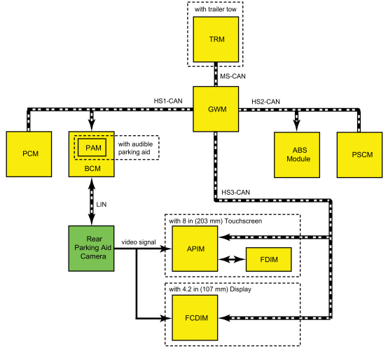
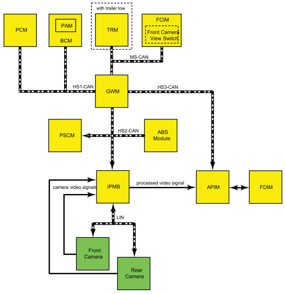
Welcome to the Forum @rdavis006! Echoing @Wubster100, from the 2016 Workshop Manual's final step of the Rear Camera installation procedure: Follow the instructions on the scan tool to configure the rear view camera. If Rear Only Parking Aid Camera LIN Communication The BCM and the rear parking aid camera communicate via a LIN circuit which is a dedicated single wire communication network. The messages sent from the BCM to the camera are: Camera configuration data Display manual zoom request Guideline on/off request Trailer connection status (if equipped with trailer tow) Steering angle Standby enable/disable request The messages sent from the camera to the BCM are: Camera status Display zoom status Camera part number data Guideline status If Front and Rear Parking Aid Cameras LIN Communication The IPMB communicates with the front and rear cameras via a LIN circuit, which is a dedicated single wire communication network. The messages sent from the IPMB to the front and rear cameras are: Camera view request (front camera only) Camera configuration data Display manual zoom request (rear camera only) Guideline on/off request (rear camera only) Trailer connection status (if equipped with trailer tow) Steering angle (rear camera only) Standby enable/disable request The messages sent from the front and rear camera to the BCM are: Camera status Display zoom status (rear camera only) Camera part number data Guideline status (rear camera only) Per your original request: 2016 Edge Rear Camera partial diagnostic Pinpoint Test, with connector pinout and Battery Junction Box (BJB) fuse location... DTC Charts: APIM Pinpoint Test A (Partial) A9 CHECK FOR VOLTAGE TO THE REAR CAMERA Ignition OFF. Disconnect Rear Parking Aid Camera C4357. Ignition ON. Measure: Positive Lead Measurement / Action Negative Lead C4357 Pin 1 Ground Is the voltage greater than 11 volts? Yes GO to A10 No INSPECT BJB fuse 23 (15A). If the fuse is OK, repair the circuit for an open. If the fuse is not OK, REFER to the Wiring Diagrams manual to identify the possible causes of the short circuit. A10 CHECK FOR GROUND AT THE REAR CAMERA Measure: Positive Lead Measurement / Action Negative Lead C4357 Pin 1 C4357 Pin 5 Is the voltage greater than 11 volts? Yes GO to A12 No For vehicles with an 8 in (203 mm) touchscreen, GO to A11 For vehicles with a 4.2 in (107 mm) centerstack infotainment display, REPAIR the circuit. Good luck!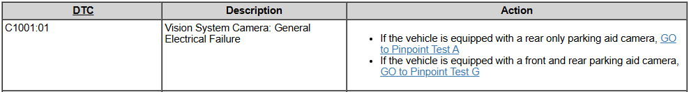

-FuseF23Red-Boxed-2016Edge.thumb.jpg.99be078b9ed9993ee01455a3e1a52ee0.jpg)

-
No Audio with Replacement AL7T-18K931-AC
Haz replied to Edward Stefan's topic in Audio, Backup, Navigation & SYNC
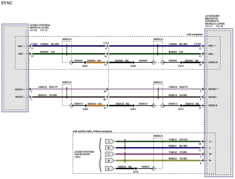
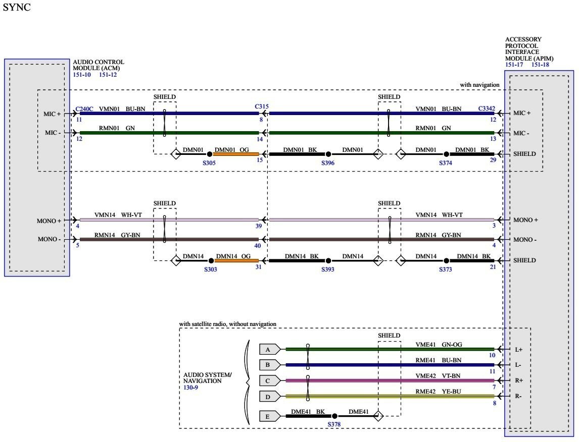
Welcome to the Forum @Edward Stefan! While more information would be useful toward assisting you... Year, Model, and Trim Level of your vehicle and, if known, of the replacement Audio Control Module's (ACM) donor vehicle; Is your vehicle equipped with SYNC; What is the feature level of the original and replacement ACMs, per this description example from the 2008 Edge/MKX Workshop Manual... Audio Line-Up The following audio systems are available: Premium — Edge AM/FM single CD or AM/FM 6-CD changer ACM One speaker in each door Audiophile I — Edge AM/FM 6-CD changer or navigation ACM External audio amplifier (with navigation only) Four 2-way speakers in each door, subwoofer in the RH rear quarter Audiophile II — Edge AM/FM 6-CD changer or navigation ACM External audio amplifier (with navigation only) One mid-woofer in each front door, one 2-way speaker in each rear door, 2 A-pillar speakers, subwoofer in the RH rear quarter Premium — MKX AM/FM 6-CD changer or navigation ACM External audio amplifier (with navigation only) One mid-woofer and tweeter in each front door, one speaker in each rear door THX® sound AM/FM 6-CD changer or navigation ACM Audio Digital Signal Processing (DSP) module (with built-in amplifier) located behind the subwoofer One mid-woofer and tweeter in each front door, one 2-way speaker in each rear door, a 3-in-1 instrument panel speaker, 2 D-pillar speakers, subwoofer in the RH rear quarter Because you mention that your vehicle's current ACM sounds great, perhaps you are upgrading to a THX ACM. If so, you will need to add a Digital Signal Processing (DSP) Module for the THX ACM audio output to be usable by your vehicle's speakers, as show in the attached Wiring Diagrams, attached below as PDF documents... If you need electrical connector pinout diagrams and/or diagnostic Pinpoint Test(s), just let me know. Good luck! Premium-Audiophile Edge - Wiring Diagram - 2008 Edge-MKX.pdf Premium Audio-MKX WITHOUT THX - Wiring Diagram - 2008 Edge-MKX.pdf Audio Digital Signal Processing (DSP) Module-THX Audio - Power Distribution Wiring Diagram - 2018 Edge-MKX.pdf THX Audio - ACM to DSP Wiring Diagram - 2008 Edge-MKX.pdf THX Audio - DSP to IP Speakers & Subwoofer Wiring Diagram - 2008 Edge-MKX.pdf THX Audio - DSP to Additional Speakers Wiring Diagram #1 - 2008 Edge-MKX.pdf THX Audio - DSP to Additional Speakers Wiring Diagram #2 - 2008 Edge-MKX.pdf Information and Entertainment System - Description and Operation - 2008 Edge-MKX Workshop Manual.pdf -
@Wubster100: Because the donor module is an Expedition IPMB, the below-attached PDF documents are just In case you wish to evaluate Expedition-Navigator 360 Camera electrical and functional consistencies... Good luck! Image Processing Module B (IPMB) - Removal and Installation - 2021 Expedition Workshop Manual.pdf IMAGE PROCESSING MODULE B (IPMB) - Connector C2512A Pinout - 2021 Expedition.pdf IMAGE PROCESSING MODULE B (IPMB) - Connector C2512B Pinout - 2021 Expedition.pdf IMAGE PROCESSING MODULE B (IPMB) - Connectors C2512A, C2512B Location - 2021 Expedition.pdf IMAGE PROCESSING MODULE B (IPMB) - 360 Camera Wiring Diagram #1 - 2021 Expedition.pdf IMAGE PROCESSING MODULE B (IPMB) - 360 Camera Wiring Diagram #2 - 2021 Expedition.pdf IMAGE PROCESSING MODULE B (IPMB) - 360 Camera Wiring Diagram #3 - 2021 Expedition.pdf IMAGE PROCESSING MODULE B (IPMB) - 360 Camera Wiring Diagram #4 - 2021 Expedition.pdf IMAGE PROCESSING MODULE B (IPMB) - Module Communications Wiring Diagram - 2021 Expedition.pdf Parking Aid With 360 Cameras - System Operation and Component Description - 2021 Expedition Workshop Manual.pdf 360 Degree View Camera Alignment - General Procedures - 2021 Expedition Workshop Manual.pdf Parking Aid Camera Initialization - General Procedures - 2021 Expedition Workshop Manual.pdf Parking Aid With 360 Cameras - Overview - 2021 Expedition Workshop Manual.pdf
-
Welcome to the Forum @DavidD! 2022 Edge wiring diagram and connector information attached below as PDF documents... Good luck! AUTO-DIMMING INTERIOR MIRROR - Connector C9012 Pinout - 2022 Edge.pdf AUTO-DIMMING INTERIOR MIRROR & IPMA - Connector Locations - 2022 Edge.pdf IMAGE PROCESSING MODULE A (IPMA) - Connector C9224 Pinout - 2022 Edge.pdf AUTO-DIMMING INTERIOR MIRROR & IPMA - Power Distribution Wiring Diagram - 2022 Edge.pdf
-
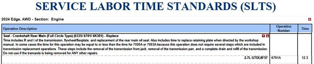
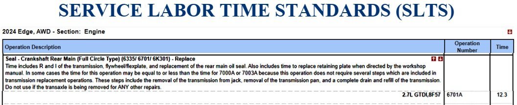
SSM 53292 - 2018-2025 Various Vehicles - 2.7/3.0L EcoBoost - Engine Oil Leak From The Crankshaft Rear Seal With Retaining Plate Some 2018-2024 F-150/Edge, 2018 MKX, 2019-2023 Nautilus, 2020-2025 Explorer/Aviator, 2021-2024 Bronco, and 2024 Ranger vehicles equipped with a 2.7L or a 3.0L EcoBoost engine may exhibit an engine oil leak from the crankshaft rear seal with retaining plate. If diagnostics lead to the replacement of the crankshaft rear seal with retaining plate, the crankshaft rear seal with retaining plate has been updated for improved sealing performance. Replace the crankshaft rear seal with retaining plate with the updated part (JT4Z-6335-C) or latest level part. Refer to the Workshop Manual (WSM), Section 303-01. For claiming, use causal part 6335 and applicable labor operations in Section 06 of the Service Labor Time Standards (SLTS) Manual. The referenced Workshop Manual section is attached below as a PDF document... Crankshaft Rear Seal with Retainer Plate - 2.7L EcoBoost - Removal and Installation - 2022-2024 Edge Workshop Manual.pdf
- 1 reply
-
- 3
-

-
@johnmarkp: From the 2019 Edge Workshop Manual, attached below as PDF documents... Good luck! Hydraulic Control Unit (HCU) - Removal and Installation - 2019 Edge Workshop Manual.pdf Anti-Lock Brake System (ABS) Module - Removal and Installation - 2019 Edge Workshop Manual.pdf
-
GSB 25-7000 - Interior Trim Concern Analysis (For Warrantability)
Haz replied to Haz's topic in Recalls, TSBs & Warranty
GENERAL SERVICE BULLETIN Interior Trim Concern Analysis 25-7000 08 January 2025 This bulletin supersedes 23-7034. Reason for update: update the vehicle model years affected and Service Information Markets: North American markets only Summary Use this document to assist in determining warrantable interior trim and steering wheel conditions. Service Information For fabric, carpets, cloth seats, safety belts, and interior trim: • Re-adhering loose leather to the steering wheel can be completed per the WSM • Do not use cleaning solvents, bleach or dye on the vehicle’s safety belts, as these actions may weaken the belt webbing • Remove dust and loose dirt with a vacuum cleaner • Remove light stains and soil with Motorcraft products as instructed in the vehicle Owner’s Manual • Do not use household cleaning products or glass cleaners, which may damage the finish of the instrument panel, interior trim and cluster lens, and can stain and discolor fabric • Avoid cleaners or polishes that increase the gloss of the upper portion of the instrument panel. The dull finish in this area helps protect you from undesirable windshield reflection • Make sure to wash or wipe hands clean if they have been in contact with certain products such as insect repellent and suntan lotion in order to avoid possible damage to the interior • Do not allow air fresheners and hand sanitizers to spill onto interior surfaces Non-warrantable conditions: • Interior damage • Scratches • Soiling, obvious vandalism or abuse • Pry marks • Damage, burns, soil marks, cuts, scratches, scuffs, tears or punctures • Damage due to chemicals, solvents, or use of non-Ford approved cleaners • Leather/stitching damaged during removal of steering wheel wrap • Leather/vinyl normal deterioration and wear • Wood natural grain pattern variation (such as grain direction, frequency, knots) • Dye transfer from customer clothing • Cracked button/dial surfaces • Stuck buttons/dials/switches due to spilled liquids or other debris Cuts, Scratches, Scuffs, Tears Or Punctures (Non-warrantable) (Figures 1-3) Figure 1 Figure 2 Figure 3 Bubbles (Warrantable) (Figures 4-6) Figure 4 Figure 5 Figure 6 Stains From Chemical Influence (Non-warrantable) (Figures 7-9) Figure 7 Figure 8 Figure 9 Broken Attachments (Non-warrantable) (Figure 10) Figure 10 Alignment, Fit, Warped (Warrantable) (Figures 11-13) Figure 11 Figure 12 - Warped instrument panel (Warrantable) (Figure 12) Figure 13 - Warped glove box door (Warrantable) (Figure 13) Stained Headliner (Non-warrantable) (Figure 14) NOTE: Staining as the result of a defect would be covered as related damage. Figure 14 Rough Cut Headliner, Normal Appearance (Non-warrantable) (Figure 15) Figure 15 Creased Headliner (Non-warrantable) (Figure 16) Figure 16 Headliner Edge Visible (Warrantable) (Figure 17) NOTE: Complete removal/installation may be required to ensure proper alignment. Figure 17 Loose Mat Anchor (Warrantable) (Figure 18) NOTE: With no associated liquid staining present. Figure 18 Loose Carpet (Warrantable) (Figure 19) NOTE: Compete removal/installation may be required to establish a proper fit. Figure 19 Stains (Non-warrantable) (Figure 20) NOTE: Abrasive liquid may dissolve carpet fibers. Figure 20 Carpet Matted Appearance (Warrantable) (Figure 21) NOTE: This appearance may be the result of depressed fibers. This can be corrected by cleaning and reanimating the fibers using a carpet/steam cleaner (with temperatures under 350 degrees Fahrenheit) in the area. If a carpet/steam cleaner is not available, this procedure can be sublet out to a local interior/detail shop. If a shop is not locally available, a steamer such as Rowenta steamer or equivalent can be purchased and used to correct this condition. This tool purchase should be claimed as an outside service part (OSP). Figure 21 Carpet Cut (Non-warrantable) (Figure 22) Figure 22 Carpet Edges Fraying (Non-warrantable) (Figures 23-24) NOTE: Carpet edges are typically unfinished and fraying may be a normal characteristic. Examples of this may include, but are not limited to, front/rear/side edges, overlapped edges, and cutouts. These can be improved by trimming with scissors to remove loose fibers. It is not necessary to replace the carpet for this condition. Figure 23 Figure 24 Carpet Pile Appearance (Non-warrantable) (Figures 25-26) Figure 25 - Frayed appearance can be corrected by mild brushing of the pile in a forward direction. This would be considered part of vehicle care and not eligible for warranty. Figure 26 - Frayed appearance on left side of image can be corrected by mild brushing in a forward direction as seen on the right side. Leather Steering Wheel Worn Or Peeling (Warrantable) (Figure 27) Figure 27 Urethane Steering Wheel Worn Or Peeling (Warrantable) (Figure 28) Figure 28 Steering Wheel Abrasion (Non-warrantable) (Figure 29) Figure 29 Urethane Steering Wheel Mold Marks (Non-warrantable) (Figure 30) Figure 30 Leather Steering Wheel Loose Thread, Originates At The Knotted End Of The Thread (Warrantable) (Figure 31) Figure 31 Leather Steering Wheel Cut Thread (Non-warrantable) (Figure 32) Figure 32 Steering Wheel Modification (Non-warrantable) (Figure 33) Figure 33 Steering Wheel Cover Repair (Warrantable) (Figure 34) Can be repaired per the Workshop Manual. Figure 34 Sticking Knobs And Switches (Non-warrantable) (Figures 35-36) Interior control assemblies returned with sticking knobs and switches from contamination are subject to warranty review and adjustment. Figure 35 Figure 36 © 2025 Ford Motor Company All rights reserved. NOTE: This information is not intended to replace or supersede any warranty, parts and service policy, workshop manual (WSM) procedures or technical training or wiring diagram information.- 1 reply
-
- 1
-
-
Take it from the OG (a general term to praise someone who is an expert at something)... Good luck!
-
Recapping passages from the previously posted Power Liftgate System Operation and Component Description... While the power liftgate is opening, the RGTM monitors the liftgate motor position sensor for liftgate position and velocity. (The RGTM monitors & controls the Liftgate Motor) When the power liftgate reaches the full open position, the RGTM removes the power from the drive motor. (The RGTM knows the default Full Open Position for the Liftgate Motor) The power liftgate open height can be programmed to open to a height other than the full open position. (The RGTM's powering off of the Liftgate Motor can be changed to less-than Full Open Position) The programmed power liftgate height is retained when the battery is disconnected. (Simply removing power from the RGTM does not remove the less-than Full Open Position setting) And from Power Liftgate Initialization... Remove the battery power from the RGTM for 20 seconds before entering initialization mode. Wait 20 seconds and reconnect the battery or reinstall the RGTM fuse(s). If the liftgate is not already in the fully closed position, manually close and fully latch the power liftgate. Power open the liftgate by using a programmed RKE transmitter or the front control switch. Once the liftgate is fully open, power close the liftgate by using a programmed RKE transmitter or the front power liftgate control switch. (The 20-second RGTM power removal and the subsequent power opening cycle of the Liftgate Motor re-enables default Full Open Position setting) Since your repeated attempts to restore the RGTM to its default Full Open Position haven't been successful, I expect a Software Fault other-than something that would set a Diagnostic Trouble Code (DTC) exists. Regardless of the version of Forscan you have, you can at least compare the RGTM's currently programmed values to your Edge's VIN-based historical RGTM As-Built data, however, I suspect the RGTM's default Full Open Position setting exists in the Module's firmware, rather than in the programmable As-Built data. Back in March 2012, Ford issued TSB 12-3-9 (Direct PDF download link) to remedy a Liftgate bounce back issue affecting 2012 Edge-MKX built before 11/28/2011, including our 2012 MKX that sporadically exhibited the problem. The fix was a RGTM software update that modified the downward velocity of the Liftgate Motor's power closing cycle, which restored consistent latching outcomes. Given that such Liftgate Motor performance parameters are controlled by the RGTM and positive outcomes were restored by TSB 12-3-9's software update, I expect it may take a re-flashing of your Edge's RGTM firmware, which the 2017 Edge Workshop Manual says is possible... ...to re-establish the Module's 'lost knowledge' of the Liftgate Motor's Full Open Position. But, it wouldn't hurt to look at the RGTM's Line 775 programmed values to see if they match your Edge's VIN-based historical As-Built data -- and if you find differences, your dealer may be able to answer the "As-Built data versus Module Re-Flashing" question to restore the RGTM's awareness of Full Open Position -- if your Forscan setup cannot affect change to the Module's Line 775 programmed values. Good luck!


-
SSM 53289 - 2024-2025 Nautilus, 2025 Explorer/Aviator - Person In The Vehicle Cannot Be Heard During Inbound Call Some 2024-2025 Nautilus and 2025 Explorer/Aviator vehicles may exhibit a concern where during an inbound phone call the person in the vehicle cannot be heard. This may be due to the software in the accessory protocol interface module (APIM). Replacement or reprogramming of the APIM will not resolve this condition. Inform customers that Ford is working on additional software enhancements which are expected to be delivered over-the-air (OTA) by late Q1 2025. Software will update automatically if vehicle connectivity is enabled in the vehicle's settings. Schedule a service visit for customers who have disabled vehicle connectivity or who report that they did not receive the update in late Q1 2025. Monitor Professional Technician System (PTS) for additional information.
-
Welcome to the Forum @ArtdW! Two suggestions from the 2013 Edge Workshop Manual's Engine Noise Vibration Harshness (NV) Symptoms Chart... Engine and transaxle mount images from 2013 Edge Workshop Manual... Remove the transaxle support insulator through bolt and nut. Remove the 3 nuts, the bolt and the transaxle support insulator bracket. Remove the nut, bolt and engine mount brace. Remove the 4 engine mount nuts. Flexplate Inspection procedure from the 2013 Edge Workshop Manual, and Technical instructions from a 2015-2018 2.0L EcoBoost Flexplate cracks inspection Customer Satisfaction Program are attached below as PDF documents... While the Customer Satisfaction Program does not apply to your Edge, due to its model year and its 3.5L Duratec, the technical instructions' imagery and inspection method description may be helpful. Based upon the symptom in the video, and your impression that the noise is coming from the back of the engine, you may want to use a borescope to inspect the Flexplate for cracks. Good luck! Flexplate Inspection - General Procedures - 2013 Edge Workshop Manual.pdf Customer Satisfaction Program 22N12 - 2015-2018 MY 2.0L EcoBoost - Flexplate Inspection Technical Instructions.pdf


-
Special Service Message 51117 - Effective October 4, 2022... SSM 51117 - 2019-2022 Various Vehicles - Illuminated All Wheel Drive (AWD) Warning Indicator Or Fault Message With Certain DTCs Some 2021-2022 Bronco Sport 1.5L, 2019-2022 Edge/Nautilus, 2020-2022 Escape/Corsair, and 2022 Maverick vehicles may exhibit an illuminated AWD warning indicator or fault message with diagnostic trouble code (DTC) C0095:71/:19 stored in the all wheel drive (AWD) module. Some 2021-2022 Bronco Sport 2.0L may exhibit an illuminated AWD warning indicator or fault message with DTC C05D9:71, C05E8:71, C05D8:19 and/or C05E7:19 stored in the AWD module. This may be due to a rear drive unit (RDU) motor magnet ring misalignment. RDU assembly replacement is no longer required. To correct the condition, replace the RDU motor which is now available separately for service. Refer to Workshop Manual, Section 205-02 for diagnosis and repair procedures. For claiming use causal part 4C210 and applicable labor operations in Section 10 of the Service Labor Time Standards (SLTS) Manual. Good luck!
-
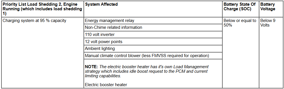
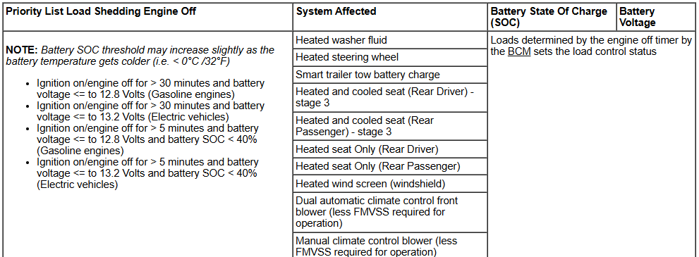
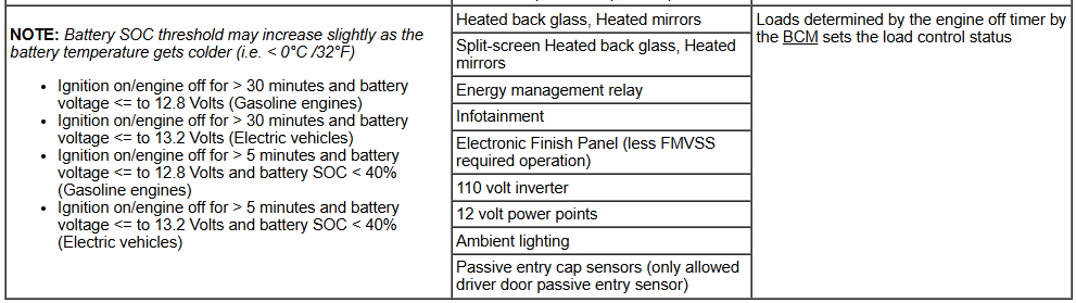
From the 2019 Edge Workshop Manual... Placing your device cursor over underlined acronyms may yield popup full-words descriptions of the acronyms. Battery Load Shed The main purpose of controlling electrical consumption with a load management strategy is to: Limit battery discharge Monitor the battery charge status The alternator is not dimensioned to support all loads in all situations. In some situations energy has to be drawn from the battery. These are mainly during: engine idle cold climate with a lot of electrical heating functions active warm conditions with the engine cooling fan running large transient loads (i.e. EPAS ) During cold conditions, the charge acceptance of the battery is very low which increases the time needed to recharge the battery. This means that it can take up to several hours of driving before the battery is recharged. The electrical consumption control is using Ignition_Status, Remote_Start_Status and EngineStateInternal in order to define the load management strategy during the different operating states of the vehicle. The BCM is the primary module that is responsible for controlling the load management strategy. The BCM processes measurements of the system and uses the information for calculations and load prioritization The strategy allows drain to occur from the battery. Load Management minimizes the drain by controlling the time and magnitude of the drain that can occur. The battery drain changes depending on the driving cycle and the types of loads the driver has activated, therefore, the BCM must be able to shut down or reduce the loads if necessary. The intent of the initial load shed stage, LSHED1, is to reduce electrical loads in a manner that is not noticed by the vehicle operator. During LSHED1, requests are sent in a prioritized order for the appropriate modules to begin shedding available loads. In order to prevent customer satisfaction issues, the loads are requested to reduce power consumption with minimum impact to the customer. The second load shed event, LSHED2, occurs in two stages, SHED2_TRANS and SHED2_CONTIN. During operation of a vehicle equipped with large transient loads, there are transient peaks for current draw. The Load Management algorithm reacts to these spikes by using the SHED2_TRANS state. This state requires all non-critical loads to shed immediately, without customer indication, so that large transient loads can operate normally with little to no adverse impact to the customer. SHED2_CONTIN is a continuous deactivation of the loads to ensure the vehicle is able to re-start once the ignition is turned off. During SHED2_CONTIN, a message is displayed to the vehicle operator notifying them of the vehicle's charging system status. Independent of load shed requests, the Load Management control can request boosts to the engine idle speed. Boosting the engine idle speed allows for increased output of the alternator to deliver more current to the battery. Idle speed increases are done through network IBoost messages. The load shed charts provide a general overview of the features available on the vehicle based on the build options. Load Shed Charts Priority List Load Shedding 1 Priority List Load Shedding 2 Priority List Load Shedding Engine Off Good luck! Battery Load Shed - Description and Operation - 2019 Edge Workshop Manual.pdf

-
I was similarly curious, especially given the same document's inclusion in the 2021 Edge Workshop Manual, with the same Procedure Revision Date of October 22, 2024. It's likely an editorial oversight, since lacking side view cameras, it seems only a historical strip of peripheral front camera images would be available for stitching into a time-lapsed view of what has been on either side of the vehicle, rather than a live view of what presently exists. Good luck!
-
If your Edge is not equipped with Automatic Headlamp Leveling... The mid and high series headlamps may be equipped with automatic headlamp leveling. The headlamp beam height is automatically adjusted according to vehicle load, speed, acceleration and braking. Automatic headlamp leveling is activated when the headlamp switch is in the HEADLAMPS or AUTOLAMPS position. ...then it may be Connector C2129 for the Headlamp Control Module (HCM), which is only installed on vehicles equipped with automatic headlamp leveling... Good luck! Headlamp Control Module (HCM) - Connector C2129 Pinout - 2021 Edge.pdf
-Illustration-2021EdgeWorkshopManual.thumb.jpg.4b22832496db8b28eac4c659fae38a96.jpg)
-ConnectorC2129Location-2021Edge.jpg.afca1d8708ed061b2cc44d9e3895ba77.jpg)
-
From the 2021 Edge Wiring Resource... Good luck! Inline Connector C133 - Circuit ID Pinout - 2021 Edge.pdf Inline Connector C133 - Location - 2021 Edge.pdf Inline Connector C139 - Circuit ID Pinout - 2021 Edge.pdf Inline Connector C139 - Location - 2021 Edge.pdf Inline Connector C212 - Circuit ID Pinout - 2021 Edge.pdf Inline Connector C212 - Location - 2021 Edge.pdf Inline Connector C213 - Circuit ID Pinout - 2021 Edge.pdf Inline Connector C213 - Location - 2021 Edge.pdf Inline Connector C408 - Circuit ID Pinout - 2021 Edge.pdf Inline Connector C408 - Location - 2021 Edge.pdf Inline Connector C411 - Circuit ID Pinout - 2021 Edge.pdf Inline Connector C411 - Location View #1 - 2021 Edge.pdf Inline Connector C411 - Location View #2 - 2021 Edge.pdf
-
Help - Code: C1039:94-0A Active Front Steering (AFS) Lock
Haz replied to al303's topic in Brakes, Chassis & Suspension
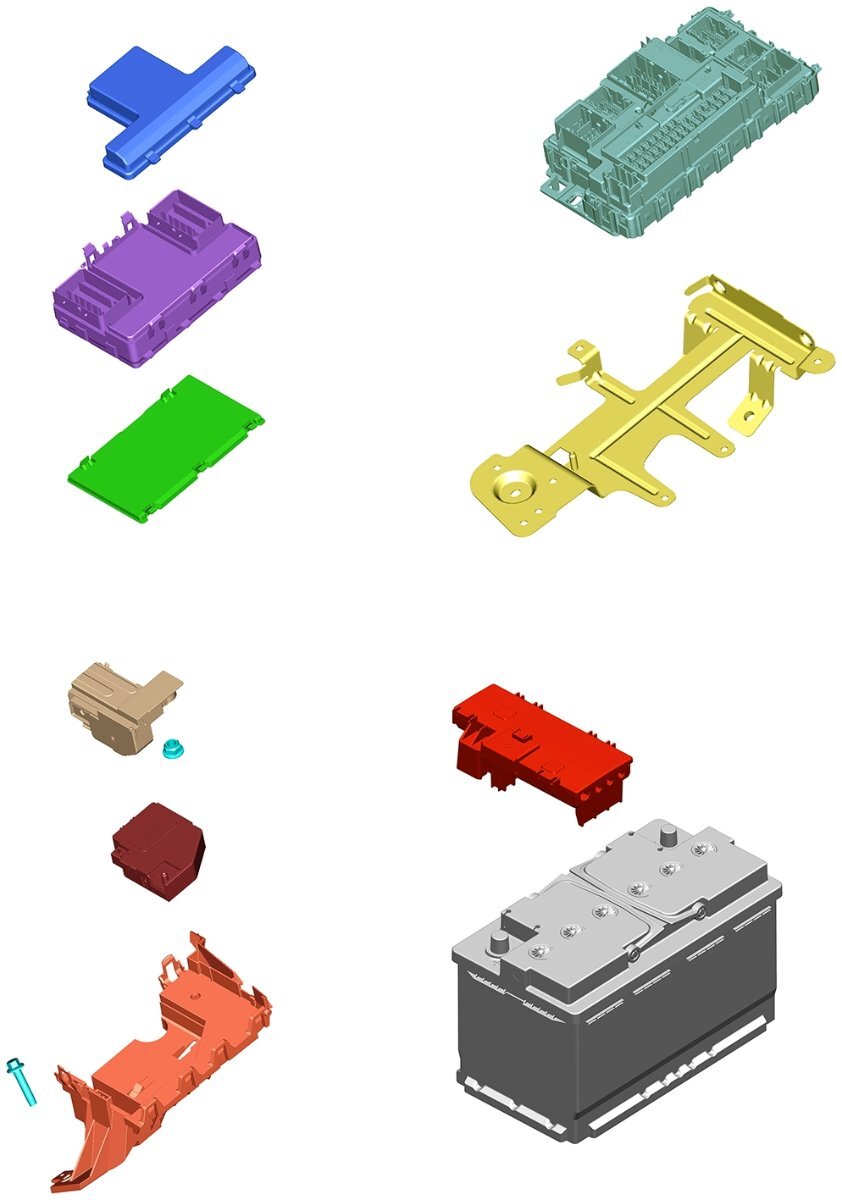
Adding High Current Battery Junction Box (BJB) information... This BJB exploded view illustration might be useful toward locating: Good luck! High Current Battery Junction Box (BJB) - Illustration - 2018 Edge.pdf High Current Battery Junction Box (BJB) - Location View #1 - 2018 Edge.pdf High Current Battery Junction Box (BJB) - Location View #2 - 2018 Edge.pdf High Current Battery Junction Box (BJB) - Wiring Diagram - 2018 Edge.pdf High Current Battery Junction Box (BJB) - Connector C1617G [to F1 (40 Amp)] Detail - 2018 Edge.pdf BJB Exploded View Illustration - FordParts_com.pdf
-
Help - Code: C1039:94-0A Active Front Steering (AFS) Lock
Haz replied to al303's topic in Brakes, Chassis & Suspension
@al303: To emphasize the importance of your Health and Safety awareness, the SRS Depowering and SRS Repowering procedures are included here and are also provided below as PDF documents, as is a general Pyrotechnic Device Health and Safety Precautions document... Work safely! Supplemental Restraint System (SRS) Depowering - General Procedures - 2018 Edge Workshop Manual.pdf Driver Airbag - Vehicles With Adaptive Steering - Removal and Installation - 2018 Edge Workshop Manual.pdf Pyrotechnic Device Health and Safety Precautions - General Procedures - 2018 Edge Workshop Manual.pdf Battery Disconnect and Connect - General Procedures - 2018 Edge Workshop Manual.pdf Supplemental Restraint System (SRS) Repowering - General Procedures - 2018 Edge Workshop Manual.pdf Adaptive Steering - SECM Wiring Diagram - 2018 Edge.pdf STEERING EFFORT CONTROL MODULE (SECM) - Connectors C2391A, C2391B, C2391C Location - 2018 Edge.pdf STEERING EFFORT CONTROL MODULE (SECM) - Connectors C2391A Pinout - 2018 Edge.pdf STEERING EFFORT CONTROL MODULE (SECM) - Connectors C2391B Pinout - 2018 Edge.pdf STEERING EFFORT CONTROL MODULE (SECM) - Connectors C2391C Pinout - 2018 Edge.pdf CLOCKSPRING-STEERING ANGLE SENSOR MODULE (SASM) - Connector Locations - 2018 Edge.pdf STEERING EFFORT CONTROL MODULE (SECM) - Ground G200 Location - View #1 - 2018 Edge.pdf STEERING EFFORT CONTROL MODULE (SECM) - Ground G200 Location - View #2 - 2018 Edge.pdf Steering Column Shrouds - Removal and Installation - 2018 Edge Workshop Manual.pdfDepowering-GeneralProcedures-2018EdgeWorkshopManual.thumb.jpg.a88cf6661fc06b9cf96b7543efde2681.jpg)
Repowering-GeneralProcedures-2018EdgeWorkshopManual.thumb.jpg.b60bd7d8858304d84fd413e40d64e3be.jpg)
-
Welcome to the Forum,@longbeachbob! No modifying Supplement to Emission Recall 24E10 has been posted to Ford's Professional Technician System (PTS) website, thus far. If the affected vehicle population was being modified, a Supplement would be issued and/or if a pause in the Field Service Action was occurring, a notification would be posted to PTS. If either of these announcements are made, I will post them here and to the original announcement. Congrats on your Edge's successful smog test. Was it a Basic Test with OBDII connection and tailpipe probe, or does your location require the Enhanced Test that included your Edge running on a dyno during sampling? Good luck!
-
With emphasis added... SSM 53280 - 2024 Nautilus - Driver Seat And Steering Column Not Moving To Easy Entry Position After Setting Up A Client Profile Some 2024 Nautilus vehicles may exhibit a concern with the driver seat and steering column moving to the saved memory position instead of the easy entry position when approaching or unlocking the vehicle with the key fob. This condition may occur after setting up a client profile and is due to the driver front seat module (DSM) software. Inform customers that they can continue to drive the vehicle and that engineering is currently working on revised DSM software for this condition that is expected Q1 2025. In the interim, easy entry will function if the key fob is unlinked from the customers personal profile by selecting the profile on the center display screen, pressing the edit icon, choosing ID Method, pressing Unlink Key Fob, and then selecting Unlink from the pop-up screen. The customers driver seat and steering column memory settings will no longer be saved to the key fob but can be recalled by using the memory switches on the door or on the center display screen. Monitor PTS for additional information and schedule service appointments for customers once the repair becomes available. This Special Service Message 53280 has also been posted on Ford's Canadian Professional Technician System (PTS) website.

-FuseF23Red-Boxed-2016Edge.jpg.cdc255582157973b2576e6b6afc47d7d.jpg)

-Illustration-2021EdgeWorkshopManual.jpg.e75b7c476e0ead894a367303618f8da4.jpg)
Depowering-GeneralProcedures-2018EdgeWorkshopManual.jpg.d1b088ec24b713439faa49f4ac742623.jpg)
Repowering-GeneralProcedures-2018EdgeWorkshopManual.jpg.f6f24d3797cf8b72aaba62dbcceb185c.jpg)