Haz
-
Posts
1,568 -
Joined
-
Last visited
-
Days Won
439
Content Type
Profiles
Forums
Gallery
Everything posted by Haz
-
Edge 2.7 EcoBoost specification from the 2016 Workshop Manual... Oil Pressure NOTE: The following oil pressure readings are acquired using a scan tool and monitoring the EOP_PRESS PID. Item Specification Reading 1: Minimum average oil pressure @ 2,000 rpm after 15 secs with engine at normal operating temperature and transmission in Park 21 psi (144.8 kPa) Reading 2: Minimum average oil pressure @ 2,000 rpm after 15 secs with engine at normal operating temperature and transmission in Park (Oil Pressure Control Solenoid connector disconnected) Reading 1 value plus 8 psi (55.1 kPa) Good luck!
-
2007 Ford Edge hvac, actuator, heater core Desperate
Haz replied to Ekim's topic in Interior, A.C., Heat, Interior Trim
No insights on the Blend Door(s) and operating shaft are provided in the Workshop Manual, unfortunately, though YouTube includes video of a Ford truck owner cutting a portion of its climate control housing to access a blend door needing repair, as an alternative to removing the entire housing from behind the dash. @WWWPerfA_ZN0W's recent advice on performing an actuator reset is worth a try. Document download links> Heater Core And Evaporator Core Housing - Removal and Installation - 2008 Edge Workshop Manual.pdf Heater Core - Removal and Installation - 2008 Edge Workshop Manual.pdf Temperature Blend Door Actuator - RH, Dual-Zone EATC - Removal and Installation - 2008 Edge Workshop Manual.pdf Good luck! -
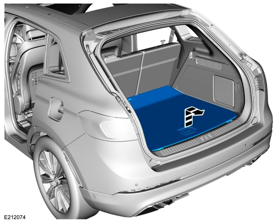
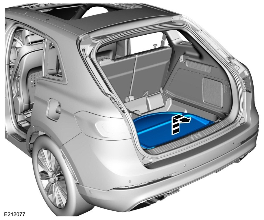
Have you tried removing the panel(s) you describe and taking a test drive, in order to confirm or eliminate it as the source of the noise/vibration/harshness? From the 2016 Edge Workshop Manual... Remove the load compartment floor cover. If equipped: Remove the spare tire cover. Good luck!


-
SSM 52127 2024 Nautilus - Infotainment - Switching From Transport To Normal Mode - No AM, FM Audio Playback And/Or Black Center Display Screen And Right Side Infotainment Display Some 2024 Nautilus vehicles may exhibit no audio playback from the AM, FM radio stations and/or a black center display screen and right side infotainment display when the vehicle is transitioned from transport to normal mode. When the audio volume control knob is rotated, the center display screen may or may not show visual change with no change in audio volume. To correct the condition, perform a manual SYNC module (APIM) reset. Press and hold the audio volume control knob (located on top of the center console) for 10-seconds and release the button - appearance of the welcome animation is an indication that the audio system is resetting. This condition does not affect vehicle durability and no additional diagnosis or service is required for this condition at this time. Make sure the issue is resolved before releasing the vehicle to the customer. SSM 52126 2024 Nautilus FHEV - DTC U053B:86 Setting In The SOBDMC When A Diagnostic Self-Test Is Performed Some 2024 Nautilus full hybrid electric vehicles (FHEV) may set a diagnostic trouble code (DTC) U053B:86 in the secondary on-board diagnostic control module C (SOBDMC) when a diagnostic self-test is performed. This may be due to a communication error between the image processing module A (IPMA) and SOBDMC. Replacement or reprogramming of the IPMA and/or SOBDMC will not resolve this condition. U053B:86 should be ignored and no further service action is required if no other DTCs are present in the IPMA and/or SOBDMC, the IPMA is configured correctly, no warning indicators are illuminated while the engine is running, and no symptoms present. SSM 52125 2024 Nautilus - DTC U3000:49 Setting In The CMR When A Diagnostic Self-Test Is Performed Some 2024 Nautilus vehicles may exhibit diagnostic trouble code (DTC) U3000:49 in the camera module-rear (CMR) when a diagnostic self-test is performed. This may be due to the system triggering a shared variable and then enters a timeout reset process. The history state DTC U3000:49 has no effect on functionality. Replacement or reprogramming of the CMR will not resolve this condition. Engineering is currently working on a solution and a software update is expected in Q2 2024. Continue to monitor OASIS for additional information. SSM 52124 2024 Nautilus - DTC B1578:89 Setting In The IPMA When A Diagnostic Self-Test Is Performed Some 2024 Nautilus vehicles may exhibit diagnostic trouble code (DTC) B1578:89 in the image processing module A (IPMA) when a diagnostic self-test is performed. This may be due to an internal module chip reboot that will recover by itself. B1578:89 has no effect on functionality. Replacement or reprogramming of the IPMA will not resolve this condition. Engineering is currently working on a solution and a software update is expected in Q2 2024. Continue to monitor OASIS for additional information. SSM 52120 2024 Nautilus - DTC U0422:00 Setting In The AWD Module When A Diagnostic Self-Test Is Performed Some 2024 Nautilus vehicles may set diagnostic trouble code (DTC) U0422:00 in the all-wheel drive (AWD) module when a diagnostic self-test is performed. This may be due to a communication error between the body control module (BCM) and AWD module. Replacement or reprogramming of the BCM and/or AWD module will not resolve this condition. U0422:00 should be ignored and no further service action is required if no other DTCs are present in the BCM and/or AWD module, the BCM is configured correctly, no warning indicators are illuminated while the engine is running, and no symptoms present. SSM 52119 2024 Nautilus - DTC U211B:87 Setting In The RFA Module When A Diagnostic Self-Test Is Performed Some 2024 Nautilus vehicles may set diagnostic trouble code (DTC) U211B:87 in the remote function actuator (RFA) module when a diagnostic self-test is performed. This may be due to an internal counter reaching a specified limit. U211B:87 has no effect on functionality and will automatically become a historical DTC which can be cleared. Replacement or reprogramming of the RFA module will not resolve this condition. U211B:87 should be ignored and no further service action is required if no other DTCs are present in the RFA, no warning indicators are illuminated while the engine is running, and no symptoms present. SSM 52118 2024 Nautilus - DTC U211B:87 Setting In The ABS Module When A Diagnostic Self-Test Is Performed Some 2024 Nautilus vehicles may exhibit diagnostic trouble code (DTC) U211B:87 in the anti-lock brake system (ABS) module when a diagnostic self-test is performed. This may be due to a module communication error within a specified timeframe. U211B:87 has no effect on functionality and will automatically become a historical DTC which can be cleared. Replacement or reprogramming of the ABS module will not resolve this condition. Engineering is currently working on a software update which is expected in Q1 2024. Continue to monitor OASIS for additional information. SSM 52117 2024 Nautilus - DTC B00DF:4A Setting In The RCM When A Diagnostic Self-Test Is Performed Some 2024 Nautilus vehicles may exhibit diagnostic trouble code (DTC) B00DF:4A in the restraints control module (RCM) when a diagnostic self-test is performed. This may be due to an internal counter reaching a specified timeframe. B00DF:4A has no effect on functionality. Replacement or reprogramming of the RCM will not resolve this condition. Inform customers that engineering is currently working on a solution for this condition and will be released via Ford Power-Up software updates delivered over-the-air (OTA) expected in Q3 2024. Software will update automatically if vehicle connectivity is enabled in the vehicle's settings. Schedule a service visit for customers who have disabled vehicle connectivity or who report that they did not receive the update in Q3 2024. Monitor OASIS for additional information. SSM 52116 2024 Nautilus - DTC B146F:04 Setting In The SCMG And/Or SCMH When A Diagnostic Self-Test Is Performed Some 2024 Nautilus vehicles may set diagnostic trouble code (DTC) B146F:00 in the drivers multi-contour seat module (SCMG) and/or passenger multi-contour seat module (SCMH) when a diagnostic self-test is performed. This may be due to a communication error to the SCMG/SCMH within a specified timeframe. Replacement or reprogramming of the SCMG/SCMH will not resolve this condition. B146F:00 should be ignored and no further service action is required if no other DTCs are present in the SCMG/SCMH, no warning indicators are illuminated while the engine is running, and no symptoms present. SSM 52115 2023 F-Super Duty, 2023-2024 Expedition, 2024 Nautilus - Remote Start - No LED Confirmation From The Key Fob After A Remote Start Request 2023 F-Super Duty, 2023-2024 Expedition and 2024 Nautilus vehicles will exhibit no light emitting diode (LED) confirmation from the key fob indicating that the vehicle has remote started (or not remote started). Factory key fobs with remote start no longer contain a LED feedback indicator. Do not replace the key fob for this condition. This is a normal operating characteristic and no service action is necessary. SSM 52114 2024 Nautilus – DTC U0415:29 Setting In The PSCM When A Diagnostic Self-Test Is Performed Some 2024 Nautilus vehicles may set diagnostic trouble code (DTC) U0415:29 in the power steering control module (PSCM) when a diagnostic self-test is performed. This may be due to PSCM DTC sensitivity during vehicle key on/start-up. Replacement or reprogramming of the PSCM will not resolve this condition. U0415:29 should be ignored and no further service action is required if no other DTCs are present in the PSCM, no warning indicators are illuminated while the engine is running, and no symptoms present. SSM 52112 2023 E-Transit, 2024 Nautilus - Diagnostic Trouble Codes (DTCS) C0095:18 And/Or C05D9:74 Setting In The AWD Module Some 2023 E-Transit and 2024 Nautilus vehicles may exhibit DTCs C0095:18 and/or C05D9:74 setting in the all-wheel drive (AWD) module with a pop-up message in the instrument panel cluster (IPC) stating there is a loss of AWD. The loss of AWD function may continue for the remainder of the key cycle. AWD functionally may be recovered with a key cycle. Replacement or reprogramming of the AWD module will not resolve this condition. This DTC does not affect vehicle durability and no additional diagnosis or service is required for this condition at this time. Inform customers that they can continue to drive the vehicle and engineering is currently working on a solution for this condition that is expected in Q2 2024. Monitor OASIS for additional information and schedule service appointments for customers once the repair becomes available. SSM 52111 2024 Nautilus - DTC U3001:68 Setting In The PSCM When A Diagnostic Self-Test Is Performed Some 2024 Nautilus vehicles may set diagnostic trouble code (DTC) U3001:68 in the power steering control module (PSCM) when a diagnostic self-test is performed. This may be due to an internal counter reaching a specified limit. U3001:68 has no effect on functionality and will automatically become a historical DTC which can be cleared. Replacement or reprogramming of the PSCM module will not resolve this condition. Engineering is currently working on a software update which is expected in Q1 2024. Continue to monitor OASIS for additional information. SSM 52110 2024 Nautilus - HVAC - Temperature Settings Inaccurate When Using Voice Commands Some 2024 Nautilus vehicles may exhibit inaccurate temperatures on the center display screen when requesting a temperature change using voice commands. Setting temperature and display can still be accurately increased/decreased by adjusting the touch controls. This may be due to a software interaction between the heating, ventilation and air conditioning (HVAC) module and SYNC module (APIM). Inform customers that engineering is currently working on a solution for this condition and will be released via Ford Power-Up software updates delivered over-the-air (OTA) expected in Q2 2024. Software will update automatically if vehicle connectivity is enabled in the vehicle's settings. Schedule a service visit for customers who have disabled vehicle connectivity or who report that they did not receive the update in Q2 2024. Monitor OASIS for additional information. SSM 52109 2024 Nautilus - DTC U211C:04 Setting In The GWM When A Diagnostic Self-Test Is Performed Some 2024 Nautilus vehicles may set diagnostic trouble code (DTC) U211C:04 in the gateway module A (GWM) when a diagnostic self-test is performed. This may be due to a module communication error within a specified timeframe. DTC U211C:04 has no effect on functionality and will automatically become a historical DTC which can be cleared. Replacement or reprogramming of the GWM will not resolve this condition. Engineering is currently working on a software update which is expected in Q1 2024. Continue to monitor OASIS for additional information. SSM 52108 2024 Nautilus FHEV - DTC B1465:08 And B1466:08 Setting In The BCMB When A Diagnostic Self-Test Is Performed Some 2024 Nautilus full hybrid electric vehicles (FHEV) may exhibit diagnostic trouble code (DTC) B1465:08 and B1466:08 in the body control module B (BCMB) when a diagnostic self-test is performed. This may be due to the ambient lighting node not transmitting feedback information within a specified timeframe. Replacement or reprogramming of the BCMB will not resolve this condition. The history state DTC B1465:08 and B1466:08 should be ignored and no further service action is required if no other DTCs are present in the BCMB, the BCMB is configured correctly, no warning indicators are illuminated while the engine is running, and no symptoms present.
-
2007 Ford Edge hvac, actuator, heater core Desperate
Haz replied to Ekim's topic in Interior, A.C., Heat, Interior Trim
Welcome to the Forum, kecusc ! Document download links> Control Components - Climate Control Systems - Description and Operation - 2008 Edge Workshop Manual.pdf Climate Control - Temperature Blend Door Actuator — LH - Removal and Installation - 2008 Edge Workshop Manual.pdf Temperature Blend Door Actuator — LH - Enhanced Image #1 - 2008 Edge Workshop Manual.pdf Temperature Blend Door Actuator — LH - Enhanced Image #2 - 2008 Edge Workshop Manual.pdf Good luck!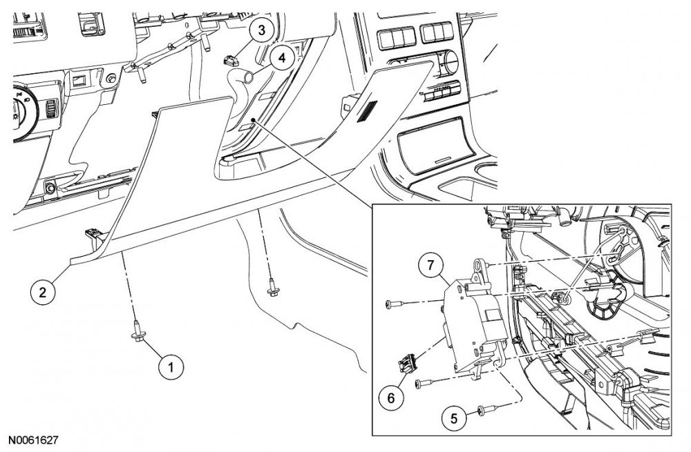

-
Document download link> Image Processing Module B (IPMB) - Removal and Installation - 2016 Edge Workshop Manual.pdf Good luck!
-
2016 Titanium - Low beam not working
Haz replied to Sunil's topic in Glass, Lenses, Lighting, Mirrors, Sunroof (BAMR), Wipers
Since only Low Beams, then it may be worth checking if a nearby national-brand auto parts store is willing to scan your Edge for headlamp-related DTCs, which may show wiring/connector issues versus FET-related BCM replacement need. Good luck! -
2016 Titanium - Low beam not working
Haz replied to Sunil's topic in Glass, Lenses, Lighting, Mirrors, Sunroof (BAMR), Wipers
Welcome to the Forum, Sunil ! From the 2016 Edge Workshop Manual... Low Beams The BCM monitors the headlamp switch position by sending voltage signals on multiple circuits to the headlamp switch. There is one circuit for each headlamp switch position. At any given time, one of the signal circuits is switched to ground to indicate the headlamp switch position. The BCM turns the parking lamps and headlamps on when the ignition is in RUN and the BCM detects a fault from the headlamp switch or wiring. This is normal behavior of the BCM when a fault has been detected with the inputs from the headlamp switch. When the BCM receives a message requesting the headlamps on, it supplies voltage to the headlamp bulbs (halogen headlamps) or the ballasts (High Intensity Discharge (HID) headlamps) within each headlamp assembly. Vehicles with High Intensity Discharge (HID) headlamps utilize a ballast, mounted to each headlamp assembly, to provide the necessary voltage to illuminate the High Intensity Discharge (HID) bulbs. The BCM also provides Field Effect Transistor (FET) protection of the exterior lamps switched voltage and low beam output circuits. When an excessive current draw is detected, the BCM disables the affected circuit driver. Field Effect Transistor (FET) Protection The BCM utilizes an Field Effect Transistor (FET) protective circuit strategy for many of its outputs, for example, lamp output circuits. Output loads (current level) are monitored for excessive current (typically short circuits) and are shut down (turns off the voltage or ground provided by the module) when a fault event is detected. A Field Effect Transistor (FET) is a type of transistor that the control module software uses to control and monitor current flow on module outputs. The Field Effect Transistor (FET) protection strategy prevents module damage in the event of excessive current flow. Output loads (current level) are monitored for excessive current draw (typically short circuits). When a fault event is detected the Field Effect Transistor (FET) turns off and a short circuit DTC sets. The module resets the Field Effect Transistor (FET) protection and allows the circuit to function when the fault is corrected or the ignition state is cycled off and then back on. When the excessive circuit load occurs often enough, the module shuts down the output until a repair procedure is carried out. Each Field Effect Transistor (FET) protected circuit has 3 predefined levels of short circuit tolerance based on a module lifetime level of fault events based upon the durability of the Field Effect Transistor (FET). If the total tolerance level is determined to be 600 fault events, the 3 predefined levels would be 200, 400 and 600 fault events. When each level is reached, the DTC associated with the short circuit sets along with DTC U1000:00. These Diagnostic Trouble Codes (DTCs) can be cleared using the module on-demand self-test, then the Clear DTC operation on the scan tool (if the on-demand test shows the fault corrected). The module never resets the fault event counter to zero and continues to advance the fault event counter as short circuit fault events occur. If the number of short circuit fault events reach the third level, then Diagnostic Trouble Codes (DTCs) U1000:00 and U3000:49 set along with the associated short circuit DTC . DTC U3000:49 cannot be cleared and the module must be replaced after the repair. One Or Both Low Beams is Inoperative DTC Fault Trigger Conditions DTC Description Fault Trigger Conditions B1D00:11 Left Low Beam: Circuit Short To Ground A continuous memory and on-demand DTC that sets when the BCM detects a short to ground from the LH low beam output circuit. B1D00:15 Left Low Beam: Circuit Short To Battery Or Open A continuous memory and on-demand DTC that sets when the BCM detects an open from the LH low beam output circuit. B1D01:11 Right Low Beam: Circuit Short To Ground A continuous memory and on-demand DTC that sets when the BCM detects a short to ground from the RH low beam output circuit. B1D01:15 Right Low Beam: Circuit Short To Battery Or Open A continuous memory and on-demand DTC that sets when the BCM detects an open from the RH low beam output circuit. U1000:00 Solid State Driver Protection Active -Driver Disabled: No Sub Type Information This DTC sets when the BCM has temporarily shut down the output driver. The module has temporarily disabled an output because an excessive current draw exists (such as a short to ground). The BCM cannot enable the output until the cause of the short is corrected, the Diagnostic Trouble Codes (DTCs) have been cleared and a successful self-test is run. For additional information on BCM Field Effect Transistor (FET) protection, REFER to: Module Controlled Functions - System Operation and Component Description (419-10 Multifunction Electronic Modules, Description and Operation). U3000:49 Control Module: Internal Electronic Failure This DTC sets when the BCM has permanently shut down the output driver. The module has permanently disabled an output because an excessive current draw fault (such as a short to ground) has exceeded the limits that the BCM can withstand. CORRECT the cause of the excessive current draw before installing a new BCM . For additional information on BCM Field Effect Transistor (FET) protection, REFER to: Module Controlled Functions - System Operation and Component Description (419-10 Multifunction Electronic Modules, Description and Operation). Possible Sources Fuse Wiring, terminals or connectors Bulb Ballast (High Intensity Discharge (HID) headlamps) Headlamp assembly BCM Visual Inspection and Diagnostic Pre-checks Inspect the headlamp assembly for damage. Inspect BJB fuse 44 (20A). Document download links> Headlamps - Wiring Diagram - 2016 Edge.pdf Battery Junction Box (BJB) - Location Illustration - 2016 Edge.pdf Battery Junction Box (BJB) - Top View - 2016 Edge.pdf Battery Junction Box (BJB) - Top View Legend - 2016 Edge.pdf Battery Junction Box (BJB) - Bottom View - 2016 Edge.pdf Battery Junction Box (BJB) - Bottom View Legend - 2016 Edge.pdf Good luck! -
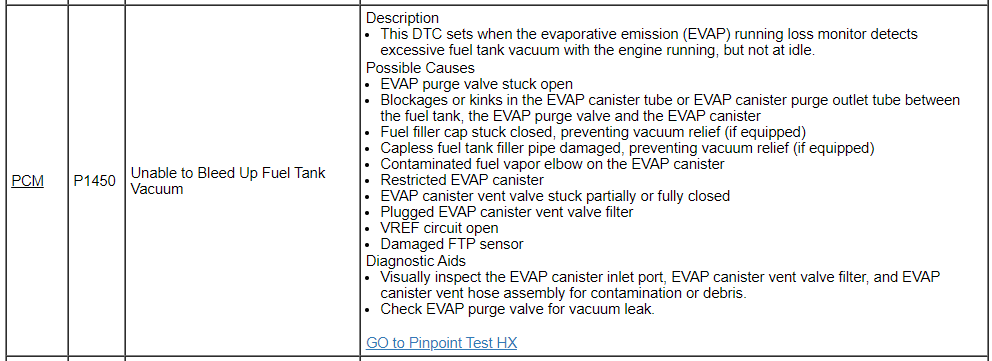
From... Document download links> Evaporative Emission (EVAP) Systems - Description and Operation - 2016 Gasoline - PC-ED Manual.pdf Evaporative Emission (EVAP) Systems - Enlarged System Illustration - 2016 Gasoline - PC-ED Manual.pdf PINPOINT TEST HX - EVAPORATIVE EMISSION (EVAP) SYSTEM AND MONITOR - 2016 Gasoline - PC-ED Manual.pdf EVAPORATIVE EMISSION (EVAP) PURGE VALVE - Connector C1196 Details - 2016 Edge.pdf PINPOINT TEST Z - INTERMITTENT PROBLEMS - 2016 Gasoline - PC-ED Manual.pdf Clear The Continuous Diagnostic Trouble Codes (DTCs) And Reset The Emission Monitors Information In The Powertrain Control Module (PCM) - Diagnostic Methods - 2016 Gasoline - PC-ED Manual.pdf On Board Diagnostic (OBD) Drive Cycle - Diagnostic Methods - 2016 Gasoline - PC-ED Manual.pdf Good luck!
-
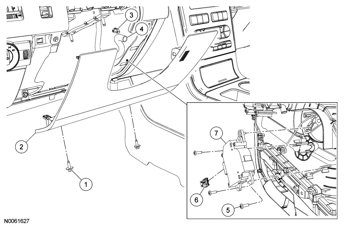
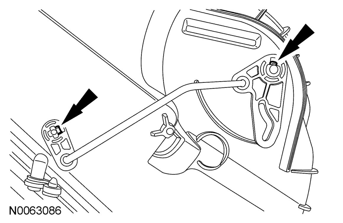
13N02 - Extended Warranty Coverage on Brake Booster
Haz replied to omar302's topic in Recalls, TSBs & Warranty
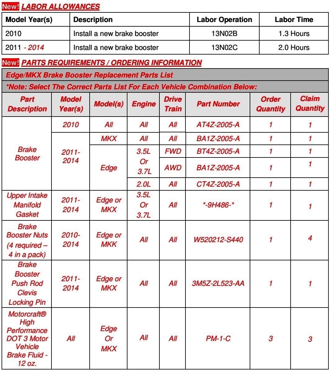
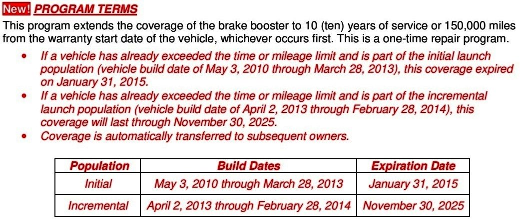
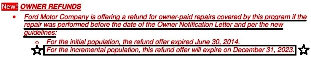
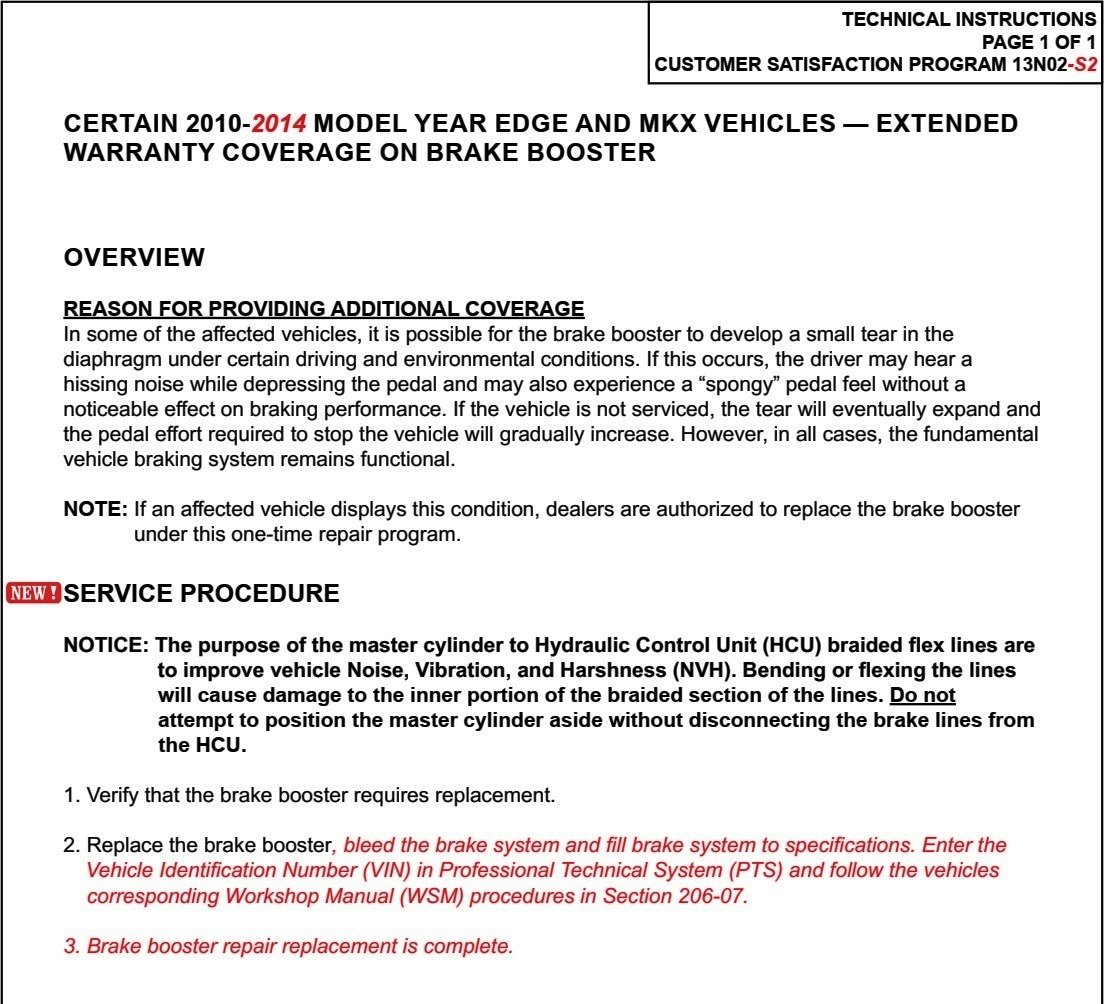
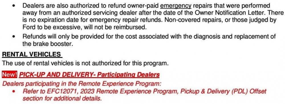
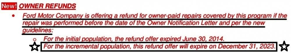
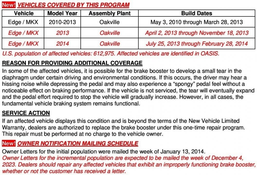
Program 13N02's Brake Booster warranty extension coverage has been incrementally expanded to a larger population of 2013-2014 Edge/MKX vehicles and a Refund program for owner-paid Brake Booster replacements to vehicles in the expanded population is available through December 31, 2023. For full information, see... Customer Satisfaction Program 13N02, Supplement # 2 - Certain 2010-2014 Model Year Edge and MKX Vehicles - Extended Warranty Coverage on Brake Booster (10 Year/150,000 miles) Good luck! -
Supplement #2 Highlights Eligibility expanded to additional 2013 & 2014 Edge/MKX vehicles; Refunds for past owner-paid repairs to expanded vehicle population available through December 31, 2023 expiration date. Document download links to Notification Letter examples being sent to Owners of the incrementally expanded population of Edge & MKX vehicles> Customer Satisfaction Program 13N02 Supplement #2 - Ford Owner Letter - 11-27-2023.pdf Customer Satisfaction Program 13N02 Supplement #2 - Lincoln Owner Letter - 11-27-2023.pdf Link to original Forum post on Field Service Action 13N02 and extensive discussion on Forum member 13N02/Brake Booster experiences


-
denny73: No differences between U.K. and Italy editions of the posted documents. Additional document download link> Rear Drive Axle and Differential - 2.0L EcoBlue - System Operation and Component Description - 2015 - 2022 Edge, Edge Vignale, Endura Workshop Manual.pdf Good luck!
-
The U.K. edition of Ford's Professional Technician System (PTS) website does not show any SSM relating to reprogramming the AWD module, per the above SSM, however it does show TSB 23-2290 covering potential RDU fluid contamination, which was released on the U.K. PTS site before a comparable U.S. SSM 52051, shown in this Forum post that you may also want to look at... Special Service Message 52051 - 2019-2023 Edge/Nautilus + Maverick - AWD - Chatter/Shudder During Low Speed Turning Events U.K Edition document download links> TSB 23-2290 - Chatter-Shudder during low speed turning events - Effective 09-2023.pdf Differential Level Check - General Procedures - 2015 - 2022 Edge, Edge Vignale, Endura Workshop Manual.pdf If you're not the U.K, which EU country represents your Ford vehicle market area? If any differences exist where you reside, I will post further information. Good luck!
-
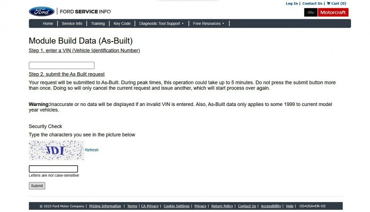
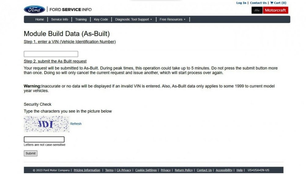
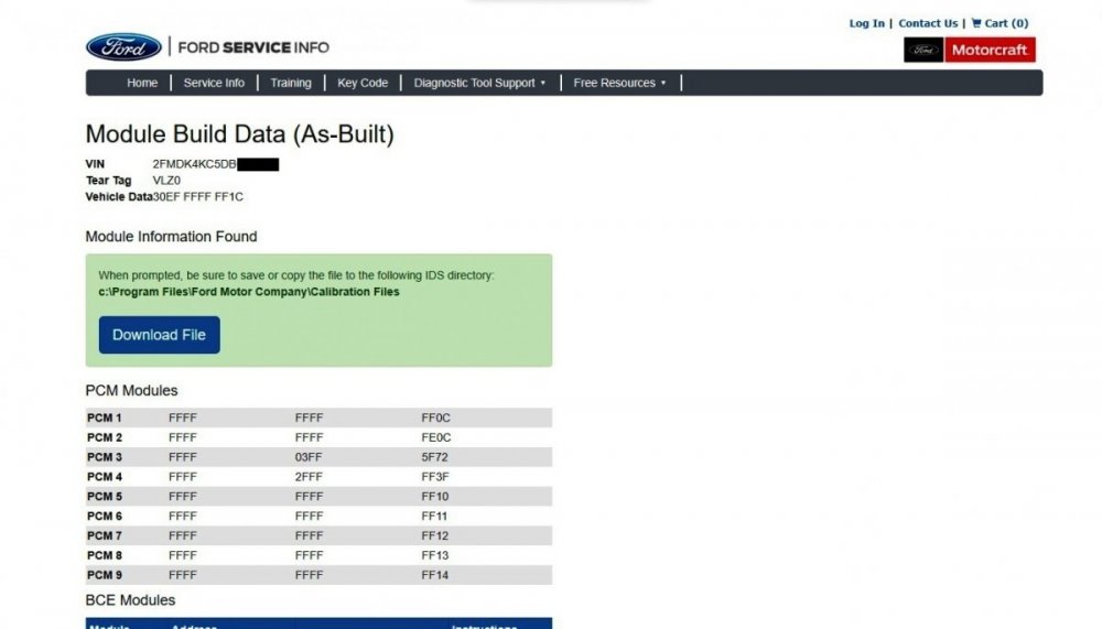
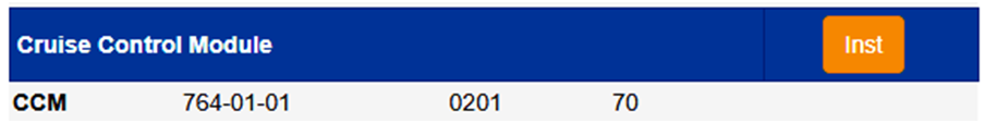
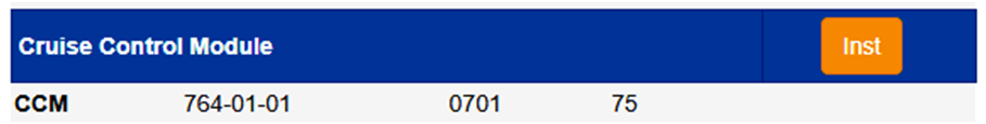
danwdc: You're correct that the Dorman replacement Cruise Control Module (CCM) you installed needs to be programmed with the same As-Built data that was contained in the original CCM you removed. If you did not save those values from the original CCM before removing it, you can use the Ford Service Info website to review and/or save the entire set of As-Built data values for the electronic modules in your 2013 Edge Limited AWD, and then use a temporary-licensed or fully-licensed copy of Forscan to manually program the Dorman replacement CCM using the address 764-01-01 As-Built values and then save them to the installed Dorman replacement CCM. As omar302 advises, go to https://www.motorcraftservice.com/AsBuilt, and after selecting your Country/Language, submit the form... ...input your Edge's VIN and the Security Check captcha value and submit the second form... ...and the resulting As-Built Report for your Edge allows you to Download File an .AB electronic data file that includes the electronic programming for all modules, and the web page provides the same complete data set in text format for you to print for visual reference... I surveyed Cruise Control Module As-Built data for ten 2013 Edge Limited AWD vehicles offered for sale online, and I found two different programming values in use... ...so it is absolutely necessary for you to obtain CCM As -Built data by submitting your Edge's VIN to the Ford Service Info website. Forscan probably shows this Diagnostic Trouble Code (DTC) in the CCM, which you will want to clear if it remains after performing a CCM Self Test after programming the Dorman replacement CCM... U2100:00 Initial Configuration Not Complete: No Sub Type Information Document download link> Module Configuration - Diagnosis and Testing - 2013 Edge Workshop Manual.pdf Good luck!

-
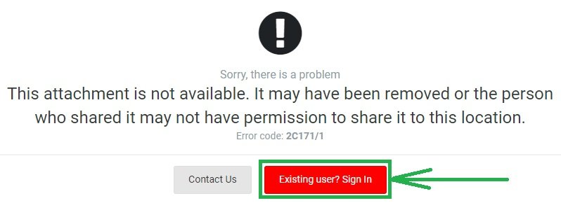
If you are seeing the following message after clicking on a download link, it may be due to you not being signed-in as a Forum member... The above document download links are currently active and, to the best of my knowledge, should be available to any signed-in Forum member. Good luck!
-
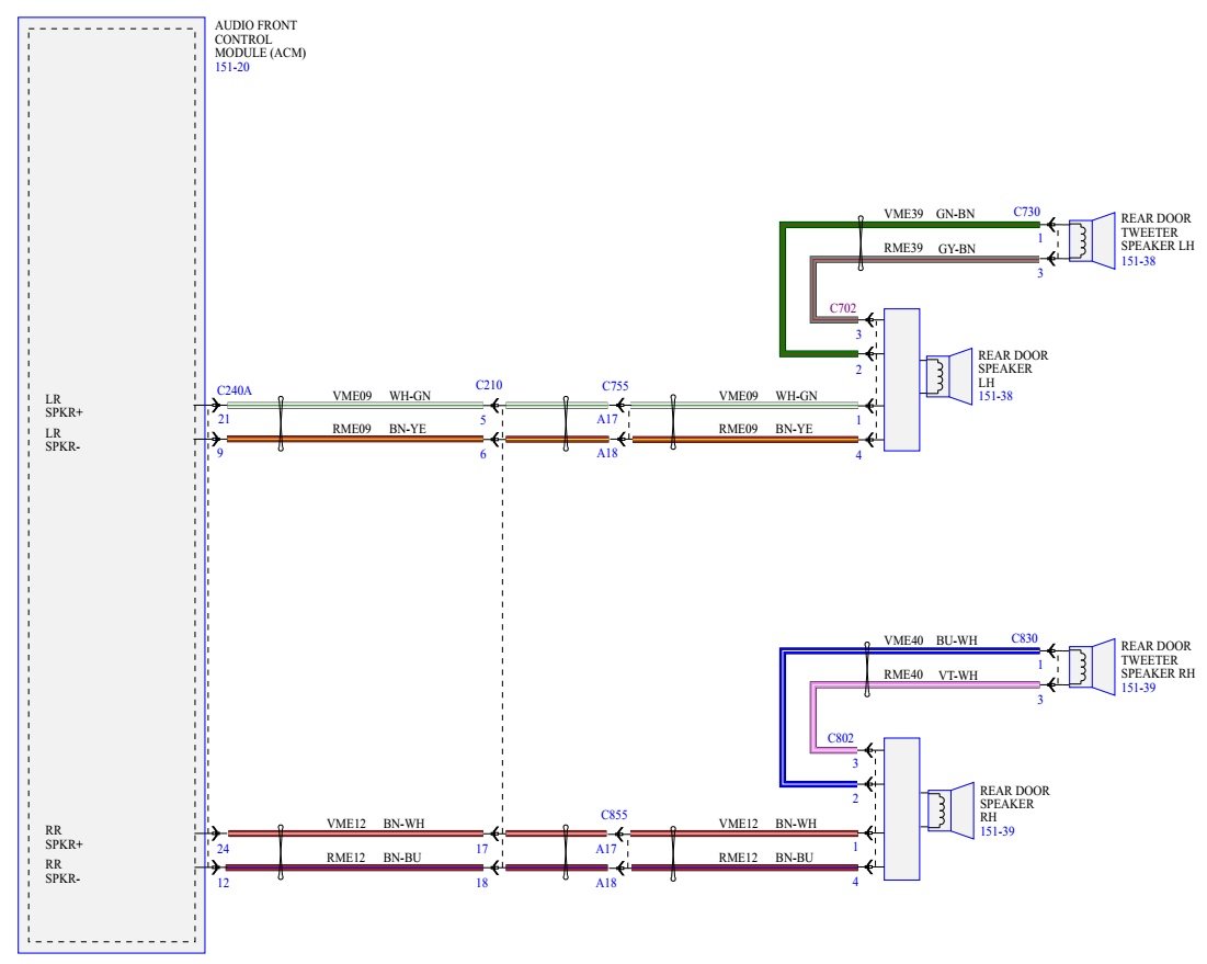
2018 Ford Edge No Rear Tweeter Wire
Haz replied to bhamraS97's topic in Audio, Backup, Navigation & SYNC
Additional document download links> Rear Door Trim Panel - Removal and Installation - 2018 Edge Workshop Manual.pdf Rear Door Window Control Switch - Removal and Installation - 2018 Edge Workshop Manual.pdf Good luck! -
2018 Ford Edge No Rear Tweeter Wire
Haz replied to bhamraS97's topic in Audio, Backup, Navigation & SYNC
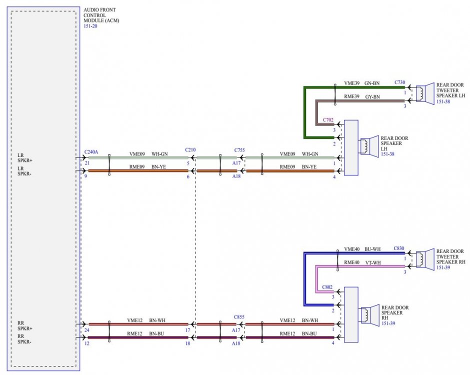
Yes, as the connector details included in your original post show, Pins 1 & 2 convey the positive (+) speaker lead and Pins 3 & 4 convey the negative (-) speaker lead to the door speaker (woofer) and to the door tweeter, loosely illustrated by this photo of the backside of the door speaker from FordParts.com... ...with the paired 1/2 & 3/4 Pins connecting to the door speaker's positive (+) & negative (-) wires off the connector's L-shaped lugs. Good luck!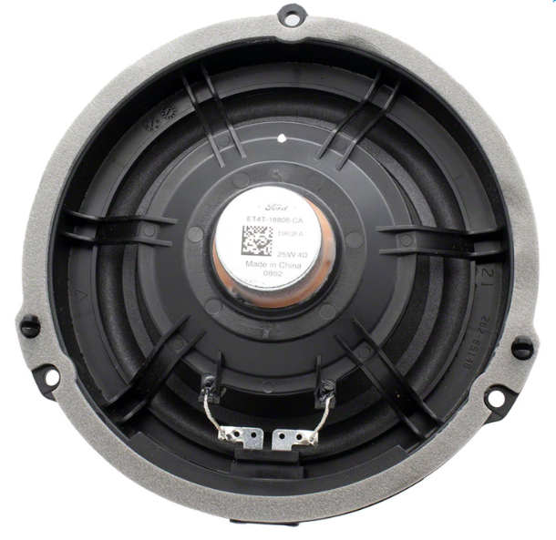
-
2018 Ford Edge No Rear Tweeter Wire
Haz replied to bhamraS97's topic in Audio, Backup, Navigation & SYNC
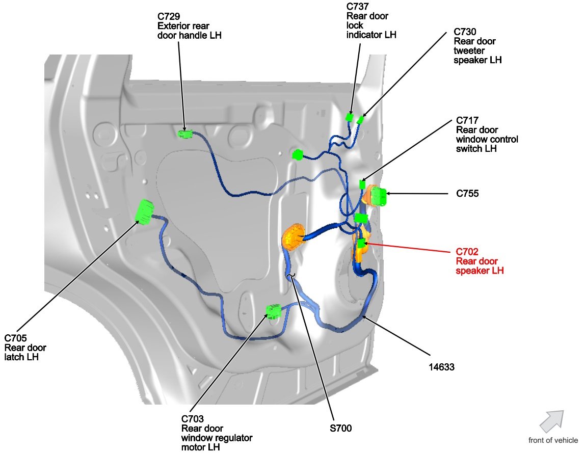
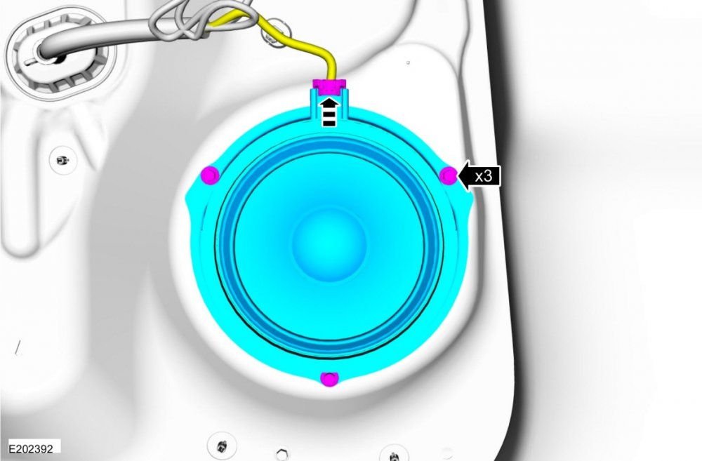
You are both correct... Document download links> Rear Door Speaker Wiring - 2018 Edge.pdf Rear Door Speaker Wiring - Connector Locations - 2018 Edge.pdf Rear Door Speaker LH - Removal and Installation - 2018 Edge Workshop Manual.pdf Rear Door Tweeter Speaker - Removal and Installation - 2018 Edge Workshop Manual.pdf Wiring Diagram Connector Locations Rear Door Speaker Rear Door Tweeter Good luck!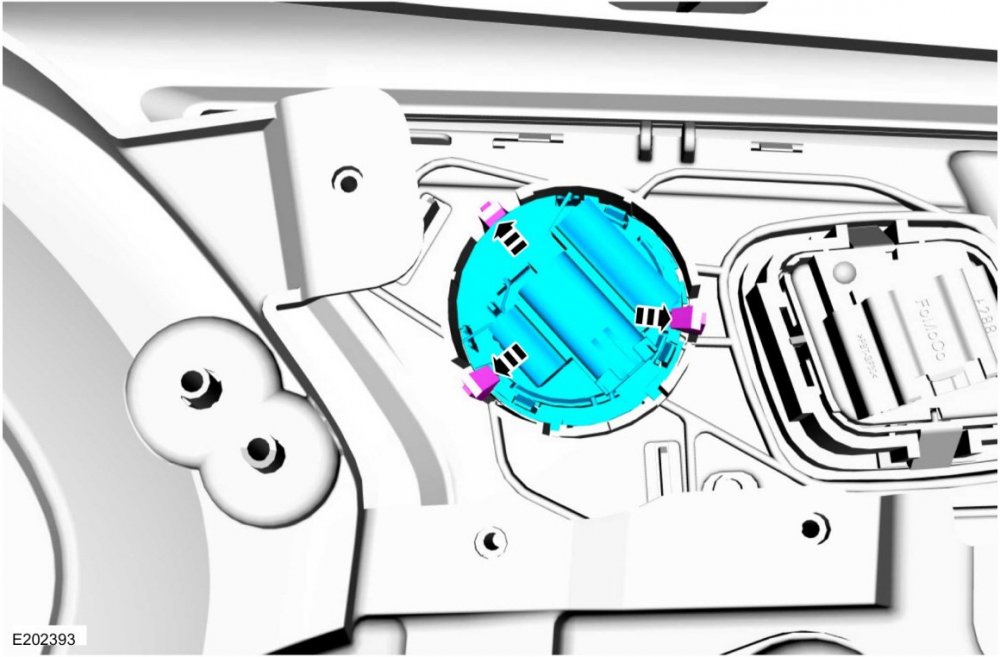

-
Supplemental information on Rear Drive Unit (RDU) operation and the RDU Actuator Motor's appearance and location... Document download links> Rear Drive Axle and Differential - System Operation and Component Description - 2019 Edge Workshop Manual.pdf Rear Drive Unit (RDU) Actuator Motor - Removal and Installation - 2019 Edge Workshop Manual.pdf Good luck!
-
SSM 52076 - 2019-2021 Edge/Nautilus - AWD - RDU Actuator Noise From The Rear Of The Vehicle When Approaching Vehicle Or Prior To Starting Engine Some 2019-2021 Edge/Nautilus vehicles equipped with all wheel drive (AWD) may exhibit a noise from the rear of the vehicle while approaching the vehicle or prior to starting engine. This may be due to the rear drive unit (RDU) actuator learning process. Reprogram the software in the AWD module to minimize the noise using the latest software level of the appropriate Ford diagnostic scan tool. If no other concerns or symptoms are present, further diagnosis or repairs are not recommended. For claiming, use causal part 4000 and applicable labor operations in Section 10 of the Service Labor Time Standards (SLTS) Manual.
-
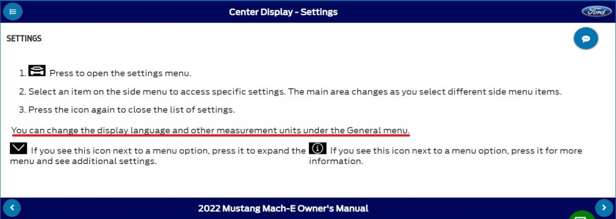
Document download link> TSB 23-2345 - Navigation Feature Unable To Change From Miles To Kilometers On SYNC 4 Equipped Vehicles.pdf TECHNICAL SERVICE BULLETIN Navigation Feature Unable To Change From Miles To Kilometers On SYNC 4 Equipped Vehicles 23-2345 14 November 2023 Model: Ford 2021-2023 Bronco Built on or before 18-Jul-2023 2023 Escape Built on or before 26-Jul-2023 2022-2023 Expedition 2022 Super Duty 2021-2023 F-150 Lincoln 2021-2023 Nautilus Built on or before 03-Apr-2023 2023 Corsair Built on or before 26-Jul-2023 2022-2023 Navigator Issue: Some 2021-2023 Ford and Lincoln vehicles equipped with SYNC 4 may exhibit the navigation feature in the center display screen only displaying imperial (feet and miles) units and not being able to change to metric (meters and kilometers) units. This may be due to the software level of the SYNC module (APIM). To correct this condition, follow the Service Procedure to update the APIM to the latest software level via a coordinated flash. NOTE: The APIM software update that addresses the symptom listed in this article may have been sent via Ford Power-Up software updates delivered over-the-air (OTA) to connected vehicles that have automatic updates enabled through the center display screen. Enter the vehicle identification number (VIN) in Professional Technician System (PTS) and check the OTA Dashboard under the Connected Vehicle tab for OTA update history. If an update to the APIM has successfully completed recently and the customer is reporting the symptoms are no longer present, this article may not apply. Action: Follow the Service Procedure to correct the condition on vehicles that meet all of the following criteria: • One of the following vehicles: - 2021-2023 Bronco built on or before 18-Jul-2023 - 2021-2023 Nautilus built on or before 03-Apr-2023 - 2023 Escape/Corsair built on or before 26-Jul-2023 - 2022-2023 Expedition/Navigator - 2022 F-Super Duty - 2021-2023 F-150 (non-Lightning) vehicles • Equipped with SYNC 4 • Navigation feature in the center display screen only displaying imperial (feet and miles) units and not being able to change to metric (meters and kilometers) units Parts Parts To Inspect And Replace Only If Necessary Service Part Number Quantity Description Unit of Issue Piece Quantity BAGM-94RH7-800 1 Battery (800 Amp) - Refer To The Parts Catalog For The VIN Specific Application 1 If Needed BAGM-48H6-760 1 Battery (760 Amp) - Refer To The Parts Catalog For The VIN Specific Application 1 If Needed BAGM-49H8 1 Battery (850 Amp) - Refer To The Parts Catalog For The VIN Specific Application 1 If Needed BXT-99RT4-A 1 Battery (470 Amp) - Refer To The Parts Catalog For The VIN Specific Application 1 If Needed BEF-48H6-A 1 Battery (700 Amp) - Refer To The Parts Catalog For The VIN Specific Application 1 If Needed BXT-94RH7-730 1 Battery (730 Amp) - Refer To The Parts Catalog For The VIN Specific Application 1 If Needed BXT-65-650 1 Battery (650 Amp) - Refer To The Parts Catalog For The VIN Specific Application 1 If Needed BXT-59-W 1 Battery (540 Amp) - Refer To The Parts Catalog For The VIN Specific Application 1 If Needed BXT-65-750 1 Battery (750 Amp) - Refer To The Parts Catalog For The VIN Specific Application 1 If Needed BXT-48H6-610 1 Battery (610 Amp) - Refer To The Parts Catalog For The VIN Specific Application 1 If Needed Quantity refers to the amount of the service part number required to repair the vehicle. Unit of Issue refers to the number of individual pieces included in a service part number package. Piece Quantity refers to the total number of individual pieces required to repair the vehicle. As Needed indicates the amount of the part may vary and/or is not a whole number. Parts can be billed out as non-whole numbers, including less than 1. If Needed indicates the part is not mandatory. Labor Times Description Operation No. Time 2021-2023 Various Vehicles: Check Battery State Of Charge And Reprogram The Appropriate Modules As Required By The Software Update And Service Procedure (Do Not Use With Any Other Labor Operations) MT232345 Actual Time Repair/Claim Coding Causal Part: 14G371 Condition Code: 04 Service Procedure NOTE: Ask the customer to bring their spare key fob to assist in the Ford Diagnosis and Repair System (FDRS) programming. The time required to complete this procedure will vary depending on several factors including the number of module software updates required, available internet bandwidth, universal serial bus (USB) flash drive variability, and the potential that controller area network (CAN) flashing (software update via the data link connector [DLC] with FDRS) may be required. It is recommended to connect to the internet with an ethernet cable and use a USB 3.0/3.1 capable flash drive when performing software updates. 1. Start an FDRS session and navigate to Toolbox tab > Datalogger > body control module (BCM) and select the BATT_SOC parameter identification (PID). Verify the PID reads 50% or higher. If state of charge (SOC) is less than 50%, charge the battery then navigate back to Toolbox tab > BCM > Reset Battery Monitor Sensor Learned Values application. Perform the battery monitor sensor (BMS) reset. (1). If the battery is unable to achieve an 50% SOC then a new battery may be required. Use the Rotunda GRX-3590 or DCA-8000 testers to verify if replacement is required. If the battery is replaced, fully recharge the new battery. Then disconnect the Rotunda charger and perform a BMS reset using the FDRS scan tool. 2. Reconnect the battery charger and set it to maintain a vehicle voltage of 12.6 – 13.6 volts. A low battery state of charge while performing a software update to any module may result in a repeat Restart Required message in the vehicle center screen or a message on the FDRS saying Part Number Validation Failed or DID Validation Failed. 3. Are there any updates available for the gateway module A (GWM), APIM, or telematic control unit module (TCU)? (1). Yes - proceed to Step 4. (2). No - this article does not apply. Refer to Workshop Manual (WSM), Section 415-00. 4. Perform the Module Software Updating Procedures outlined below for the GWM, APIM, and TCU. Perform a network test after each software update using the latest software level of the FDRS scan tool. This will refresh the list of modules that have available software updates based current module software levels. Continue performing software updates until all available software updates for those modules are complete. If any error conditions are experienced during programming, refer to WSM Section 418-01A > General Procedures > Module Programming for the Error Condition Table. Module Software Updating Procedure NOTE: Depending on the current software level of the modules, all the following updates may not be required. The following instructions apply when performing a software update on any of the following modules: - GWM - APIM - TCU NOTE: If the next update is not showing available, perform a network test and recheck availability. NOTE: A 32GB or larger universal serial bus (USB) flash drive is required for the GWM, TCU and APIM software updates. USB 3.0 or higher is recommended for faster file transfer. Make sure the USB flash drive being used is formatted correctly. To see the available drives, hold down the Windows icon keyboard key and press the E keyboard key. Right click on the USB flash drive and select Properties. If File System under the General tab is not exFAT, the drive must be formatted. To format the USB flash drive: • Right click on the USB flash drive • Select Format, select exFAT for the File System • Select Default Allocation Size for the Allocation Unit Size. De-selecting Quick Format is not necessary and will result in a lengthier operation. 1. Using the FDRS, begin module programming by selecting the SW Updates tab. Follow all on-screen instructions carefully. Perform the next available update. 2. When prompted, connect the USB flash drive to the FDRS. 3. When prompted by the FDRS, safely remove/eject the USB flash drive from the FDRS and connect it to the USB media hub to install the software into the module. When the USB software update begins, the center display screen displays a message stating Do Not Remove USB. The update may take 10 minutes or longer to complete. NOTE: It may take up to 5 minutes for the vehicle to recognize the USB flash drive. 4. When the pop-up stating Restart Required appears on the center display screen: (1). Turn the ignition off. (2). Wait for 10 minutes. (3). Restart the vehicle (key-on vehicle running/ready). The update is still in progress at this time. NOTE: It may take up to 5 minutes before the center display screen displays Update Successful pop up. After 5 minutes if Update Successful pop up is not shown on the center display screen, remove the USB and select yes on the FDRS Was the USB Update Successful prompt (FDRS verifies if the module software update was successfully installed on the module). 5. Once the pop up stating Update Successful appears in the center display screen, select Close, remove the USB flash drive from the USB media hub, and select Yes on FDRS indicating the update installed successfully. This initiates the remaining automated configuration steps and reports the module software part numbers and application software levels to the Ford online database. Failure to follow this step results in an inaccurate database as well as omitted, improperly installed, or improperly configured applications (features) such as navigation (if equipped). It is normal for the module to reset during this step. © 2023 Ford Motor Company All rights reserved. NOTE: The information in Technical Service Bulletins is intended for use by trained, professional technicians with the knowledge, tools, and equipment to do the job properly and safely. It informs these technicians of conditions that may occur on some vehicles, or provides information that could assist in proper vehicle service. The procedures should not be performed by "do-it-yourselfers". Do not assume that a condition described affects your car or truck. Contact a Ford or Lincoln dealership to determine whether the Bulletin applies to your vehicle. Warranty Policy and Extended Service Plan documentation determine Warranty and/or Extended Service Plan coverage unless stated otherwise in the TSB article. The information in this Technical Service Bulletin (TSB) was current at the time of printing. Ford Motor Company reserves the right to supersede this information with updates. The most recent information is available through Ford Motor Company's on-line technical resources.
-
SSM 52064 - 2019-2021 Edge/Nautilus - AWD - Chatter/Shudder/Grind/Bind During Low Speed Turning Events Some 2019-2021 Edge/Nautilus vehicles equipped with all-wheel drive (AWD) may exhibit a noise/vibration/chatter/shudder/grind/bind from the rear of the vehicle during low speed turning events. To correct the condition, reprogram the AWD module using the latest software level of the appropriate Ford diagnostic scan tool. For claiming use casual part RECAL and applicable labor times in Section 10 of the Service Labor Time Standards (SLTS) Manual.
-
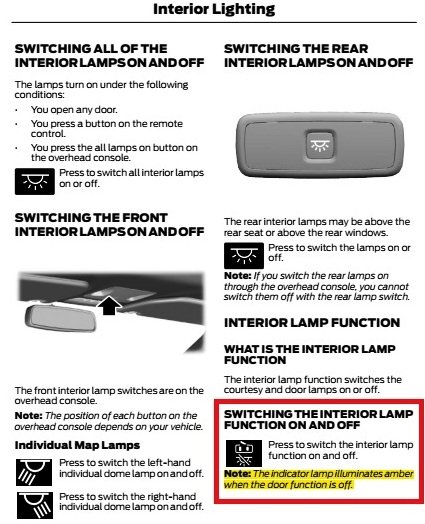
As @dabangsta describes, from page 103 of the 2024 Ford Edge Owner's Manual (PDF download link)... Good luck!
-
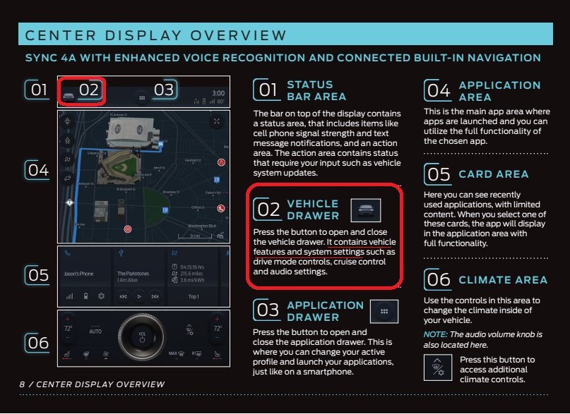
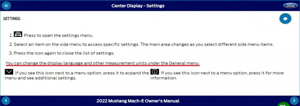
Welcome to the Ford Edge Forum, amer fatayer! There are many Mustang Mach-e discussion forums available to you... link to Web Search Listing. But as long as you're here... Document download links> 2022 Ford Mustang Mach-e Owner's Guide in English 2022 Ford Mustang Mach-e Quick Reference Guide in English Good luck!