


Haz
-
Posts
1,568 -
Joined
-
Last visited
-
Days Won
439
Content Type
Profiles
Forums
Gallery
Everything posted by Haz
-
Struts and shocks, Motorcraft or KYB?
Haz replied to jonesboys310's topic in Brakes, Chassis & Suspension
Link to this FordParts webpage Document download links> Shock Absorber and Spring Assembly - Removal and Installation - 2014 Edge Workshop Manual.pdf Cowl Panel Grille - Removal and Installation - 2014 Edge Workshop Manual.pdf Shock Absorber and Spring Assembly - Disassembly and Assembly -2014 Edge Workshop Manual.pdf Good luck!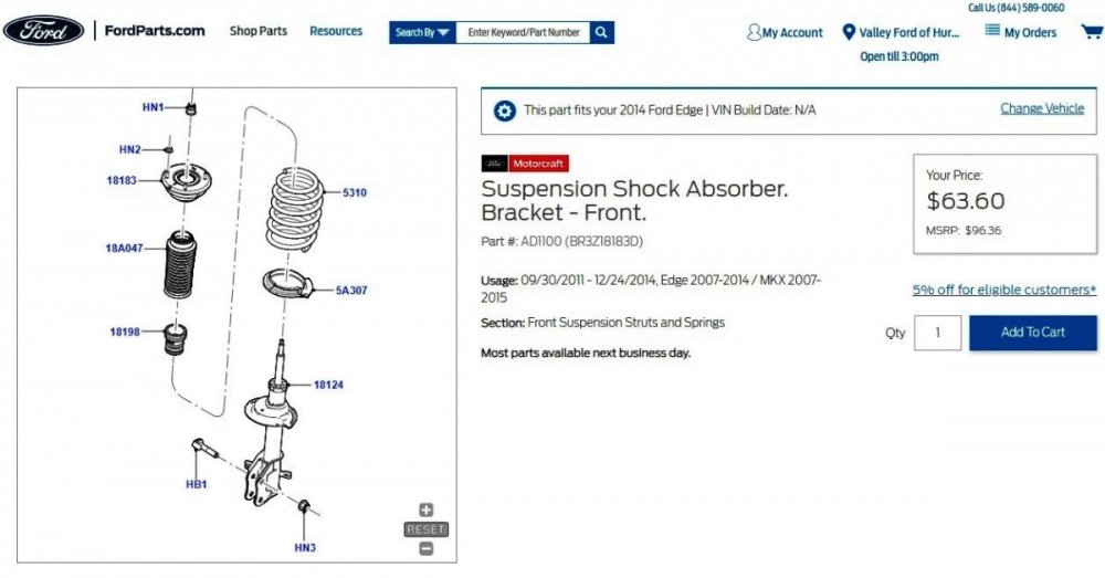
-
Factory installation instructions for 2015 Edge front bumper
Haz replied to Olwiseone's topic in Exterior & Body
Document download links> Front Bumper Cover - Removal and Installation - 2015 Edge Workshop Manual.pdf Front Bumper - Removal and Installation - 2015 Edge Workshop Manual.pdf Active Grille Shutter - Removal and Installation - 2015 Edge Workshop Manual.pdf Good luck! -
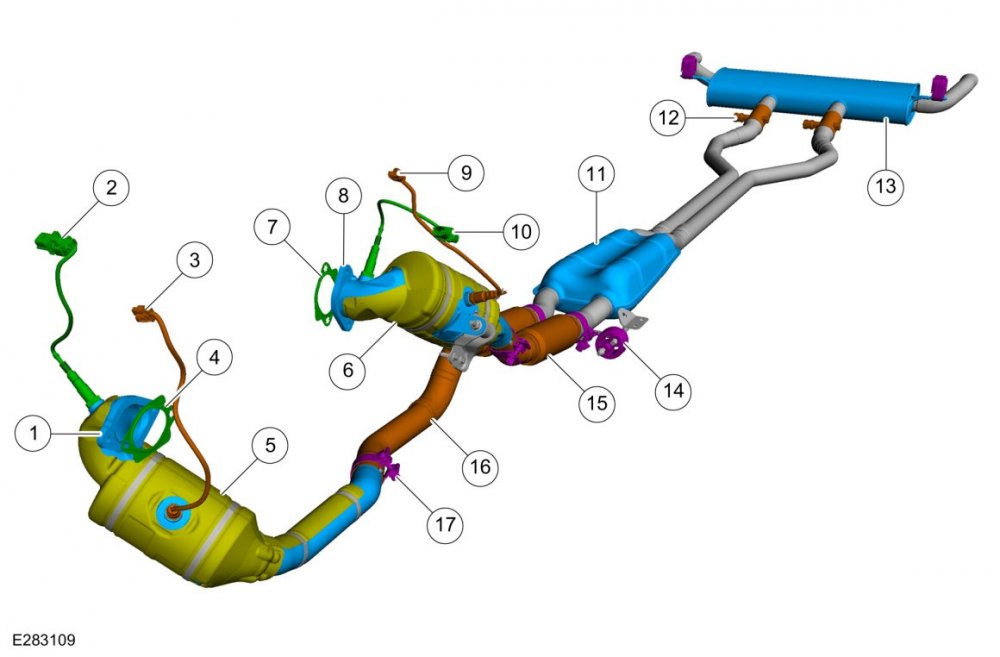
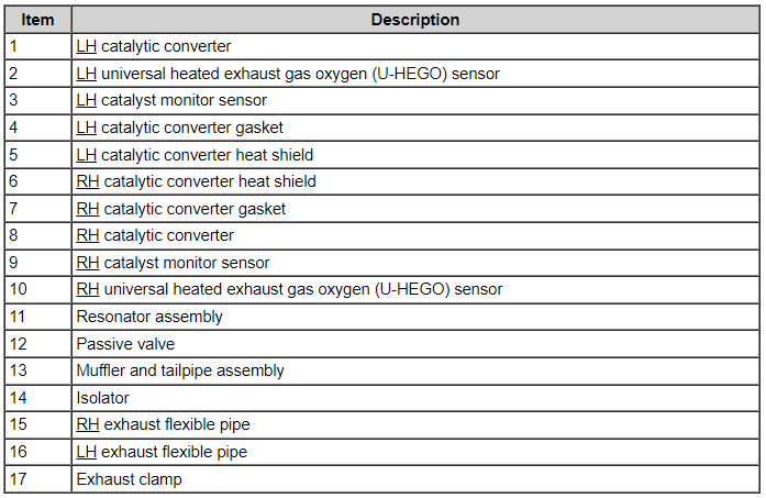
Document download link> Exhaust System - Component Location - 2.7L EcoBoost - 2019 Edge Workshop Manual.pdf Good luck!
-
Good luck!
-
From the 2019 Edge Workshop Manual... 309-00B Exhaust System - 2.7L EcoBoost (238kW/324PS) 2021 Edge Diagnosis and Testing Procedure revision date: 02/20/2020 Exhaust System Symptom Chart(s) Symptom Chart: Symptom Chart - Exhaust System Verify the customer concern. Inspect the components of the exhaust system for obvious signs of damage or other mechanical concerns using the following chart. Visual Inspection Chart - Mechanical Mechanical Exhaust pipe pinched or crushed Damaged muffler Broken or damaged exhaust hanger brackets Damaged catalytic converter Damaged exhaust passive valve Loose or damaged heat shields Verify the exhaust system is installed correctly, with clamps correctly located and tightened to specifications. If the fault is not visually evident, determine the symptom. GO to the Symptom Chart below. Symptom Chart: Symptom Chart - NVH Condition Possible Sources Actions Rattle, squeaks or buzz type noise — from the bottom of the vehicle Loose or damaged heat shield INSPECT the exhaust system for loose or missing heat shields or foreign material trapped between the heat shields and the exhaust system components. If any heat shields are loose, INSTALL worm gear clamp 7L5Z-5A231-AA and tighten to 7 Nm. If the heat shields are missing or a rattle, noise or buzz condition persists, INSTALL a new heat shield or component as necessary. Loose or damaged exhaust isolators VERIFY the exhaust isolators are correctly installed. INSPECT the exhaust isolators for wear or damage. INSTALL new isolators as necessary. Damaged exhaust isolator hanger bracket INSPECT the exhaust system components for damage or broken hangers. INSTALL new components as necessary. CHECK for loose or damaged exhaust hanger brackets or fasteners. TIGHTEN the bolts to specification or INSTALL new components as necessary. Loose or damaged catalytic converter or muffler MOVE the exhaust system to simulate the bouncing action of the vehicle, checking for exhaust-to-body contact while moving the exhaust system. Using a rubber mallet, TAP on the exhaust components to duplicate the noise concern. Lightly TAP on the muffler, then the catalytic converter. DETERMINE if there are loose or broken baffles in the muffler or a loose or broken element in the catalytic converter. REPAIR or INSTALL new components as necessary. Exhaust grounded to chassis INSPECT for signs of exhaust components-to-body contact. REPAIR or INSTALL new components as necessary. Exhaust passive valve INSPECT the operation of the exhaust passive valve. REPAIR or INSTALL new components as necessary. Drone or clunk type noise — from the bottom of the vehicle Loose or damaged exhaust isolators INSPECT the exhaust isolators for wear or damage. INSTALL new isolators as necessary. Exhaust grounded to chassis INSPECT for signs of exhaust components-to-body contact. REPAIR or INSTALL new components as necessary. Whistles, boom, hum or ticking type noise — noise tends to change as the engine warms. The noises are often accompanied by exhaust fumes Exhaust system leak INSPECT the entire exhaust system for leaks. CHECK for punctures, loose or damaged clamps/fasteners, gaskets, sensors or broken welds. EXAMINE the chassis for grayish-white or black exhaust soot, which indicates exhaust leakage at that point. To magnify a small leak, have an assistant hold a shop towel over the tail pipe outlet while listening for a leak. REPAIR or INSTALL new components as necessary. Catalytic converter MOVE the exhaust system to simulate the bouncing action of the vehicle, checking for exhaust-to-body contact while moving the exhaust system. Using a rubber mallet, TAP on the exhaust components to duplicate the noise concern. Lightly TAP on the muffler and the catalytic converter. DETERMINE if there are loose or broken baffles in the muffler, or a loose or broken element in the catalytic converter. REPAIR or INSTALL new components as necessary. Exhaust muffler/resonator drain hole enlarged due to corrosion CONFIRM the drain holes are the noise source. INSTALL new components as necessary. Hissing or rushing noise — high frequency sound and the vehicle performance is unaffected Exhaust system Exhaust flow through pipes CHECK the exhaust system for leaks. Using a rubber mallet, TAP on the exhaust components to duplicate the noise concern. Lightly TAP on the muffler and the catalytic converter. DETERMINE if there are loose or broken baffles in the muffler, or a loose or broken element in the catalytic converter. REPAIR or INSTALL new components as necessary. Pinging noise — occurs when exhaust system is hot, engine turned off Catalytic converter/exhaust system Cool down pinging is a result of the exhaust system expanding and contracting during heating and cooling. This is a normal condition. Vibration — occurs at idle and at low speeds. Also accompanied by a clunk or buzz type noise Loose or damaged exhaust isolator INSPECT the exhaust isolators for wear or damage. INSTALL new isolators as necessary. Loose or damaged exhaust isolator hanger brackets INSPECT the exhaust isolator hanger brackets for wear or damage. INSTALL or REPAIR as necessary. Exhaust system grounded to chassis REPAIR or INSTALL new components as necessary. Engine drumming noise — normally accompanied by vibration Damaged or misaligned exhaust system INSPECT the exhaust system for loose or damaged fasteners or isolators. REPAIR or INSTALL new components as necessary. Sputter type noise — noise worse when cold, lessens or disappears when the vehicle is at operating temperature Damaged or worn exhaust system INSPECT the exhaust system for leaks or damage. REPAIR as necessary. Thumping noise — from the bottom of the vehicle, worse during acceleration Misaligned exhaust system CHECK the exhaust system to chassis clearance. CHECK the exhaust system isolators for damage. REPAIR as necessary. Engine vibration — is felt with increases and decreases in engine rpm Strain on exhaust system isolators REPAIR or INSTALL new components as necessary. Drumming noise — occurs inside the vehicle during idle or high idle, hot or cold. Very low-frequency drumming is very rpm dependent Exhaust system vibration excites the body resonances inducing interior noise REPAIR or INSTALL new components as necessary. Good luck!
-
Additional... Document download links> Pinpoint Test DD - Fuel Rail Pressure (FRP) and Fuel Rail Pressure Temperature (FRPT) Sensors.pdf Pinpoint Test KC - Fuel Pump Control Module.pdf Good luck!
-
No personal insights to offer in this case, just subject-vehicle information and topical diagnostic procedures from Ford's 2010 Gasoline Powertrain Control / Emissions Diagnosis (PC/ED) Manual in this and another immediately following post, due to Forum file attachment limitations... Document download links> Fuel Charging and Controls - 2.5L - 2010 Escape-Mariner Workshop Manual.pdf Fuel System Pressure Release - General Procedures - 2010 Escape-Mariner Workshop Manual.pdf Quick Connect Coupling - General Procedures - 2010 Escape-Mariner Workshop Manual.pdf Fuel System Pressure Test - General Procedures - 2010 Escape-Mariner Workshop Manual.pdf Throttle Body - Removal and Installation - 2.5L - 2010 Escape-Mariner Workshop Manual.pdf Throttle Body - R&I Enhanced Image - 2.5L - 2010 Escape-Mariner Workshop Manual.pdf Fuel Rail and Fuel Injector - Exploded View - 2.5L - 2010 Escape-Mariner Workshop Manual.pdf Fuel Rail and Fuel Injector - Exploded View Enhanced Image #1 - 2.5L - 2010 Escape-Mariner Workshop Manual.pdf Fuel Rail and Fuel Injector - Exploded View Enhanced Image #2 - 2.5L - 2010 Escape-Mariner Workshop Manual.pdf Fuel Rail - Removal and Installation - 2010 Escape-Mariner Workshop Manual.pdf Fuel Pump Control Module - Removal and Installation - 2.5L - 2010 Escape-Mariner Workshop Manual.pdf
-
Document download links> IMAGE PROCESSING MODULE A (IPMA) - Connector C9224 Details - 2019 Edge.pdf IMAGE PROCESSING MODULE A (IPMA) - Connector C9224 Location - 2019 Edge.pdf IMAGE PROCESSING MODULE A (IPMA) - Wiring Diagram - 2019 Edge.pdf IMAGE PROCESSING MODULE A (IPMA) - Removal and Installation - 2019 Edge Workshop Manual.pdf IMAGE PROCESSING MODULE A (IPMA) - Removal and Installation - 2019 Edge Workshop Manual.pdf Lane Keeping System - System Operation and Component Description - 2019 Edge Workshop Manual.pdf Lane Keeping System - Component Location - 2019 Edge Workshop Manual.pdf Link to this FordParts webpage Good luck!
-
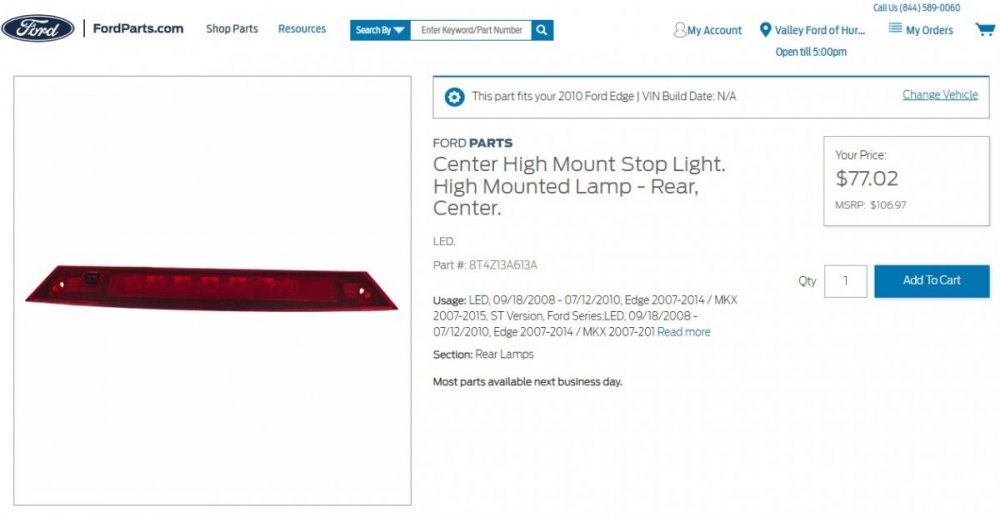
The 2007-2010 Edge wiring diagrams depict the lamps in the High Mounted Stop Lamp assembly as being conventional filament bulbs, while the 2011 Edge wiring diagram depicts LEDs. The currently offered Service replacement High Mounted Stop Lamp assembly is now LED for 2007-2014 Edge... Link to this FordParts web page Document download links> High Mounted Stop Lamp Wiring Diagram - 2007-2010 Edge.pdf High Mounted Stop Lamp Wiring Diagram - 2011-2014 Edge.pdf Wiring Diagram Symbols - Edge.pdf High Mounted Stop Lamp - Connector C904 Details - 2007-2014 Edge.pdf High Mounted Stop Lamp - Connector C904 Location - 2007-2014 Edge.pdf Good luck!
-
denny73: Nothing new specific to this topic, though there have been two unrelated UK Edition documents, consistent with Italy, recently released... Document download links> TSB 23-2379 - 2019-2022 Edge 2.0L EcoBlue - Illuminated AWD warning indicator or fault message with DTC C0095.pdf GSB 23-7123 - Various Models, Including Edge - Condensation inside the exterior lamp lens.pdf I think I'll try establishing an International Markets discussion thread to compile interested Forum members' Continent/Country SSM/GSB/TSB/Service-related releases. Based upon your inquiry, I'll start with EU/UK document editions and looking at Italy for commonality or uniqueness, but I'm willing to try expand to other Continent/Countries, based upon Forum member requests. If home-country language versions of documents are preferred. I may be able to accomplish that. Good luck!
-
From Ford's Service Awareness Newsletter for Dealership Service personnel... 12-Volt Battery Charging When charging the 12-volt battery on vehicles equipped with a battery monitoring sensor (BMS), the negative cable clamp of the battery charger must be connected to an engine or chassis ground as directed by the WSM (workshop manual) section 414-01> General Procedures> Battery Charging. Connecting the chargers’ negative cable clamp directly to the battery terminal will not allow the BMS to measure charging current flowing from the charger to the battery. Improper connection will result in the BMS SOC (state of charge) PID (parameter ID) failing to update to reflect the improved SOC. Never perform the BMS/SOC reset procedure unless the battery is replaced. The BMS should only be replaced if directed by the WSM. From Edge Workshop Manual... Battery Charging WARNING: Before beginning any service procedure in this section, refer to Safety Warnings in section 100-00 General Information. Failure to follow this instruction may result in serious personal injury. NOTE: Batteries will discharge due to normal parasitic key off-loads when the vehicle is on a dealer lot or parked by the customer for an extended period of time. Vehicles still in dealer inventory or in long-term storage may be driven short distances with heavy electrical loads. Over a period of time (30 days or more), this could result in vehicles having shallow or deeply discharged batteries. NOTE: The vehicle charging system is designed to supply the electrical power needed to maintain the battery near full charge during normal vehicle use. The charging system is not capable of bringing a deeply discharged battery back to near full charge in a short amount of time such as allowing the vehicle to idle for 15 minutes to recharge the battery. Use an external charger to charge discharged batteries. NOTE: Cold batteries will not readily accept a charge. Allow batteries to warm to approximately 5°C (41°F) before charging. This may require 4 to 8 hours at room temperature. Charger Connected to Engine or Chassis Ground - Preferred Method Connect the positive (red) charger clamp to the positive battery post. NOTICE: Do not connect the negative (black) charger clamp directly to the battery monitoring sensor, it must be connected to an engine or chassis ground to relearn the battery's state of charge. Connect the negative (black) charger clamp to the negative battery ground cable bolt or an engine ground. Charge the battery following the battery charger manufacturer's instructions.
-
From Ford's Service Awareness Newsletter for Dealership Service personnel... 2020-2024 Edge Wiper Motor Warranty Ford warranty has experienced several wiper motor replacement warranty claims that were the result of stripped wiper motor gears. It has been shown that wiper motor gears can strip as a result of customers improperly lifting up the wiper arms off of the windshield or manually pulling the wiper arms while the vehicle ignition is on. The Owner's Manual advises customers that the vehicle should be off before replacing the front wiper blades and has also recently been updated to caution customers to not manually move the wiper arms when the ignition is on or in accessory mode as this could damage the wiper motor. Stripped wiper motors will exhibit a grinding noise from the wiper motor with no wiper blade movement when turned on.
-
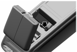
From Ford's Professional Technician System, this "What's New" advice to Dealership Service personnel... 2024 Nautilus Keypad Code Some 2024 Nautilus vehicles may incorrectly list the keypad code card on the loose item checklist. No keypad code cards were shipped or included in 2024 Nautilus vehicles for North America. To retrieve the vehicle’s keyless entry pad code, refer to the Keyless Entry Keypad Master Access Code section of the Owner’s Manual. This process will require the use of both programmed intelligent access keys. From the 2024 Nautilus Owner's Manual, pages 85-86... KEYLESS ENTRY KEYPAD MASTER ACCESS CODE What is the Master Access Code The master access code is a factory-set five-digit entry code. You can operate the keypad with the master access code at any time. The master access code can be displayed in the instrument cluster display and is available from an authorized dealer. Displaying the Master Access Code in the Instrument Cluster Display Read and understand the following before you begin the process. • You must have two previously programmed intelligent access key inside your vehicle. • Make sure that your vehicle is off. • Make sure you do not press the brake pedal during the procedure. • Make sure that you close all the doors and that they remain closed throughout the procedure. Perform all steps within 30 seconds of starting the sequence. If you perform any of the steps out of sequence, stop and wait for at least one minute before starting again. Note: Do not place the [Passive Key] device on the wireless accessory charging area during the procedure. 1. Access the backup slot. See Accessing the Passive Key Backup Position (page 190). 2. Place the first intelligent access key into the backup slot. 3. Press the push button ignition switch once and wait for a few seconds. 4. Press the push button ignition switch again and remove the intelligent access key from the center console. 5. Insert the second programmed intelligent access key into the backup slot in the center console, then press the push button ignition switch. The master access code appears in the instrument cluster display for a few seconds. Note: The code may not display until after other warning messages display From the 2024 Nautilus Owner's Manual, page 190... ACCESSING THE PASSIVE KEY BACKUP POSITION 1. Open the floor console storage compartment lid. 2. Place the passive key into the backup slot.
-
If your Edge is equipped with the Sony Audio System, the Sony Audio Digital Signal Processing (DSP) Module is mounted immediately behind the Loadspace Trim Panel that you have marked in your photo... Good luck!
Module-2016Edge.thumb.jpg.456e8085a1686aead642823c8dd54d3b.jpg)
-
Click on this link to download the full Removal and Installation procedure... Loadspace Trim Panel - Removal and Installation - 2016 Edge Workshop Manual.pdf Good luck!
-
Just in case you wish to remove a trim panel to confirm your discovery... Document download links> Loadspace Trim Panel - Removal and Installation - 2016 Edge Workshop Manual.pdf Liftgate Trim Panel - Removal and Installation - 2016 Edge Workshop Manual.pdf Good luck!
-
Document download links> Fog Lamps Ground Circuit - G111 Terminating Location - 2019 Edge.pdf Fog Lamps Ground Circuit - Splice S189 Location - 2019 Edge.pdf Good luck!
-
Document download links> FOG LAMP, LEFT FRONT - Connector C152 Location - 2019 Edge.pdf FOG LAMP, RIGHT FRONT - Connector C162 Location - 2019 Edge.pdf
-
The body shop should be assessing fog lamp circuits wiring, harness connectors, and grounds termination. Right hand fog lamp wiring is contained in harness that routes inside the bumper cover to connector & ground on the left hand front corner of engine compartment. If animal impact damaged bumper cover, then perhaps harness was damaged, If repair required removal of the bumper cover, then perhaps connector pin was damaged or pushed out when connectors and the front end was reassembled. The body shop should be capable of chasing down the wiring/connector/ground issue caused by the original impact or by a reassembly mishap. The following Workshop Manual & Wiring resources should improve your awareness and equip the body shop techs to correct the problem... Document download links> Fog Lamps - Diagnosis and Testing - 2019 Edge Workshop Manual.pdf Fog Lamps Wiring Diagram -2019 Edge.pdf Front End Ground Circuits, Including Fog Lamps Ground - Wiring Diagram - 2019 Edge.pdf FOG LAMP, LEFT FRONT - Connector C152 Details - 2019 Edge.pdf FOG LAMP, RIGHT FRONT - Connector C162 Details - 2019 Edge.pdf Fog Lamps Power Circuit - Pins 15 (LH) & 16 (RH) of Inline Connector C140 - 2019 Edge.pdf BODY CONTROL MODULE (BCM) - Connector C2280B Details - 2019 Edge.pdf Front Bumper Cover - Disassembly and Assembly - 2019 Edge Workshop Manual.pdf Front Bumper Cover - Removal and Installation - 2019 Edge Workshop Manual.pdf Additional resources will be provided in immediately following posts...
-
Need help with inop heated seats and dcsm location
Haz replied to Rededge98290's topic in Interior, A.C., Heat, Interior Trim
Per Rededge98290's request... "It looks like the simplest cause to both seats not heating would be the failure of ground G302. Would you be able to share the location of that? If that's not the issue, then I'll dig into the step by step pinpoints" Document download links> Heated Seats - Ground G302 Location - Right Hand B-Pillar - 2013 Edge.pdf B-Pillar Trim Panel - Removal and Installation - 2013 Edge Workshop Manual.pdf Scuff Plate Trim Panel, Front - Removal and Installation - 2013 Edge Workshop Manual.pdf Scuff Plate Trim Panel, Rear - Removal and Installation - 2013 Edge Workshop Manual.pdf Good luck! -
Door Buttons Not Illuminated - Is This Normal?
Haz replied to McGruber's topic in Interior, A.C., Heat, Interior Trim
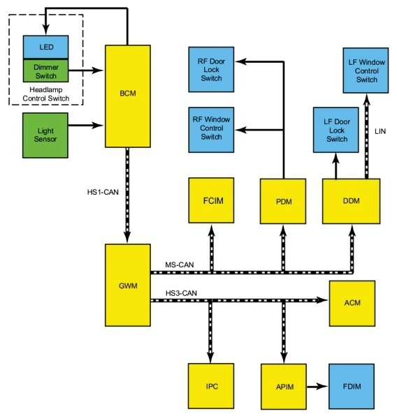
Welcome to the Forum, McGruber ! I'm curious if your headlamps were set to Autolamp, and if ignition was "on" with or without the engine running? The 2020 Edge Workshop Manual states door-panel switch backlighting is activated when parking lamps are "on", though parking lamps and dimmable backlighting are also temporarily "on" during Illuminated Entry and Exit, as described below... Placing your device cursor over underlined acronyms may yield full-word descriptions. Instrument Panel and Interior Switches Illumination System Operation System Diagram - Networked Illumination Network Message Chart Module Network Input Messages - ACM , APIM , DDM , FCIM , GWM , IPC and PDM . Broadcast Message Originating Module Message Purpose Illumination Dimming Level BCM Used to command the illumination dimming level for networked modules and outputs that are hardwired to networked modules. Networked Illumination Operation The dimmable switches and components are illuminated when the parking lamps are on. The system-wide illumination dimming level is determined by the BCM . Based on the ambient light level input from the light sensor and the requested illumination dimming level input from the dimmer switch, the BCM calculates the correct dimming level. The BCM sends the illumination dimming level message to the GWM on the HS-CAN1 . The GWM distributes the message to the following components: MS-CAN FCIM DDM PDM HS-CAN3 IPC APIM ACM The receiving modules use the illumination dimming level message to determine the backlighting intensity of internal and external non-networked illumination sources. If a module does not receive the illumination dimming level message or the data received is deemed invalid, the module sets a DTC in continuous memory and defaults to full nighttime intensity. If the IPC does not receive the dimming level or ambient light level network messages from the BCM for up to 5 seconds, the IPC illumination remains at the last level based on the last message received. If the IPC receives invalid or no signals for more than 5 seconds, the IPC defaults to full night illumination level. On vehicles equipped with autolamps, if the exterior lamps are activated during the daytime, the message center illumination remains at full intensity and does not dim from the illumination dimmer switch. If the vehicle travels under a bridge or through a tunnel, the low level of ambient light causes the illumination level of the message center to change to the level set by the illumination panel dimmer switch. The message center illumination changes back to full intensity when the intense ambient light is restored. The hazard switch is integral to the FCIM and cannot be serviced separately. System Diagram - Non-Networked Illumination Non-Networked Illumination Operation Based on the ambient light level input from the light sensor and the requested illumination dimming level input from the dimmer switch, the BCM calculates the correct dimming level for the non-networked illumination sources. The BCM provides a pulse-width modulated voltage to all non-networked illumination sources on two circuits. Field-Effect Transistor (FET) Protection Field-Effect Transistor (FET) protection is used to protect the BCM output drivers from damage in the event an excessive current draw is detected on a BCM output. Each illumination circuit connected to the BCM is separately protected. Refer to the System Diagram in this section to view the different groups of BCM non-networked illumination outputs. Component Description Dimmer Switch The illumination dimmer switch is a momentary contact switch that is integral to the headlamp switch. The headlamp switch is non-networked to the BCM . When the illumination dimmer switch is pressed up or down, the switch completes a ground circuit to the BCM corresponding to the desired action (increase or decrease illumination brightness). Field Effect Transistor (FET) Protection The BCM utilizes an Field Effect Transistor (FET) protective circuit strategy for many of its outputs, for example, lamp output circuits. Output loads (current level) are monitored for excessive current (typically short circuits) and are shut down (turns off the voltage or ground provided by the module) when a fault event is detected. A Field Effect Transistor (FET) is a type of transistor that the control module software uses to control and monitor current flow on module outputs. The Field Effect Transistor (FET) protection strategy prevents module damage in the event of excessive current flow. Output loads (current level) are monitored for excessive current draw (typically short circuits). When a fault event is detected the Field Effect Transistor (FET) turns off and a short circuit DTC sets. The module resets the Field Effect Transistor (FET) protection and allows the circuit to function when the fault is corrected or the ignition state is cycled off and then back on. When the excessive circuit load occurs often enough, the module shuts down the output until a repair procedure is carried out. Each Field Effect Transistor (FET) protected circuit has three predefined levels of short circuit tolerance based on a module lifetime level of fault events based upon the durability of the Field Effect Transistor (FET). If the total tolerance level is determined to be 600 fault events, the three predefined levels would be 200, 400 and 600 fault events. When each level is reached, the DTC associated with the short circuit sets along with DTC U1000:00. These Diagnostic Trouble Codes (DTCs) can be cleared using the module on-demand self-test, then the Clear DTC operation on the scan tool (if the on-demand test shows the fault corrected). The module never resets the fault event counter to zero and continues to advance the fault event counter as short circuit fault events occur. If the number of short circuit fault events reach the third level, then Diagnostic Trouble Codes (DTCs) U1000:00 and U3000:49 set along with the associated short circuit DTC . DTC U3000:49 cannot be cleared and the module must be replaced after the repair. Interior Lighting - System Operation Illuminated Entry and Exit The illuminated entry and exit features provide temporary illumination of the parking lamps, the dimmable backlighting, the ambient backlighting and the courtesy lamps. Refer to the table for additional information. NOTE: An arbitrator (software programming) within the BCM determines which actions take precedence over others (for example, an open door keeps the courtesy lamps on even when a command to lock the doors is received). Action Parking Lamps Courtesy Lamps Dimmable Backlighting Ambient Lighting RKE transmitter or mechanical unlocking of the doors On for 25 seconds On for 25 seconds On for 25 seconds Off RKE transmitter or mechanical locking of the doors Off Off Off Off 3 seconds after courtesy lamps turned off Open a closed door after previously unlocking (no ignition state change since unlock) Off (on for remaining time if unlocked from transmitter or mechanical unlocking of the doors) On Off On Close all doors Off On for 25 seconds On for 25 seconds On for 25 seconds Ignition changed to ON Off On for 25 seconds Off On Ignition changed out of ON Off On for 25 seconds On for 25 seconds On for 25 seconds Open a door after the ignition is changed to OFF Off On Off On (color is red on the open door) Ignition is OFF and doors are unlocked from the door lock switch Off On for 25 seconds Off Off Ignition is OFF and doors are locked from the door lock switch Off Off Off Off Good luck!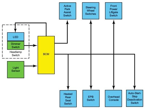
-
Need help with inop heated seats and dcsm location
Haz replied to Rededge98290's topic in Interior, A.C., Heat, Interior Trim
Additional diagnostic document download links> HEATED SEAT ELEMENT, RIGHT FRONT - Connector 3284 Location - 2013 Edge.pdf HVAC MODULE, DATC - Connector 228A Location - 2013 Edge.pdf HVAC MODULE, DATC - Connector 228B Location - 2013 Edge.pdf Battery Junction Box (BJB) Diagram - 2013 Edge.pdf Battery Junction Box (BJB) Fuse-Circuit Legend - 2013 Edge.pdf Good luck! -
Need help with inop heated seats and dcsm location
Haz replied to Rededge98290's topic in Interior, A.C., Heat, Interior Trim
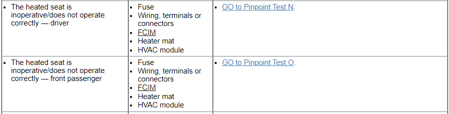
Welcome to the Forum, Rededge ! You were unsuccessful finding a DCSM on your front seat heat-only 2013 Edge Limited because the Dual Climate Seat Module (DCSM) is only installed on vehicles equipped with heated-and-cooled (dual climate) seats. So, there's no DCSM hidden on your vehicle, though on vehicles with dual climate seats, the DCSM is mounted under the passenger seat. From the 2013 Edge Workshop Manual... Front Seats - Heated Seats WARNING: Never install heated seat parts not intended for use on this vehicle. Parts released for other model years or vehicle lines are not compatible even if they appear visually and physically similar. Installing incorrect parts will result in heated seat system performance outside design specification. Failure to follow this instruction may result in serious personal injury. This system allows independent seat electrical heating of each front seat on demand. The components of the system are: seat heater mats located on the seat cushion and backrest. the HVAC module heated seat buttons, located on the touchscreen interface (if equipped) or the Front Controls Interface Module (FCIM) . temperature sensors, located in the seat cushion heater mats. A new heater mat comes assembled on a new foam pad. The driver and passenger heated seat control buttons and indicators are located on the Front Controls Interface Module (FCIM) or touchscreen interface (if equipped). The heated seat system functions independently of the vehicle's climate control system. Each time the heated seat button is pressed, the FCIM sends the request message to the HVAC module which decreases one setting (the sequence is hi, low, OFF, hi, etc.). For vehicles without a touchscreen interface, when a heated seat is set to hi, both LED indicators above that heated seat's control button illuminate. When a heated seat is set to low, only one LED indicator above that switch illuminates. When off, no indicators illuminate. When activated, the HVAC module supplies voltage to the selected seat's heater circuit. Each seat's cushion heater mat and backrest heater mat is connected in a series circuit to the HVAC module and powered by the output circuit for that seat. The HVAC module monitors inputs from a temperature sensor located in each seat's cushion heater mat, and maintains seat temperature by cycling the heater circuits on/off. The heated seat remains ON until the heated seat switch button is pressed to cycle the HVAC module OFF or the ignition is set to OFF. If a fault is detected by the HVAC module, the module stops supplying voltage to that individual left or right seat that the fault was detected on until the ignition is turned OFF and then ON. Diagnostic document download links> Heated Seat Is Inoperative - Driver & Passenger Diagnostic Pinpoint Tests ''N'' & ''O'' - 2013 Edge Workshop Manual.pdf Heated Seats - Wiring Diagram Cell 119 - 2013 Edge.pdf Supplemental Restraint System (SRS) Depowering and Repowering - General Procedures - 2013 Edge Workshop Manual.pdf HEATED SEAT ELEMENT, RIGHT FRONT - Connector 3284 Details - 2013 Edge.pdf HEATED SEAT ELEMENT, LEFT FRONT - Connector 3283 Details - 2013 Edge.pdf HEATED SEAT ELEMENT, LEFT FRONT - Connector 3283 Location - 2013 Edge.pdf HVAC MODULE, DATC - Connector 228A Details - 2013 Edge.pdf HVAC MODULE, DATC - Connector 228B Details - 2013 Edge.pdf Driver Seat Side Air Bag - Inline Connector C328 Details - 2013 Edge.pdf Driver Seat Side Air Bag - Inline Connector C328 Location - 2013 Edge.pdf HVAC MODULE, DATC - Connector 228A Details - 2013 Edge.pdf HVAC MODULE, DATC - Connector 228B Details - 2013 Edge.pdf Driver Seat Side Air Bag - Inline Connector C328 Details - 2013 Edge.pdf Driver Seat Side Air Bag - Inline Connector C328 Location - 2013 Edge.pdf Passenger Seat Side Air Bag - Inline Connector C327 Details - 2013 Edge.pdf Passenger Seat Side Air Bag - Inline Connector C327 Location - 2013 Edge.pdf Body Control Module (BCM) - Removal and Installation - 2013 Edge Workshop Manual.pdf Body Control Module (BCM) - R & I Enhanced Image #1 - 2013 Edge Workshop Manual.pdf Body Control Module (BCM) - R & I Enhanced Image #2 - 2013 Edge Workshop Manual.pdf Heating Ventilation Air Conditioning (HVAC) Module - Removal and Installation - 2013 Edge Workshop Manual.pdf Heating Ventilation Air Conditioning (HVAC) Module - R & I Enhanced Image #1 - 2013 Edge Workshop Manual.pdf Heating Ventilation Air Conditioning (HVAC) Module - R & I Enhanced Image #2 - 2013 Edge Workshop Manual.pdf Heating Ventilation Air Conditioning (HVAC) Module - R & I Enhanced Image #3 - 2013 Edge Workshop Manual.pdf Additional diagnostic documents will be provided in my next post...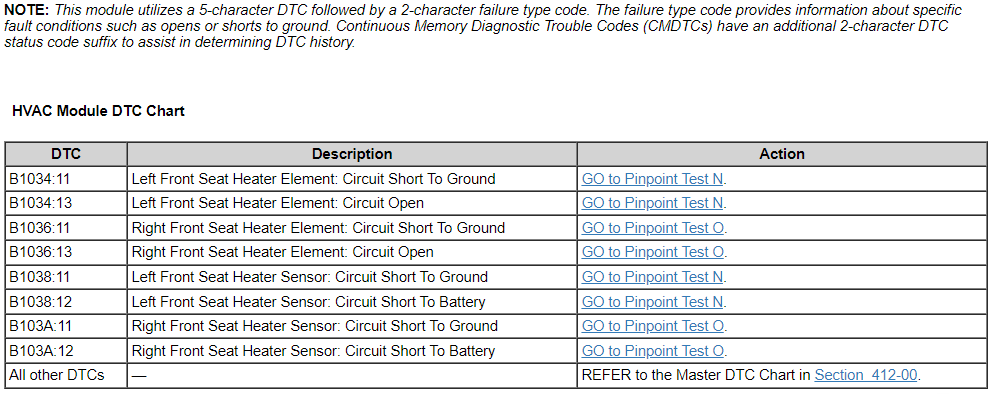

-
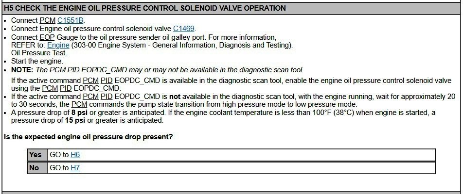
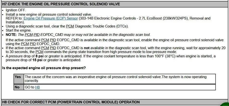
Perhaps your Workshop Manual extract is from prior to October 15, 2019, when that 2015 Specifications page was revised... Oil Pressure NOTE: The following oil pressure readings are acquired using a scan tool and monitoring the EOP_PRESS PID. Item Specification Reading 1: Minimum average oil pressure @ 2,000 rpm after 15 secs with engine at normal operating temperature and transmission in Park 21 psi (144.8 kPa) Reading 2: Minimum average oil pressure @ 2,000 rpm after 15 secs with engine at normal operating temperature and transmission in Park (Oil Pressure Control Solenoid connector disconnected) Reading 1 value plus 8 psi (55.1 kPa) Your supposition on the Oil Pressure Control Solenoid affect is confirmed by Steps 5 & 7 of Electronic Engine Controls diagnostic Pinpoint Test H... Document download link> Oil Pressure Control Solenoid Removal and Installation - 2015 Edge Workshop Manual, Revised 01-09-2015.pdf (consistent with 2016 Edge Workshop Manual) Good luck! Edit: I neglected to include... DTC Fault Trigger Condition-PCM DTC Description Fault Trigger Conditions P06DA Engine Oil Pressure Control Circuit/Open Sets when the PCM detects an open on the engine oil pressure control solenoid valve circuit. P06DB Engine Oil Pressure Control Circuit Low Sets when the PCM detects a short to ground on the engine oil pressure control solenoid valve circuit. P06DC Engine Oil Pressure Control Circuit High Sets when the PCM detects a short to voltage on the engine oil pressure control solenoid valve circuit. P06DD Engine Oil Pressure Control Circuit Performance/Stuck Off Sets when the PCM detects the engine oil pressure control solenoid valve is stuck. Possible Sources Engine oil pressure control solenoid valve PCM Wiring, terminals or connectors

-
Sunroof rear brackets loose (Gen2)
Haz replied to omar302's topic in Glass, Lenses, Lighting, Mirrors, Sunroof (BAMR), Wipers
No related TSBs found, with this being the only communicated 2016 Edge Sunroof noise/vibration/harshness issue... SSM 49679 2015-2020 Edge, 2016-2018 MKX, 2019-2020 Nautilus - NVH Concerns After Replacement Of Roof Opening Panel Frame Some 2015-2020 Edge, 2016-2018 MKX, and 2019-2020 Nautilus vehicles may require replacement of the roof opening panel track or frame for various conditions. When replacing the roof opening panel, the replacement component may have less magnet plates. In order to prevent any noise vibration or harshness (NVH) concerns, the magnets on the headliner around the roof opening panel that line up with the removed magnet plates should be discarded. Good luck!


Module-2016Edge.jpg.f6a984e8b11e39b7c1c20790e8bdcd24.jpg)