Haz
-
Posts
1,568 -
Joined
-
Last visited
-
Days Won
436
Content Type
Profiles
Forums
Gallery
Everything posted by Haz
-
Presuming you will have your dealer's Service department resolve this issue, this from the 2022 Edge Workshop Manual is just an FYI... BCM DTC Fault Trigger Conditions B108A:9E Start Button: Signal Stuck On Sets continuous when the BCM detects only one switch input circuit indicating open when the start button is released. Possible Causes Battery voltage concern Fuse Wiring, terminals or connectors PATS concern Push button ignition switch BCM Good luck!
-
Heated/cooled seat stopped working 2016 Edge sport B272C
Haz replied to 68lemans462's topic in 2016 Edge & MKX
The following are document download links to relevant sections of the 2016 Edge Workshop Manual, including part numbers for wiring connector repair kits... Front Seat Climate Control Module [SCME] - Wiring Diagram - 2016 Edge Workshop Manual.pdf Front Seat Climate Control Module [SCME] - Connector C3265A Details - 2016 Edge Workshop Manual.pdf Front Seat Climate Control Module [SCME] - Connector C3265B Details - 2016 Edge Workshop Manual.pdf Front Seat Climate Control Module [SCME] - Connector C3265C Details - 2016 Edge Workshop Manual.pdf Good luck! -
Replaced 2011 MKX Battery - Ambient Temperature Not Working
Haz replied to Gustafa's topic in 2011 Edge & MKX
Letting it sit unaffected for eight hours does the job for the BCM -- no worries! Your Edge behaving normally is a good thing from which you should gain confidence. Good luck! -
Replaced 2011 MKX Battery - Ambient Temperature Not Working
Haz replied to Gustafa's topic in 2011 Edge & MKX
For future reference, from the 2011 Edge/MKX Workshop Manual... Carry out the Battery Monitoring System (BMS) Reset using the scan tool after the battery is connected. If the BMS Reset is not carried out, it takes approximately 8 hours for the Body Control Module (BCM) to learn the new battery state of charge. During this 8 hour period, the vehicle must be undisturbed, with no doors opened or keyless entry button presses. If the vehicle is used before the BCM is allowed to learn the new battery state of charge, engine off load shedding can still occur and a message may be displayed. Additionally, the 2011 Edge/MKX's Ambient Air Temperature Sensor is located behind the grille, and removal of the Bumper Cover is required for access to the sensor... Ambient air temperature sensor Good luck!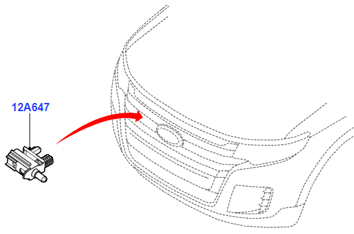

-
If you discover any DTC(s) that indicate further investigation is needed, just post it here and I'll provide you the Pinpoint Test information. Good luck!
-
Download link... 2009 Lincoln MKX Sales Brochure.pdf Good luck!
-
No, that is not normal engine noise, even at nearly twice the mileage (video link). Good luck!
-
Horn not working 2012 SEL
Haz replied to 12SEL's topic in Alarms, Keyless Entry, Locks & Remote Start
Try checking voltage using methods A8 and A9, below, using the Remote Keyless Entry (RKE) Lock command that is producing the marginal horn response, to see if voltage differs from horn actuation using the steering wheel method. Perhaps the brief electrical pulse to produce the horn chirp is being hampered by the horn's ground circuit, G107, depicted in the Wiring diagram above... From the 2011 Edge Workshop Manual... Remote Keyless Entry (RKE) Lock/Unlock Control — Lock The RKE feature requests that all of the doors be locked when the lock button is pressed. On any press of the lock button with all doors closed, the doors lock and the turn signals flash one time. If any door or liftgate is ajar, no flash occurs. As soon as the last door or liftgate is closed, the turn signals flash. If 2 presses of the lock button are received within 3 seconds, the horn chirps once and the turn signals flash twice to indicate that all of the doors and liftgate are closed and locked. If any door is ajar when the second lock request is received within 3 seconds of the first, the RKE transmitter feature chirps the horn twice without flashing the turn signals to indicate it locked all of the doors but one or more doors or the liftgate is ajar. When the ignition is in the RUN or START position, the turn signal flashes and horn chirp confirmations do not occur. A8 CHECK FOR VOLTAGE TO THE HORN Disconnect: Horn C131 . While pressing the horn switch, measure the voltage between the horn C131-2, circuit SRH01 (YE/RD), harness side and ground. Is the voltage greater than 10 volts? Yes GO to A9. No GO to A10. A9 CHECK THE HORN GROUND CIRCUIT FOR CONTINUITY While pressing the driver airbag module against the steering wheel, measure the voltage between the horn C131-2, circuit SRH01 (YE/RD), harness side, and the horn C131-1, circuit GD123 (BK/GY), harness side. Is the voltage greater than 10 volts? Yes INSTALL a new horn. REFER to Horn in this section. TEST the system for normal operation. No REPAIR circuit GD123 (BK/GY) for an open. TEST the system for normal operation. Good luck! -
Before replacing the speed sensors, did you scan or have your Edge scanned for Diagnostic Trouble Codes (DTCs) ? The ABS module has an extensive list of DTCs that can be helpful toward pinpointing the cause of false ABS activation. From the 2011 Edge Workshop Manual... ABS Module DTC Chart DTC Description Action C0001:49 TCS Control Channel "A" Valve 1: Internal Electronic Failure This DTC indicates that part of the ABS module has failed internally. CLEAR the DTCs. REPEAT the self-test. If DTC C0001:49 returns: For vehicles without adaptive cruise control, INSTALL a new ABS module. REFER to Anti-Lock Brake System (ABS) Module in this section. TEST the system for normal operation. For vehicles with adaptive cruise control, INSTALL a new HCU . REFER to Hydraulic Control Unit (HCU) in this section. TEST the system for normal operation. C0002:49 TCS Control Channel "A" Valve 2: Internal Electronic Failure This DTC indicates that part of the ABS module has failed internally. CLEAR the DTCs. REPEAT the self-test. If DTC C0002:49 returns: For vehicles without adaptive cruise control, INSTALL a new ABS module. REFER to Anti-Lock Brake System (ABS) Module in this section. TEST the system for normal operation. For vehicles with adaptive cruise control, INSTALL a new HCU . REFER to Hydraulic Control Unit (HCU) in this section. TEST the system for normal operation. C0003:49 TCS Control Channel "B" Valve 1: Internal Electronic Failure This DTC indicates that part of the ABS module has failed internally. CLEAR the DTCs. REPEAT the self-test. If DTC C0003:49 returns: For vehicles without adaptive cruise control, INSTALL a new ABS module. REFER to Anti-Lock Brake System (ABS) Module in this section. TEST the system for normal operation. For vehicles with adaptive cruise control, INSTALL a new HCU . REFER to Hydraulic Control Unit (HCU) in this section. TEST the system for normal operation. C0004:49 TCS Control Channel "B" Valve 2: Internal Electronic Failure This DTC indicates that part of the ABS module has failed internally. CLEAR the DTCs. REPEAT the self-test. If DTC C0004:49 returns: For vehicles without adaptive cruise control, INSTALL a new ABS module. REFER to Anti-Lock Brake System (ABS) Module in this section. TEST the system for normal operation. For vehicles with adaptive cruise control, INSTALL a new HCU . REFER to Hydraulic Control Unit (HCU) in this section. TEST the system for normal operation. C0010:49 Left Front Inlet Control: Internal Electronic Failure This DTC indicates that part of the ABS module has failed internally. CLEAR the DTCs. REPEAT the self-test. If DTC C0010:49 returns: For vehicles without adaptive cruise control, INSTALL a new ABS module. REFER to Anti-Lock Brake System (ABS) Module in this section. TEST the system for normal operation. For vehicles with adaptive cruise control, INSTALL a new HCU . REFER to Hydraulic Control Unit (HCU) in this section. TEST the system for normal operation. C0011:49 Left Front Outlet Control: Internal Electronic Failure This DTC indicates that part of the ABS module has failed internally. CLEAR the DTCs. REPEAT the self-test. If DTC C0011:49 returns: For vehicles without adaptive cruise control, INSTALL a new ABS module. REFER to Anti-Lock Brake System (ABS) Module in this section. TEST the system for normal operation. For vehicles with adaptive cruise control, INSTALL a new HCU . REFER to Hydraulic Control Unit (HCU) in this section. TEST the system for normal operation. C0014:49 Right Front Inlet Control: Internal Electronic Failure This DTC indicates that part of the ABS module has failed internally. CLEAR the DTCs. REPEAT the self-test. If DTC C0014:49 returns: For vehicles without adaptive cruise control, INSTALL a new ABS module. REFER to Anti-Lock Brake System (ABS) Module in this section. TEST the system for normal operation. For vehicles with adaptive cruise control, INSTALL a new HCU . REFER to Hydraulic Control Unit (HCU) in this section. TEST the system for normal operation. C0015:49 Right Front Outlet Control: Internal Electronic Failure This DTC indicates that part of the ABS module has failed internally. CLEAR the DTCs. REPEAT the self-test. If DTC C0015:49 returns: For vehicles without adaptive cruise control, INSTALL a new ABS module. REFER to Anti-Lock Brake System (ABS) Module in this section. TEST the system for normal operation. For vehicles with adaptive cruise control, INSTALL a new HCU . REFER to Hydraulic Control Unit (HCU) in this section. TEST the system for normal operation. C0018:49 Left Rear Inlet Control: Internal Electronic Failure This DTC indicates that part of the ABS module has failed internally. CLEAR the DTCs. REPEAT the self-test. If DTC C0018:49 returns: For vehicles without adaptive cruise control, INSTALL a new ABS module. REFER to Anti-Lock Brake System (ABS) Module in this section. TEST the system for normal operation. For vehicles with adaptive cruise control, INSTALL a new HCU . REFER to Hydraulic Control Unit (HCU) in this section. TEST the system for normal operation. C0019:49 Left Rear Outlet Control: Internal Electronic Failure This DTC indicates that part of the ABS module has failed internally. CLEAR the DTCs. REPEAT the self-test. If DTC C0001:49 returns: For vehicles without adaptive cruise control, INSTALL a new ABS module. REFER to Anti-Lock Brake System (ABS) Module in this section. TEST the system for normal operation. For vehicles with adaptive cruise control, INSTALL a new HCU . REFER to Hydraulic Control Unit (HCU) in this section. TEST the system for normal operation. C001C:49 Right Rear Inlet Control: Internal Electronic Failure This DTC indicates that part of the ABS module has failed internally. CLEAR the DTCs. REPEAT the self-test. If DTC C001C:49 returns: For vehicles without adaptive cruise control, INSTALL a new ABS module. REFER to Anti-Lock Brake System (ABS) Module in this section. TEST the system for normal operation. For vehicles with adaptive cruise control, INSTALL a new HCU . REFER to Hydraulic Control Unit (HCU) in this section. TEST the system for normal operation. C001D:49 Right Rear Outlet Control: Internal Electronic Failure This DTC indicates that part of the ABS module has failed internally. CLEAR the DTCs. REPEAT the self-test. If DTC C001D:49 returns: For vehicles without adaptive cruise control, INSTALL a new ABS module. REFER to Anti-Lock Brake System (ABS) Module in this section. TEST the system for normal operation. For vehicles with adaptive cruise control, INSTALL a new HCU . REFER to Hydraulic Control Unit (HCU) in this section. TEST the system for normal operation. C0020:11 ABS Pump Motor Control: Circuit Short To Ground This DTC indicates that part of the HCU has failed internally. CLEAR the DTCs. TEST DRIVE the vehicle. REPEAT the self-test. If C0020:11 returns, INSTALL a new HCU . REFER to Hydraulic Control Unit (HCU) in this section. TEST the system for normal operation. C0020:12 ABS Pump Motor Control: Circuit Short To Battery This DTC indicates that part of the HCU has failed internally. CLEAR the DTCs. TEST DRIVE the vehicle. REPEAT the self-test. If C0020:12 returns, INSTALL a new HCU . REFER to Hydraulic Control Unit (HCU) in this section. C0020:13 ABS Pump Motor Control: Circuit Open GO to Pinpoint Test A. C0020:71 ABS Pump Motor Control: Actuator Stuck GO to Pinpoint Test A. C0030:07 Left Front Tone Wheel: Mechanical Failure GO to Pinpoint Test B. C0031:01 Left Front Wheel Speed Sensor: General Electrical Failure GO to Pinpoint Test D. C0031:19 Left Front Wheel Speed Sensor: Circuit Current Above Threshold GO to Pinpoint Test D. C0031:29 Left Front Wheel Speed Sensor: Signal Invalid GO to Pinpoint Test B. C0031:2F Left Front Wheel Speed Sensor: Signal Erratic GO to Pinpoint Test B. C0031:64 Left Front Wheel Speed Sensor: Signal Plausibility Failure GO to Pinpoint Test B. C0033:07 Right Front Tone Wheel: Mechanical Failure GO to Pinpoint Test B. C0034:01 Right Front Wheel Speed Sensor: General Electrical Failure GO to Pinpoint Test D. C0034:19 Right Front Wheel Speed Sensor: Circuit Current Above Threshold GO to Pinpoint Test D. C0034:29 Right Front Wheel Speed Sensor: Signal Invalid GO to Pinpoint Test B. C0034:2F Right Front Wheel Speed Sensor: Signal Erratic GO to Pinpoint Test B. C0034:64 Right Front Wheel Speed Sensor: Signal Plausibility Failure GO to Pinpoint Test B. C0036:07 Left Rear Tone Wheel: Mechanical Failure GO to Pinpoint Test B. C0037:01 Left Rear Wheel Speed Sensor: General Electrical Failure GO to Pinpoint Test D. C0037:19 Left Rear Wheel Speed Sensor: Circuit Current Above Threshold GO to Pinpoint Test D. C0037:29 Left Rear Wheel Speed Sensor: Signal Invalid GO to Pinpoint Test B. C0037:2F Left Rear Wheel Speed Sensor: Signal Erratic GO to Pinpoint Test B. C0037:64 Left Rear Wheel Speed: Sensor Signal Plausibility Failure GO to Pinpoint Test B. C0039:07 Right Rear Tone Wheel: Mechanical Failure GO to Pinpoint Test B. C003A:01 Right Rear Wheel Speed Sensor: General Electrical Failure GO to Pinpoint Test D. C003A:19 Right Rear Wheel Speed Sensor: Circuit Current Above Threshold GO to Pinpoint Test D. C003A:29 Right Rear Wheel Speed Sensor: Signal Invalid GO to Pinpoint Test B. C003A:2F Right Rear Wheel Speed Sensor: Signal Erratic GO to Pinpoint Test B. C003A:64 Right Rear Wheel Speed Sensor: Signal Plausibility Failure GO to Pinpoint Test B. C0040:64 Brake Pedal Switch "A": Signal Plausibility Failure GO to Pinpoint Test E. C0044:28 Brake Pressure Sensor "A": Signal Bias Level Out of Range/Zero Adjustment Failure GO to Pinpoint Test C. C0044:49 Brake Pressure Sensor "A": Internal Electronic Failure GO to Pinpoint Test C. C0044:64 Brake Pressure Sensor "A": Signal Plausibility Failure GO to Pinpoint Test C. C0061:28 Lateral Acceleration Sensor: Signal Bias Level Out of Range/Zero Adjustment Failure This DTC indicates a concern with the lateral acceleration sensor which is integral to the Restraints Control Module (RCM) . REFER to Section 501-20B to diagnose all the RCM DTCs. If no RCM DTCs are present, GO to Pinpoint Test K. C0061:64 Lateral Acceleration Sensor: Signal Plausibility Failure This DTC indicates a concern with the lateral acceleration sensor which is integral to the Restraints Control Module (RCM) . REFER to Section 501-20B to diagnose all the RCM DTCs. If no RCM DTCs are present, GO to Pinpoint Test K. C0062:28 Longitudinal Acceleration Sensor: Signal Bias Level Out of Range/Zero Adjustment Failure This DTC indicates a concern with the longitudinal acceleration sensor which is integral to the Restraints Control Module (RCM) . REFER to Section 501-20B to diagnose all the RCM DTCs. If no RCM DTCs are present, GO to Pinpoint Test K. C0062:64 Longitudinal Acceleration Sensor: Signal Plausibility Failure This DTC indicates a concern with the longitudinal acceleration sensor which is integral to the Restraints Control Module (RCM) . REFER toSection 501-20B to diagnose all the RCM DTCs. If no RCM DTCs are present, GO to Pinpoint Test K. C0062:76 Longitudinal Acceleration Sensor: Wrong Mounting Position This DTC indicates a concern with the longitudinal acceleration sensor which is integral to the Restraints Control Module (RCM) . REFER to Section 501-20B to diagnose all the RCM DTCs. If no RCM DTCs are present, GO to Pinpoint Test K. C0063:28 Yaw Rate Sensor: Signal Bias Level Out of Range/Zero Adjustment Failure This DTC indicates a concern with the yaw rate sensor which is integral to the Restraints Control Module (RCM) . REFER to Section 501-20B to diagnose all the RCM DTCs. If no RCM DTCs are present, GO to Pinpoint Test K. C0063:64 Yaw Rate Sensor: Signal Plausibility Failure This DTC indicates a concern with the yaw rate sensor which is integral to the Restraints Control Module (RCM) . REFER to Section 501-20B to diagnose all the RCM DTCs. If no RCM DTCs are present, GO to Pinpoint Test K. C0064:28 Roll Rate Sensor: Signal Bias Level Out of Range/Zero Adjustment Failure This DTC indicates a concern with the roll rate sensor which is integral to the Restraints Control Module (RCM) . REFER to Section 501-20B to diagnose all the RCM DTCs. If no RCM DTCs are present, GO to Pinpoint Test K. C0064:64 Roll Rate Sensor: Signal Plausibility Failure This DTC indicates a concern with the roll rate sensor which is integral to the Restraints Control Module (RCM) . REFER to Section 501-20B to diagnose all the RCM DTCs. If no RCM DTCs are present, GO to Pinpoint Test K. C1B00:29 Steering Angle Sensor: Signal Invalid This DTC sets when the ABS module receives invalid data from the SCCM regarding the steering wheel angle sensor input. RETRIEVE and REPAIR all non-network DTCs in the SCCM . REFER to Section 211-05. C1B00:41 Steering Angle Sensor: General Checksum Failure The ABS module receives the steering wheel angle sensor information from the SCCM over the HS-CAN . CARRY OUT a self-test of the SCCM . REFER to Diagnosis and Testing in Section Section 211-05 to diagnose the DTCs retrieved. C1B00:64 Steering Angle Sensor: Signal Plausibility Failure This DTC sets when the ABS module receives invalid data from the SCCM regarding the steering wheel angle sensor input. RETRIEVE and REPAIR all non-network DTCs in the SCCM . REFER to Section 211-05. C1B00:86 Steering Angle Sensor: Signal Invalid This DTC sets when the ABS module receives invalid data from the SCCM regarding the steering wheel angle sensor input. RETRIEVE and REPAIR all non-network DTCs in the SCCM . REFER to Section 211-05 C1B14:11 Sensor Supply Voltage A: Circuit Short to Ground This DTC indicates that part of the ABS module has failed internally. CLEAR the DTCs. REPEAT the self-test. If DTC C1B14:11 returns: For vehicles without adaptive cruise control, INSTALL a new ABS module. REFER to Anti-Lock Brake System (ABS) Module in this section. TEST the system for normal operation. For vehicles with adaptive cruise control, INSTALL a new HCU . REFER to Hydraulic Control Unit (HCU) in this section. TEST the system for normal operation. C1B14:12 Sensor Supply Voltage A: Circuit Short to Battery This DTC indicates that part of the ABS module has failed internally. CLEAR the DTCs. REPEAT the self-test. If DTC C1B14:12 returns: For vehicles without adaptive cruise control, INSTALL a new ABS module. REFER to Anti-Lock Brake System (ABS) Module in this section. TEST the system for normal operation. For vehicles with adaptive cruise control, INSTALL a new HCU . REFER to Hydraulic Control Unit (HCU) in this section. TEST the system for normal operation. C1B14:1C Sensor Supply Voltage A: Circuit Voltage Out of Range This DTC indicates that part of the ABS module has failed internally. CLEAR the DTCs. REPEAT the self-test. If DTC C1B14:1C returns: For vehicles without adaptive cruise control, INSTALL a new ABS module. REFER to Anti-Lock Brake System (ABS) Module in this section. TEST the system for normal operation. For vehicles with adaptive cruise control, INSTALL a new HCU . REFER to Hydraulic Control Unit (HCU) in this section. TEST the system for normal operation. U0001:88 High Speed CAN Communication: Bus Off REFER to Section 418-00 to diagnose the network communication concern. U0100:00 Lost Communication With ECM/PCM "A": No Sub Type Information GO to Pinpoint Test F. U0104:00 Lost Communication With Cruise Control Module: No Sub Type Information GO to Pinpoint Test G. U0140:00 Lost Communication With Body Control Module: No Sub Type Information GO to Pinpoint Test I. U0151:00 Lost Communication With Restraints Control Module: No Sub Type Information GO to Pinpoint Test J. U0151:88 Lost Communication With Restraints Control Module: Bus Off GO to Pinpoint Test K. U0212:00 Lost Communication With Steering Column Control Module: Bus Off GO to Pinpoint Test H. U0300:51 Internal Control Module Software Incompatibility: Not Programmed CONFIGURE the ABS module. CARRY OUT the PMI . REFER to Section 418-01. CLEAR the DTCs. REPEAT the self-test. If U0300:51 returns, INSTALL a new ABS module. REFER to Anti-Lock Brake System (ABS) Module in this section. TEST the system for normal operation. U0401:68 Invalid Data Received From ECM/PCM "A": Event Information This DTC sets when the ABS module receives invalid network data from the PCM. RETRIEVE and REPAIR all non-network DTCs in the PCM. REFER to Section 303-14. U0405:68 Invalid Data Received From Cruise Control Module: Event Information This DTC sets when the ABS module receives invalid network data from the C-CM . RETRIEVE and REPAIR all non-network DTCs in the C-CM . REFER to Section 419-03A U0420:68 Invalid Data Received From Power Steering Control Module: Event Information This DTC title refers to the SCCM not the Power Steering Control Module (PSCM) , this vehicle is equipped with an SCCM . This DTC sets when the ABS module receives invalid network data from the SCCM . RETRIEVE and REPAIR all non-network DTCs in the SCCM . REFER to Section 419-10. U0422:68 Invalid Data Received From Body Control Module: Event Information This DTC sets when the ABS module receives invalid network data from the BCM . RETRIEVE and REPAIR all non-network DTCs in the BCM . REFER to Section 419-10. U0452:68 Invalid Data Received From Restraints Control Module: Event Information This DTC sets when the ABS module receives invalid network data from the RCM . RETRIEVE and REPAIR all non-network DTCs in the RCM . REFER to Section 501-20B. U2007:46 Valve(s): Calibration/Parameter Memory Failure CONFIGURE the ABS module. CARRY OUT PMI . REFER to Section 418-01. CLEAR the DTCs. REPEAT the self-test. If DTC U2007:46 returns: For vehicles without adaptive cruise control, INSTALL a new ABS module. REFER to Anti-Lock Brake System (ABS) Module in this section. TEST the system for normal operation. For vehicles with adaptive cruise control, INSTALL a new HCU . REFER to Hydraulic Control Unit (HCU) in this section. TEST the system for normal operation. U2100:00 Initial Configuration Not Complete: No Sub Type Information GO to Pinpoint Test P. U2100:41 Initial Configuration Not Complete: General Checksum Failure GO to Pinpoint Test P. U2100:55 Initial Configuration Not Complete: Not Configured GO to Pinpoint Test P. U2101:00 Control Module Configuration Incompatible: No Sub Type Information GO to Pinpoint Test P. U2107:00 Collision Mitigation By Braking: No Sub Type Information REFER to Section 419-03B. U2108:62 Adaptive Cruise Control: Signal Compare Failure REFER to Section 419-03A. U3000:41 Control Module: General Checksum Failure This DTC sets when there is a difference between the stability sensor information stored in the ABS module and the actual stability sensor information the ABS module receives from the RCM . Using a scan tool, CARRY OUT PMI on the ABS module using as-built data, then CARRY OUT PMI on the RCM using as-built data. Using a scan tool, CARRY OUT the IVD Initialization procedure. CLEAR the DTC. TEST DRIVE the vehicle at speeds greater than 20 km/h (12 mph). CARRY OUT an ABS module self-test. If the DTC returns and the vehicle is not equipped with adaptive cruise control, INSTALL a new ABS module. REFER to Anti-Lock Brake System (ABS) Module. If the DTC returns and the vehicle is equipped with adaptive cruise control, INSTALL a new ABS module and HCU . REFER to Hydraulic Control Unit (HCU) U3000:43 Control Module: Special Memory Failure GO to Pinpoint Test P. U3000:47 Control Module: Watchdog Safety Failure This DTC sets if the ABS module electrical connector is not fully seated and locked. DISCONNECT the ABS module. INSPECT the connector for bent or loose pins. If OK, RECONNECT. CLEAR the DTCs. REPEAT the self-test. If DTC U3000:47 is retrieved again: For vehicles without adaptive cruise control, INSTALL a new ABS module. REFER to Anti-Lock Brake System (ABS) Module in this section. TEST the system for normal operation. For vehicles with adaptive cruise control, INSTALL a new HCU . REFER to Hydraulic Control Unit (HCU) in this section. TEST the system for normal operation. U3000:49 Control Module: Internal Electronic Failure CLEAR the DTCs. CARRY OUT the ABS module self-test. RETRIEVE and RECORD any DTCs. If DTC U3000:49 is retrieved again: For vehicles without adaptive cruise control, INSTALL a new ABS module. REFER to Anti-Lock Brake System (ABS) Module in this section. TEST the system for normal operation. For vehicles with adaptive cruise control, INSTALL a new HCU . REFER to Hydraulic Control Unit (HCU) in this section. TEST the system for normal operation. U3000:4B Control Module: Over Temperature This DTC sets if the signal from the temperature sensor internal to the ABS module is out of range or is implausible when compared to the temperature sensors inside the HCU . Allow the vehicle to cool down for 15 minutes. CLEAR the DTCs. REPEAT the self-test. If DTC U3000:4B returns: For vehicles without adaptive cruise control, INSTALL a new ABS module. REFER to Anti-Lock Brake System (ABS) Module in this section. TEST the system for normal operation. For vehicles with adaptive cruise control, INSTALL a new HCU . REFER to Hydraulic Control Unit (HCU) in this section. TEST the system for normal operation. U3002:62 Vehicle Identification Number: Signal Compare Failure GO to Pinpoint Test L. U3003:16 Battery Voltage: Circuit Voltage Below Threshold GO to Pinpoint Test M. U3003:17 Battery Voltage: Circuit Voltage Above Threshold GO to Pinpoint Test N. Good luck!
-
Document download link... TSB 22-2376 - 2019-2022 Edge & Nautilus - 2.7L EcoBoost - Cold Start Ticking-Tapping Or Rattle Type Noise.pdf TECHNICAL SERVICE BULLETIN 2.7L EcoBoost - Cold Start Ticking/Tapping Or Rattle Type Noise 22-2376 21 October 2022 Model: Ford 2019-2022 Edge Engine: 2.7L EcoBoost Lincoln 2019-2022 Nautilus Engine: 2.7L EcoBoost Issue: Some 2019-2022 Edge/Nautilus vehicles equipped with a 2.7L EcoBoost engine may exhibit a ticking/tapping or rattle type noise from the top front cover area of the engine on initial start-up after a cold soak of 6 hours or more that may last for 2-5 seconds. This may be due to stuck internal components of the variable cam timing (VCT) unit. To correct the condition, follow the Service Procedure to replace the VCT units. Action: Follow the Service Procedure to correct the condition on vehicles that meet all of the following criteria: • 2019-2022 Edge/Nautilus • 2.7L EcoBoost engine • Customer symptom of ticking/tapping or rattle noise from the front cover area after a cold start NOTE: Dealers should only order parts for customer vehicles that require repairs. Because of part constraints, dealers may experience situational short-term backorders on some parts. Customers should continue to drive vehicles while parts are on order. Parts All Vehicles - Required Parts Service Part Number Quantity Description Unit of Issue Piece Quantity CP9Z-6279-C 4 VCT Unit Bolts 1 4 FT4Z-6A340-A 1 Crankshaft Pulley Bolt 1 1 KU2Z-6731-A 1 Engine Oil Filter 1 1 JT4Z-6710-A 1 Oil Pan Press-In-Place Gasket 1 1 KT4Z-6710-A 1 Oil Pan Gasket 1 1 FT4Z-6626-A 1 Oil Pump Seal 1 1 FT4Z-6020-G 1 Coolant Pump Gasket 1 1 FT4Z-8507-C 1 Coolant Pump Seal 1 1 XW4Z-6700-B 1 Crankshaft Front Oil Seal 1 1 FT4Z-6020-K 1 Engine Front Cover Gasket 1 1 1 FT4Z-6020-H 1 Engine Front Cover Gasket 2 1 1 FT4Z-6020-J 1 Engine Front Cover Gasket 3 1 1 FT4Z-6020-A 1 Engine Front Cover Gasket 4 1 1 FT4Z-00815-C 1 Oil Gallery Seal 1 1 L1MZ-6256-A 2 VCT Unit - Intake 1 2 L1MZ-6C525-A 2 VCT Unit - Exhaust 1 2 BL3Z-9450-A 2 Catalytic Converter Gasket 1 2 FT4Z-6584-D 1 Left Valve Cover Gasket 1 1 FT4Z-6584-B 1 Right Valve Cover Gasket 1 1 FT4Z-6584-C 1 Left Valve Cover Gasket 1 1 FT4Z-6584-E 1 Right Valve Cover Gasket 1 1 1X4Z-9E936-AA 1 Throttle Body Gasket 1 1 DL3Z-19B596-B 1 A/C O-Ring Kit 1 1 DS7Z-19B596-A 1 A/C Gasket Kit 1 1 W712334-S440 2 Engine Mount Bracket-To-Engine Nuts 3 4 W717674-S439 1 Engine Mount-To-Frame Bolts 4 2 W710807-S442 1 Engine Mount-To-Frame Nut 4 1 W716457-S439 1 Subframe Bolts 4 2 W712458-S900 1 Exhaust Studs 4 4 W714265-S442 1 Catalytic Converter To Turbo Flange Nuts 4 4 VC-13DL-G As Needed Motorcraft® Yellow Prediluted Antifreeze/Coolant (All Markets Except Canada) CVC-13DL-G As Needed Motorcraft® Yellow Prediluted Antifreeze/Coolant (Canada Only) XO-5W30-Q1SP As Needed Motorcraft® SAE 5W-30 Synthetic Blend Motor Oil (All Markets Except Canada) CXO-5W30-LSP6 As Needed Motorcraft® SAE 5W-30 Super Premium Motor Oil (Canada Only) XL-2 As Needed Motorcraft® High Temperature Nickel Anti-Seize Lubricant ZC-37-A As Needed Motorcraft® Wheel and Tire Cleaner XL-1 As Needed Motorcraft® Penetrating and Lock Lubricant TA-26 As Needed Motorcraft® Threadlock 262 YN-35 As Needed Motorcraft® R-1234yf Refrigerant PAG Oil TA-357 As Needed Motorcraft® High Performance Engine RTV Silicone Parts Nautilus Only Parts Service Part Number Quantity Description Unit of Issue Piece Quantity W712961-S450B 1 Steering Shaft Coupler Bolt 4 1 F2GZ-3A130-A 1 Tie Rod Nut 4 2 W712503-S440 2 Stabilizer Bar Nuts 1 2 W520214-S440 1 Ball Joint Nut 2 2 W500545-S439 1 Ball Joint Stud 4 2 W717016-S439 1 Rearward Subframe Bolt 4 2 Parts All Vehicles - Parts To Inspect And Replace Only If Necessary Service Part Number Quantity Description Unit of Issue FT4Z-6A832-C If Needed Oil Filter Housing And Stem 1 BR3Z-6C535-B If Needed Spark Plug Seals 1 Warranty Status: Eligible under provisions of New Vehicle Limited Warranty (NVLW)/Emissions Warranty/Service Part Warranty (SPW)/Special Service Part (SSP)/Extended Service Plan (ESP) coverage. Limits/policies/prior approvals are not altered by a TSB. NVLW/Emissions Warranty/SPW/SSP/ESP coverage limits are determined by the identified causal part and verified using the OASIS part coverage tool. Labor Times Description Operation No. Time 2019-2022 Edge AWD 2.7L EcoBoost, Nautilus FWD/AWD 2.7L EcoBoost: Replace All 4 VCT Units (Do Not Use With Any Other Labor Operations) 222376A 14.7 Hrs. Repair/Claim Coding Causal Part: 6C525 Condition Code: 42 Service Procedure 1. Replace all 4 VCT units. Refer to Workshop Manual (WSM), Section 303-01. Do not replace any additional VCT or engine timing-related components not included in the Part List. (1). All the VCT solenoid and spark plug tube seals require inspection, but not all require replacement. © 2022 Ford Motor Company All rights reserved. NOTE: The information in Technical Service Bulletins is intended for use by trained, professional technicians with the knowledge, tools, and equipment to do the job properly and safely. It informs these technicians of conditions that may occur on some vehicles, or provides information that could assist in proper vehicle service. The procedures should not be performed by "do-it-yourselfers". Do not assume that a condition described affects your car or truck. Contact a Ford or Lincoln dealership to determine whether the Bulletin applies to your vehicle. Warranty Policy and Extended Service Plan documentation determine Warranty and/or Extended Service Plan coverage unless stated otherwise in the TSB article. The information in this Technical Service Bulletin (TSB) was current at the time of printing. Ford Motor Company reserves the right to supersede this information with updates. The most recent information is available through Ford Motor Company's on-line technical resources.
-
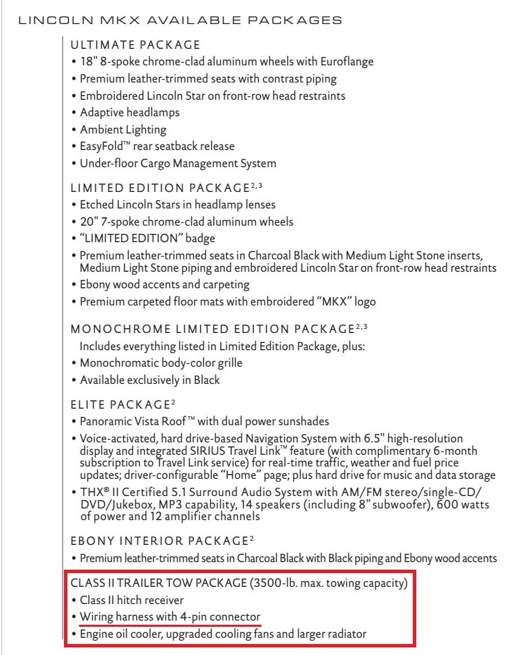
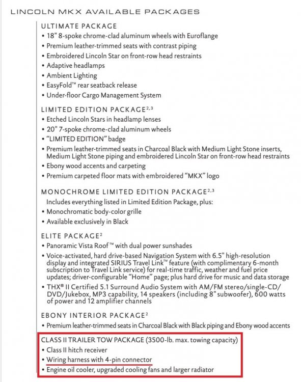
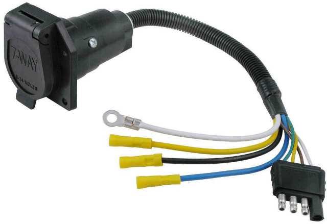
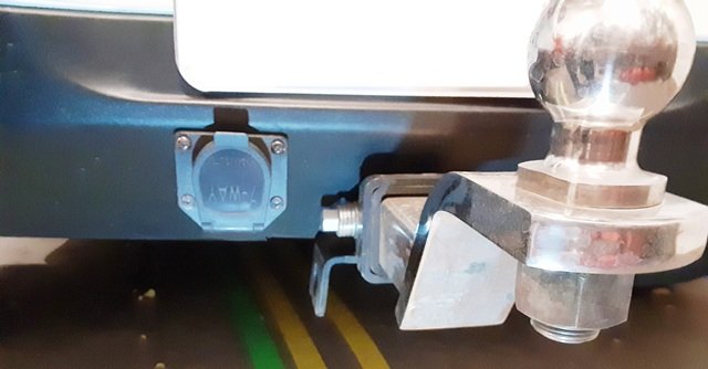
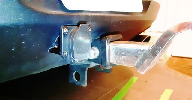
I opted to use a 7-way receptacle that has a 4-way connector and pigtails for the remaining three circuits... ...mounted into the matte black lower bumper cover of our 2015 MKX... ...using rigid nylon tubing on the lower screws to standoff the bottom flange from the angled bumper cover face... I decided to orient the flap's spring-loaded hinge on the bottom for improved visibility when inserting the boat trailer plug. Good luck!
-
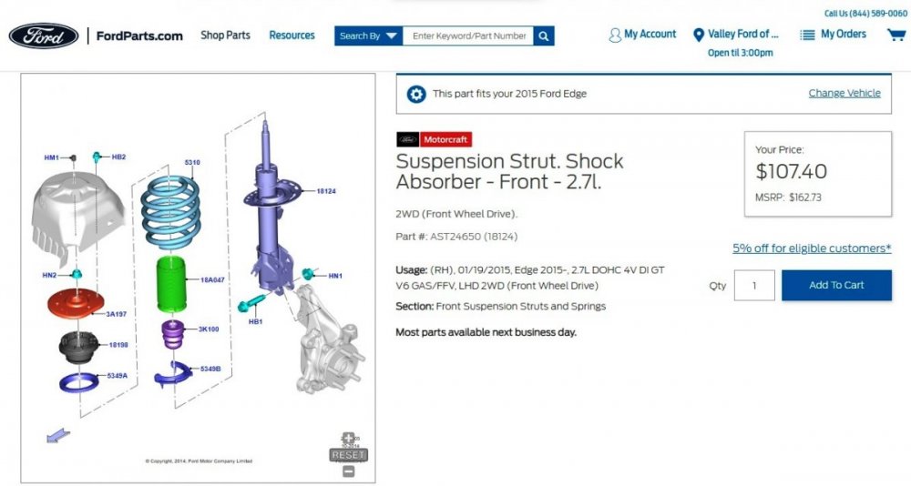
2015 Ford Edge Sport w/21” wheels FWD OEM Strut part number
Haz replied to jdawg21's topic in Brakes, Chassis & Suspension
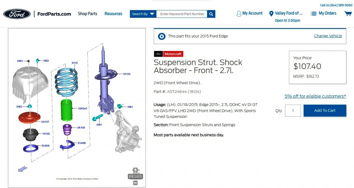
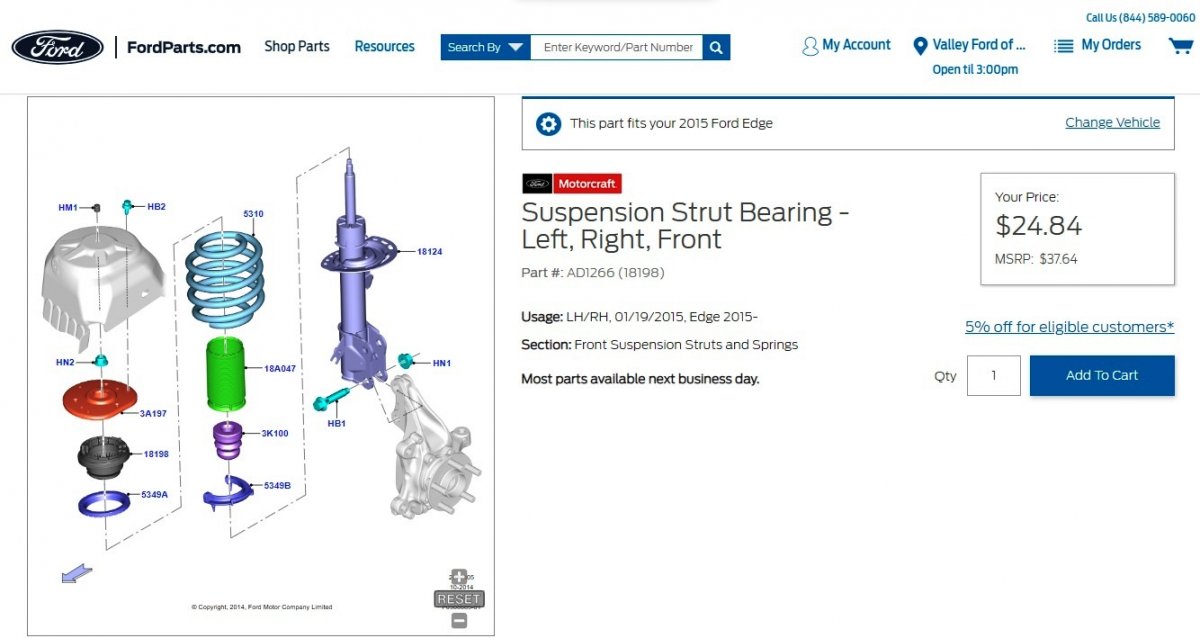
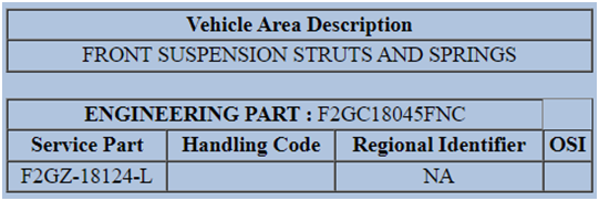
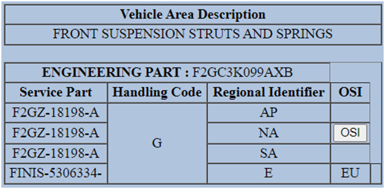
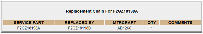
The following part numbers are from your Edge's VIN-specific Historic Vehicle Bill of Material (HVBoM) Report, with the originally installed Ford component being the Engineering Part, the contemporary replacement Ford component being the Service Part, along with the Motorcraft part number, cross-checked on Ford's parts website using your Edge's VIN ... Left Hand Strut Shock Absorber Motorcraft Part Number: AST24644 FordParts.com page link Right Hand Strut Shock Absorber Motorcraft Part Number: AST24650 FordParts.com page link Left Hand & Right Hand Strut Bearings FordParts.com page link Good luck!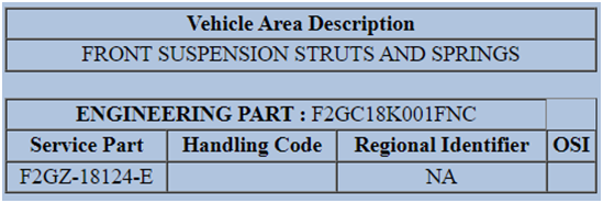


-
Confirming availability at a surprisingly low cost, though lack of mechanical override in event of transmitter failure would worry me. No cats were harmed during the course of my research. Good luck!
-
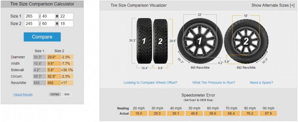
Wheel-Size.com provides original equipment wheel & tire dimensional information on Ford Edge by model year. Some Mustang rims are also said to be dimensionally Edge-compatible. TireSize.com allows comparison of two tire/wheel size combinations to determine if speedometer error is created by the proposed change. Car-Part.com allows easy searching of auto salvage yards for used wheels, providing price, grading of condition/appearance, and usually photos of wheels available for purchase. My personal experience of swapping 265/40R22 tires on factory rims with 245/60R18 tires on factory rims between 2012 & 2015 MKXs did induce speedometer error in each vehicle that was easily corrected using Forscan. Good luck!
-
Service Advancetrac light on 2012 Edge while in idle
Haz replied to 2012 Edge's topic in 2012 Edge & MKX
PDF download link... TSB 13-1-15 - ABS-AdvancedTrac Warning Light Illuminated - 2011-2013 Edge-MKX Built on or before 01-23-2013.pdf Good luck! -
Original ALERT Announcement - 2021 Edge - Sirius Radio Inoperative After APIM Update - October 17, 2022 Certain 2021 Edge vehicles which have received an APIM software update may experience a concern with Sirius radio being inoperative. This will be accompanied by audio control module (ACM) DTC B1A89:13 for the satellite antenna. Engineering is investigating this concern. Monitor PTS for updates.
-
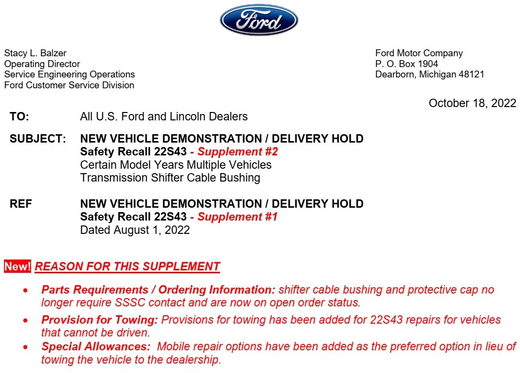
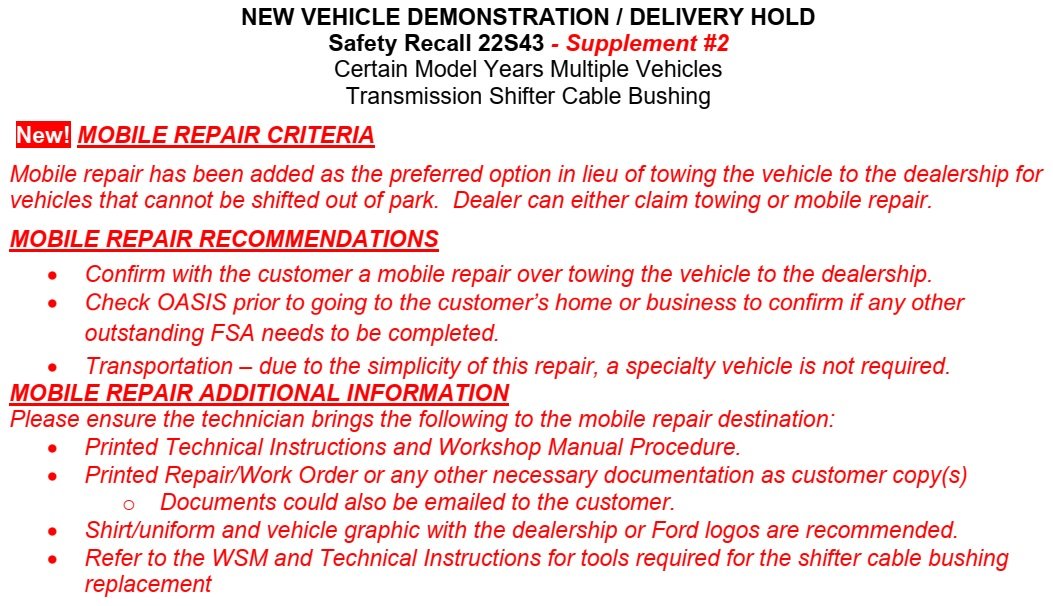
Mobile repair service conducted at owner's home or business, and towing of undriveable vehicle being added to Safety Recall 22S43... Good luck!


-
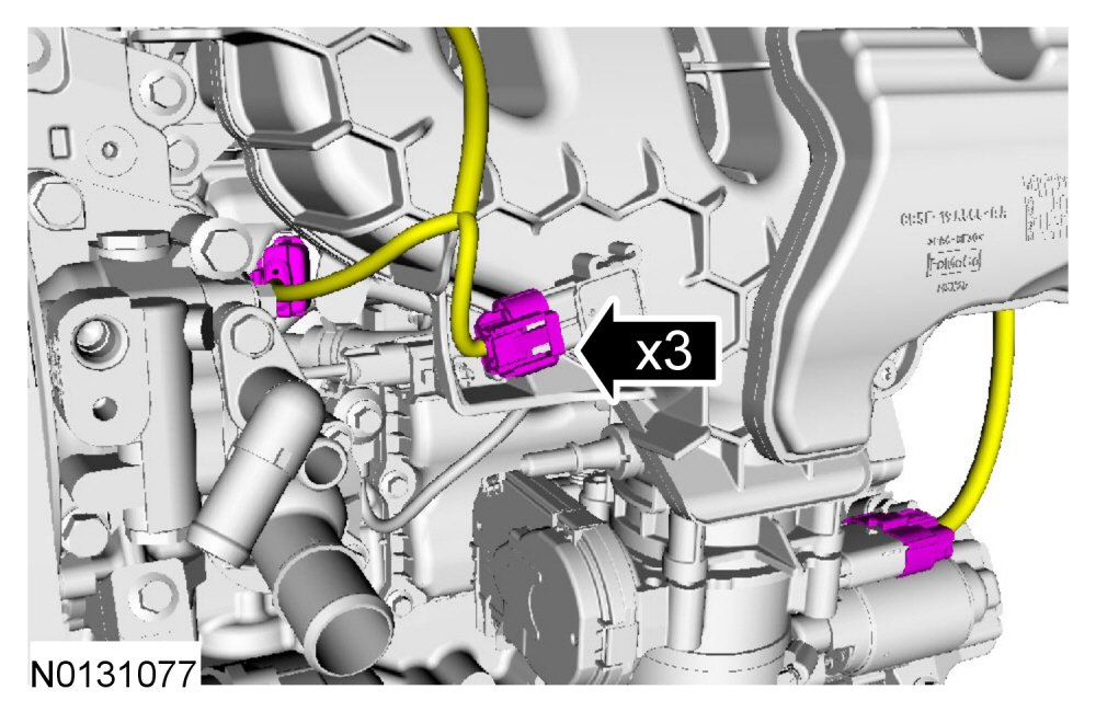
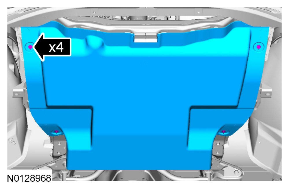
Relevant sections from the 2013 Edge Workshop Manual presented below as PDF download links to guide your efforts: Valve Cover - 2.0L EcoBoost - In-Vehicle Repair - 2013 Edge Workshop Manual.pdf , which includes these two images in reduced format, enlarged here for clarity... Loosen-Install the 4 retainers and remove-install the underbody shield - Illustration - 2013 Edge Workshop Manual Disconnect-Connect the FRP sensor, the MAP sensor and fuel charge harness electrical connectors - Illustration - 2013 Edge Workshop Manual Intake Air System Components — Exploded View - 2.0L EcoBoost - Removal and Installation - 2013 Edge Workshop Manual.pdf Ignition Coil-On-Plug - Removal And Installation - 2013 Edge Workshop Manual.pdf Quick Connect Coupling - General Procedures - 2013 Edge Workshop Manual.pdf Good luck!
-
This bulletin supersedes 19-2332. Model: Ford 2015-2017 Edge Engine: 2.7L 2017 Fusion Engine: 2.7L Lincoln 2017 Continental Engine: 2.7L Engine: 3.0L 2016-2017 MKX Engine: 2.7L 2017 MKZ Engine: 3.0L Summary This article supersedes TSB 19-2332 to update the part list. Issue: Some 2015-2017 Edge, 2016-2017 MKX, 2017 Fusion/MKZ/Continental vehicles equipped with a 2.7L EcoBoost or 3.0L EcoBoost engine vehicles may exhibit an oil leak from the engine oil pan RTV seal. This may be due to a lack of RTV adhesion. This article includes detailed steps to achieve proper RTV adhesion. To correct the condition, follow the Service Procedure steps to replace the oil pan. Action: Follow the Service Procedure steps to correct the condition on vehicles that meet all of the following criteria: Parts Service Part Number Quantity Description Unit of Issue Piece Quantity KU2Z-6731-A 1 Oil Filter Element And O-Ring Seals 1 1 9W7Z-19B596-A 1 Seal Kit - A/C Compressor Gasket And O-Ring, 1/2 Inch (Edge/MKX) 1 1 DL3Z-19B596-B 1 Seal Kit - A/C Compressor Gasket And O-Ring, 5/8 Inch (Continental 2.7L) 1 1 DS7Z-19B596-A 1 Seal Kit - A/C Compressor Gaskets 8 mm, 1/2 Inch, 5/8 Inch (All Models) 1 1 HL3Z-19B596-A 1 Seal Kit - A/C O-Rings - 3/4 Inch, 1/2 Inch, 5/8 Inch And 3/8 Inch (Fusion/MKZ And Continental 3.0L) 1 1 W714265-S442 1 Left Catalytic Converter Nuts 4 2 BL3Z-9450-A 1 Catalytic Converter Gasket 1 1 FT4Z-6626-A 1 Oil Pump Seal 1 1 FT4Z-6675-C 1 Oil Pan 1 1 ZC-30-A As Needed Motorcraft® Gasket Remover ZC-31-B As Needed Motorcraft® Metal Surface Prep Wipes TA-357 As Needed Motorcraft® High Performance Engine RTV Silicone XO-5W30-Q1SP As Needed Motorcraft® SAE 5W-30 Synthetic Blend Motor Oil (All Markets Except Canada) CXO-5W30-LSP6 As Needed Motorcraft® SAE 5W-30 Super Premium Motor Oil (Canada Only) PM-4-A As Needed Motorcraft® Metal Brake Parts Cleaner (Compliant With Low Volatile Organic Compound Requirements As Required In Some USA States) PM-4-B As Needed Motorcraft® Metal Brake Parts Cleaner (Not Compliant With Volatile Organic Compound Requirements) ZC-20 As Needed Motorcraft® Engine Shampoo and Degreaser (All Markets Except Canada) CXC-66-A As Needed Motorcraft® Engine Shampoo (Canada Only) Parts Parts To Inspect And Replace Only If Necessary Service Part Number Quantity Description FT4Z-6A832-C If Needed Oil Filter And Cap Assembly Kit Quantity refers to the amount of the service part number required to repair the vehicle. Unit of Issue refers to the number of individual pieces included in a service part number package. Piece Quantity refers to the total number of individual pieces required to repair the vehicle. As Needed indicates the amount of the part may vary and/or is not a whole number. Parts can be billed out as non-whole numbers, including less than 1. If Needed indicates the part is not mandatory. Warranty Status: Eligible under provisions of New Vehicle Limited Warranty (NVLW)/Service Part Warranty (SPW)/Special Service Part (SSP)/Extended Service Plan (ESP) coverage. Limits/policies/prior approvals are not altered by a TSB. NVLW/SPW/SSP/ESP coverage limits are determined by the identified causal part and verified using the OASIS part coverage tool. Labor Times Description Operation No. Time 2017 Continental 2.7L/3.0L EcoBoost: Inspect And Replace The Engine Oil Pan (Do Not Use With Any Labor Operations Outside Of This Article) (Can Be Claimed With D Or E And F) 222181A 3.2 Hrs. 2015-2017 Edge, 2016-2017 MKX 2.7L EcoBoost: Inspect And Replace The Engine Oil Pan (Do Not Use With Any Labor Operations Outside Of This Article) (Can Be Claimed With D Or E And F) 222181B 3.5 Hrs. 2017 Fusion 2.7L EcoBoost, 2017 MKZ 3.0L EcoBoost: Inspect And Replace The Engine Oil Pan (Do Not Use With Any Labor Operations Outside Of This Article) (Can Be Claimed With D Or E And F) 222181C 3.4 Hrs. 2015-2017 Edge, 2016-2017 MKX, 2017 Continental/Fusion/MKZ: Additional Time To Check And Correct Toe Vehicles Without Lane Departure 222181D 0.6 Hrs. 2015-2017 Edge, 2016-2017 MKX, 2017 Continental/Fusion/MKZ: Additional Time To Check And Correct Toe Vehicles With Lane Departure 222181E 0.8 Hrs. 2015-2017 Edge, 2016-2017 MKX, 2017 Continental/Fusion/MKZ: Additional Time When 360 Degree Camera Alignment Is Necessary 222181F 0.5 Hrs. Repair/Claim Coding Causal Part: 6675 Condition Code: D8 Service Procedure CAUTION: 2015-2017 model year vehicles are not compatible with the press-in-place gasket oil pan. Installation of the press-in-place gasket oil pan results in engine damage. 1. Remove and discard the oil pan and oil pump seal. It is recommended to allow the crankcase to drain overnight to prevent contamination of the engine sealing surface. Refer to the Workshop Manual (WSM), Section 303-01. NOTE: Cleaning and preparation of the engine sealing surface is critical for proper adhesion of the new oil pan. Improperly cleaned and prepared sealing surfaces results in an oil leak. 2. Thoroughly clean the engine sealing surface using Motorcraft® Silicone Gasket Remover and a plastic scraper. Allow the gasket remover to set for several minutes after application to aid in removal of the RTV sealant. (1). The engine block skirt stiffener sealing surface must be clean and free of any residual RTV. Do not use metal scrapers, wire brushes, or rotary tools of any type on the engine sealing surface. These tools damage the sealing surface including scratches or gouges that create leak paths. A second application of Motorcraft® Silicone Gasket Remover may be required. NOTE: When cleaning the engine sealing surface it must be wiped clean using a lint free cloth. Spraying the surface with brake cleaner and air drying does not adequately remove the oil and other contaminates from the surface and may leave residue from the brake cleaner that may interfere with RTV adhesion. 3. Use a lint free towel and Motorcraft® Metal Brake Parts Cleaner to remove all residual sealant and oil from the engine sealing surface until a clean lint free towel no longer shows any residual oil when wiping the surface. (Figures 1-2) (1). Use only Motorcraft® Metal Brake Parts Cleaner to clean the engine sealing surface. Some unapproved brake parts cleaners contain chemicals that inhibit RTV adhesion or may evaporate without removing all of the residual oil from the sealing surface resulting in a repeat leak condition. Figure 1 Figure 2 NOTE: Motorcraft® Engine Shampoo and Degreaser removes residual brake cleaner which can cause RTV failure and prepares the surface for the Motorcraft® Metal Surface Prep Wipes. The use of any other brand engine shampoo or engine cleaner can compromise the sealing surface and lead to failure of the RTV seal and a fluid leak. 4. Use Motorcraft® Engine Shampoo and Degreaser to clean the surface of any remaining oil contamination and prepare the surface for the Motorcraft® Metal Surface Prep Wipes. Dry the surface with a lint free towel. NOTE: Do not use Motorcraft® Metal Surface Prep Wipes on the replacement oil pan. Using Motorcraft® Metal Surface Prep Wipes on the oil pan contaminates the treated oil pan sealing surface causing reduced RTV adhesion and a potential oil leak. 5. Wipe the metal engine block skirt stiffener sealing surface using Motorcraft® Metal Surface Prep Wipes. Thoroughly coat the surface with the fluid. Discard the wipes after a single use. (1). Motorcraft® Metal Surface Prep Wipes create a conversion coating providing an improved base for RTV sealing. The wipes use a water-based, slightly acidic solution that etches and bonds to the metal providing a microscopic layer for the RTV to adhere to. If the surface is oily, the solution beads and the surface is not properly treated. If the solution beads when applied to the sealing surface, clean the surface again and reapply the Motorcraft® Metal Surface Prep Wipes. (Figures 3-4) NOTE: If the sealing surface or an area of the sealing surface becomes contaminated after it has been prepared, use a lint-free towel soaked in isopropyl alcohol to clean the area. Prepare the area again using Motorcraft® Metal Surface Prep Wipes. Figure 3 Figure 4 6. Allow the surface to air dry for approximately 2 minutes. (1). Do not dry the surface using any other method. Attempting to dry the surface may result in sealing surface contamination that may cause oil leaks. 7. Install the new oil pump seal. Refer to the WSM, Section 303-01. NOTE: The oil pan must be installed within 10 minutes of applying the RTV. 8. Apply a 4.5 mm (0.18 in) bead of Motorcraft® High Performance Engine RTV Silicone to the new oil pan. The RTV bead must be applied to straddle the step chamfer and sealing face. (Figures 5-6) (1). Using too little sealant may result in oil leaks and using too much sealant may result in oil contamination and engine damage. Figure 5 Figure 6 9. Apply a 9 mm (0.35 in) bead of Motorcraft® High Performance Engine RTV Silicone to the engine front cover-to-cylinder block joint areas on the new oil pan as shown in Figure 5. 10. Install the new oil pan. Refer to the WSM, Section 303-01. PDF download link... TSB 22-2181 - 2015-2017 Edge 2.7L EcoBoost, 2016-2018 MKX 2.7L EcoBoost + Other Models - Oil Pan Leaking.pdf Good luck!
-
2016 Edge - A/C water Drain location?
Haz replied to omar302's topic in Interior, A.C., Heat, Interior Trim
For the sake of continuity, I checked the 2015 North American Edge Workshop Manual for "Hot Market" and was presented the Engine Cooling diagrams you shared. Next I accessed the 6F50-6F55 Transmission Cooling section, and the documents I shared are also in the 2015 Workshop Manual. I join you in believing the warmer/cooler component is the same in each category of Engine Cooling & Transmission cooling context, given this description I didn't previously include... Transmission Cooling - Overview The transmission fluid cooling system consists of the following: An oil-to-air transmission fluid cooler integrated with the A/C condenser A transmission fluid cooler bypass valve If equipped, a transmission fluid warmer Tubes to all fluid to flow to the various components The transmission fluid flows from the transmission to the cooler bypass valve. When the transmission fluid is below normal operating temperature, the bypass valve directs the flow back to the transmission. When the transmission fluid is at or above normal operating temperature, the bypass valve directs the flow through the transmission fluid cooler, which transfers heat from the fluid to the air passing over the cooler. The transmission fluid then returns to the transmission. The transmission fluid warmer optimized transmission fluid temperature. The transmission fluid warmer transfers heat either from the coolant to the transmission fluid or from the transmission fluid to the coolant. If equipped, the transmission fluid flows through the warmer. When the coolant is warmer than the transmission fluid, heat is transferred from the coolant to the transmission fluid, warming the transmission fluid quickly to improve efficiency. When the transmission fluid is warmer than the coolant, heat is transferred from the transmission fluid to the coolant, providing additional transmission fluid cooling. As I prepared to upgrade the engine & trans cooling on our 2015 MKX to Tow Package capability, the tow package radiator was also characterized as being part of the high ambient temperature package, presumably the Hot Market spec. I had them install an aftermarket transmission fluid cooler in front of the AC condenser to supplement the condenser's dual AC/trans fluid cooling role. Thanks for the document you shared and good luck! -
2016 Edge - A/C water Drain location?
Haz replied to omar302's topic in Interior, A.C., Heat, Interior Trim
Two references on your bonus-pictured transmission fluid warmer/cooler from the 2016 Edge Workshop Manual... 6F50-6F55 Active Warmup Cooling Diagram - 2016 Edge Middle East-Qatar Workshop Manual .pdf Transmission Fluid Warmer R & I - 2.7L EB & 3.5L TiVCT - 6F50-6F55 6-Speed Transmission - 2016 Edge Workshop Manual.pdf Good luck! -
From the 2010 Gasoline Engine Powertrain Control/Emissions Diagnosis (PC/ED) Manual, with emphasis added... Engine RPM And Vehicle Speed Limiter The PCM disables some or all of the fuel injectors whenever an engine RPM or vehicle over speed condition is detected. The purpose of the engine RPM or vehicle speed limiter is to prevent damage to the powertrain. When the vehicle exhibits a rough running engine condition, the PCM stores one of the following continuous memory diagnostic trouble codes (DTCs): P0219, P0297, or P1270. Once the driver reduces the excessive speed, the engine returns to the normal operating mode. No repair is required. However, the technician should clear the DTCs and inform the customer of the reason for the DTC. Excessive wheel slippage may be caused by sand, gravel, rain, mud, snow, ice, or excessive and sudden increase in RPM while in NEUTRAL or while driving. Good luck!
-
Wheel-Size.com's Ford Edge pages Good luck!
-
No Oasis announcement today, so perhaps this is an ingenious owner-developed workaround toward interim front camera functionality. Still looking for a bagel emoji to more properly award @Ford Fanatic 28's analysis of the method. Good luck!
-
Welcome to the Forum, and no regrets are necessary when you're being a good son. Best to get the battery tested to ensure it it doesn't have a bad cell, since tender age does not guarantee a trouble-free battery. Multiple communications DTCs often occur from a failing or failed battery's low voltage output. If you do replace the current battery with new, you may already be aware of this advice from the 2014 Edge Workshop Manual... NOTE: When the battery (or PCM) is disconnected and connected, some abnormal drive symptoms may occur while the vehicle relearns its adaptive strategy. The charging system set point may also vary. The vehicle may need to be driven to relearn its strategy. Carry out the Battery Monitoring System (BMS) Reset using the scan tool after the battery is connected. If the BMS Reset is not carried out, it takes approximately 8 hours for the Body Control Module (BCM) to learn the new battery state of charge. During this 8 hour period, the vehicle must be undisturbed, with no doors opened or keyless entry button presses. If the vehicle is used before the BCM is allowed to learn the new battery state of charge, engine off load shedding can still occur and a message may be displayed. Good luck!