Haz
-
Posts
1,568 -
Joined
-
Last visited
-
Days Won
439
Content Type
Profiles
Forums
Gallery
Everything posted by Haz
-
Welcome to the Forum! Document download links> Body Control Module (BCM) - Diagnosis and Testing - 2014 Edge Workshop Manual.pdf Body Control Module (BCM) - Removal and Installation - 2014 Edge Workshop Manual.pdf If your Edge is disabled and you need to get it back on the road, locating an A-graded used Body Control Module (BCM) from a local Salvage Yard at 25%-to-50% of the new part cost using the Car-Part.com search engine may be worthwhile... Good luck!

-FordParts.thumb.jpg.c31fd72e77a14a7f60ec91e00c1929b2.jpg)
-
Fluttering Noise from Undercarriage and Dashboad Rattle
Haz replied to CCMAYES72's topic in Brakes, Chassis & Suspension
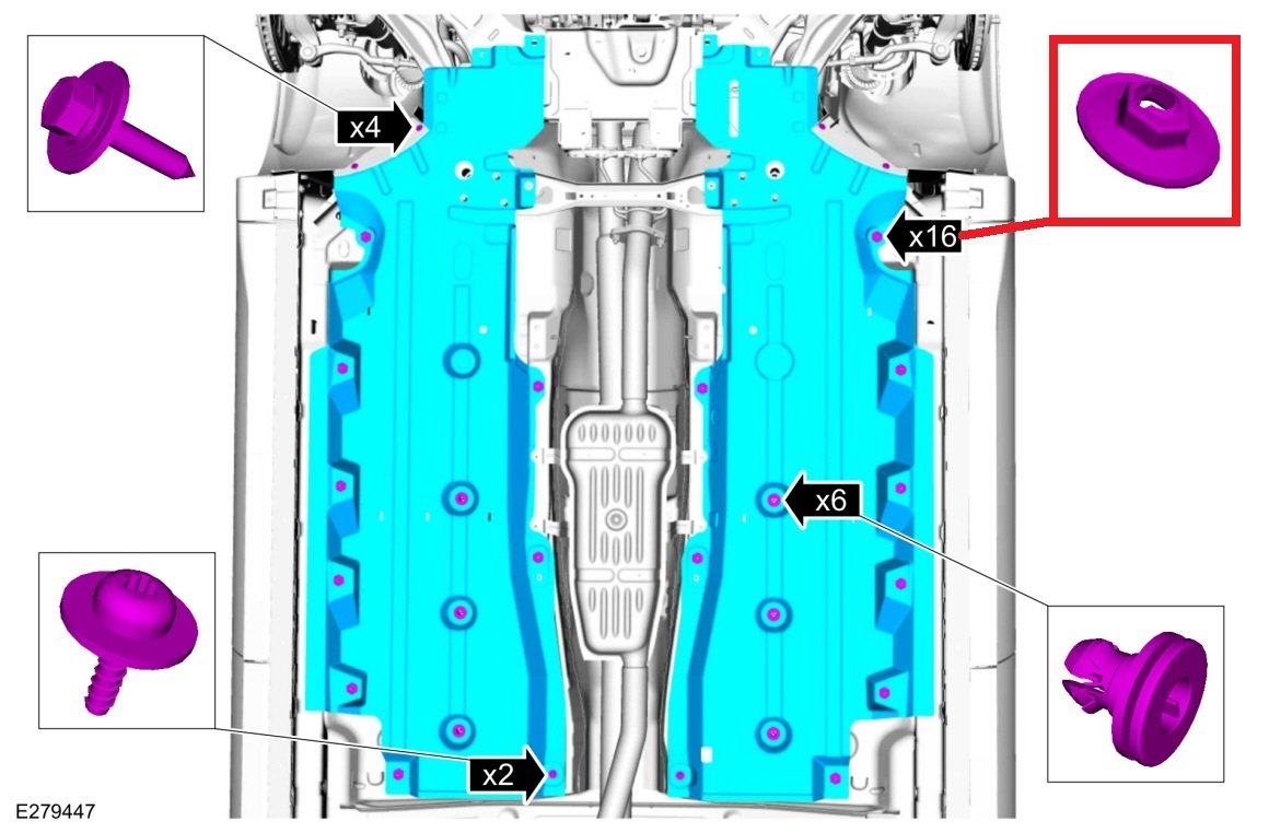
From the 2019 Edge Workshop Manual... The stamped sheet metal hex nut is also described online as a speed nut. I was unable to pick off the fastener part number from FordParts.com, though a dealership parts staffer will likely find it. On the other hand, providing 1004ron's photo to a local or national-brand auto parts store or hardware store may provide the part quicker and cheaper. Good luck!
- 91 replies
-
- 1
-

-
- dash noise
- dash rattle
- (and 4 more)
-
The 2022 Edge Workshop Manual offers this Auto-Start-Stop operational description and lists the conditions under which Auto-Start-Stop will not function... Auto-Start-Stop System The Auto-start-stop system helps reduce fuel consumption by automatically shutting off the vehicle’s engine while the vehicle is at a complete stop and restarting the engine when the brake pedal is released. The system can be disabled through the auto-start-stop control switch on the instrument panel centerstack. The Auto-start-stop system is automatically enabled whenever the ignition is turned on. The engine automatically restarts when: the brake pedal is released. the Auto-start-stop system is disabled through the auto-start-stop control switch on the instrument panel centerstack. the battery has a low state of charge. it is necessary to maintain interior comfort. the blower fan speed is increased or the climate control temperature is changed. an electrical accessory is turned on or plugged in. there is low brake vacuum. The Auto-start-stop system may not turn the engine off under these conditions: the HVAC system is in A/C, heat or defrost modes. the rear defroster is on. the battery has a low state of charge. the battery temperature is below 5°C (41°F) or above 60°C (140°F). the engine temperature is below 46°C (115°F). the engine temperature is below 60°C (140°F) and the HVAC system is in heat mode. the gear selector is not in Drive or Sport Mode. the steering wheel is turned rapidly or is at a sharp angle. vehicle speed of greater than 4 km/h (2.5 mph) for more than 2 seconds has not occurred. the vehicle is on a steep road grade. elevation is approximately above 3,048 meters (10,000 feet). Good luck!
-
Welcome to the Forum, Skipper96. Parasitic battery drain diagnostic reference... Document download link> Parasitic Battery Drain Job Aid.pdf Good luck!
-
Because your Edge is exhibiting several Power Liftgate symptoms -- change in open/close velocity; a sporadic failure to pulldown and/or latch; cargo area pushbutton opens but does not close while exterior pushbutton performs normally -- the best-first step may be to perform the Power Liftgate Initialization procedure, which involves de-powering the Rear Gate Trunk Module (RGTM)... Document download link> Power Liftgate Initialization - 2016 Edge Workshop Manual.pdf You will notice this RGTM de-powering can be done either by pulling the RGTM fuses or by disconnecting the Edge's battery. If you choose pulling fuses, there are two -- F76 in the Battery Junction Box (BJB) and F10 in the Body Control Module (BCM)... Battery Junction Box (BJB) Images Release the tabs. Lift and position the top part of the junction box aside. Body Control Module (BCM) Images de-powering Be aware that the alternative RGTM de-powering method -- Battery Disconnect procedure -- offers these cautions... NOTICE: Removing the negative battery ground cable at the LH strut tower will not disable the vehicle's electrical system. Failure to disconnect the battery cable from the battery post may cause component damage. NOTE: When the battery is disconnected and connected, some abnormal drive symptoms may occur while the vehicle relearns its adaptive strategy. The vehicle may need to be driven to allow the PCM to relearn the adaptive strategy values. Document download link> Battery Disconnect and Connect - General Procedures - 2016 Edge Workshop Manual.pdf The following Workshop Manual section provides a wonderful explanation of Power Liftgate operation in conjunction with the RGTM and other components... Document download link> Power Liftgate System - Description and Operation - 2016 Edge Workshop Manual.pdf Please report back on the outcome of the Power Liftgate Initialization procedure. Good luck!
PowerSourceWiringDiagramHighlighted-2016EdgeWorkshopManual.thumb.jpg.56d64405e4caec1455edc94e14b04142.jpg)
-TopViewDiagram-2016EdgeWorkshopManual.thumb.jpg.07e573f55054557712a853c5fd2d7517.jpg)
Image1-FordPartsWebsite.thumb.jpg.4abbf3f900a0a905c5eba8f6535e3f7f.jpg)
Image2-FordPartsWebsite.thumb.jpg.c8187c0edb9ce8ab28c9fb2c05364597.jpg)
Image3-FordPartsWebsite.thumb.jpg.e5487a31eab0c4b340819be50322f858.jpg)
Image4-FordPartsWebsite.thumb.jpg.661f8ea65d450e7432420b3fdc54faea.jpg)
-BottomViewDiagramHighlighted-2016EdgeWorkshopManual.thumb.jpg.c51f8eaea7513beb56579c4be97366e3.jpg)
In-PlaceIllustration-2016EdgeWorkshopManual.jpg.f73c412529a9a93d9b0cd9be12fbaf8a.jpg)
DiagramHighlighted-2016EdgeWorkshopManual.thumb.jpg.b6cbec5b2062cebc98af421710ece700.jpg)
ImageHighlighted-FordPartsWebsite.thumb.jpg.36e98a06820d74ed2ced265c32d8bc46.jpg)
In-PlaceIllustration-2016EdgeWorkshopManual.jpg.175292f3d47024f9b7e261e7abf55351.jpg)

-
The following is a PDF document download link to the relevant section from the Edge Workshop Manual... Windshield Wiper Pivot Arm - Removal and Installation - 2022-2023 Edge Workshop Manual.pdf It includes this guidance, which the windshield installer may not have done... Installation NOTICE: The ignition switch must be set to the ON position. Power is required to hold the wiper motor in the PARK position. No power or low battery voltage will allow the motor to move from the PARK position during the torquing operation resulting in incorrect wiper arm position. Good luck!
-
Welcome to the Forum! Below are relevant sections from the 2019 Edge Workshop Manual... Document download links> Rear Spoiler - Removal and Installation - 2019 Edge Workshop Manual.pdf High Mounted Stoplamp - Removal and Installation - 2019 Edge Workshop Manual.pdf Good luck!
-
Welcome to the Forum! This Special Service Message was released on December 23, 2021... SSM 50375 2016-2021 Various Vehicles - Loss of Navigation Voice Prompts After A SYNC Map Update Some 2016-2021 Ford and Lincoln vehicles equipped with SYNC 3 may exhibit a condition where the navigation voice prompts are inoperative after a SYNC map update. This may be due to an incomplete installation of the SYNC map software. If possible, using the original USB that installed the update, reperform the update and verify the navigation voice prompts have returned. Multiple reboots are expected when this update is being performed. Verify the Installation Is Complete message displays in the touch screen. If the original USB is not available, go to website https://syncnavigation.com/ford/home or https://syncnavigation.com/lincoln/home to download the files once more for the affected vehicle. For further map update support, reference the FAQ section on these websites. Additionally, the following SYNC-related Technical Service Bulletin was released on June 2, 2021... Document download link> TSB 21-2175 - 2016-2019 Various Vehicles - SYNC 3 – Various SYNC Performance Related Concerns.pdf Good luck!
-
Welcome to the Forum! Based upon your comment that the battery won't hold a charge, you may want to have the battery tested to determine if it has a failing or failed cell(s). Low battery voltage alone will induce a myriad of Diagnostic Trouble Codes (DTCs) and electronic module symptoms, and replacing a failing/failed battery may (surprisingly) clear up many problems. Please report back on the outcome, and I'll gladly supply diagnostic procedures to address any enduring DTCs that your Edge exhibits. Good luck!
-
From the 2014 Edge-MKX Workshop Manual... Document download links> Crankshaft Rear Seal - In-Vehicle Repair - 2014 Edge-MKX Workshop Manual.pdf Crankshaft Rear Seal With Retainer Plate - In-Vehicle Repair - 2014 Edge-MKX Workshop Manual.pdf Good luck!
-
Relevant sections from the 2018 Edge Workshop Manual... Document download links> Liftgate Latch Manual Release - 2018 Edge Workshop Manual.pdf Liftgate Latch - Removal and Installation - 2018 Edge Workshop Manual.pdf Liftgate Trim Panel - Removal and Installation - 2018 Edge Workshop Manual.pdf Power Liftgate Initialization - 2018 Edge Workshop Manual.pdf Power Rear Liftgate - Diagnosis and Testing - 2018 Edge Workshop Manual.pdf Power Liftgate Wiring Diagram 1 - 2018 Edge Workshop Manual.pdf Power Liftgate Wiring Diagram 2 - 2018 Edge Workshop Manual.pdf Power Liftgate Wiring Diagram 3 - 2018 Edge Workshop Manual.pdf Power Liftgate Wiring Diagram 4 - 2018 Edge Workshop Manual.pdf Power Liftgate Wiring Diagram 5 - 2018 Edge Workshop Manual.pdf Power Rear Liftgate - Component Location - 2018 Edge Workshop Manual.pdf Power Rear Liftgate - System Operation - 2018 Edge Workshop Manual.pdf Owner comments in this past discussion should be helpful to you. Good luck!
-
Welcome to the Forum! From the 2011 Edge Workshop Manual... Instrument Cluster and Panel Illumination - Principles of Operation Dimmable Backlighting The instrument panel dimmer switch is integral to the Front Lighting Control Module (FLM) . When the parking lamps are on, the FLM sends an illumination command message to the Body Control Module (BCM) over the High Speed Controller Area Network (HS-CAN) . The BCM sends voltage to the hardwired dimmable components and switches based on the network message received from the FLM . The BCM also sends a message over the Controller Area Network (CAN) to the Instrument Panel Cluster (IPC) , the FLM and the HVAC module, to indicate the backlighting intensity level. The IPC gateways the message from the HS-CAN to the Infotainment Controller Area Network (I-CAN) to the Front Controls Interface Module (FCIM) , the Front Control/Display Interface Module (FCDIM) (if equipped), and the Accessory Protocol Interface Module (APIM) (if equipped). If equipped, the Front Display Interface Module (FDIM) is attached to the APIM . The APIM gateways the illumination intensity level message to the FDIM . A bar graph window is displayed in the message center of the IPC indicating the backlighting intensity level. If the receiving module receives invalid backlighting data from the BCM for 5 seconds or less, the receiving module defaults the backlighting to the last setting. If the receiving module does not receive the backlighting status message from the BCM or if the data received is deemed invalid for more than 5 seconds, the receiving module sets a DTC in continuous memory and defaults the backlighting to full nighttime intensity. Non-Dimmable Backlighting (Edge only) When the accessory delay relay is energized, switched voltage is supplied to the window control and door lock control switches. Field-Effect Transistor (FET) Protection A Field-Effect Transistor (FET) is a type of transistor that, when used with module software, can be used to monitor and control current flow on module outputs. The FET protection strategy prevents module damage in the event of excessive current flow. The BCM utilizes an FET protective circuit strategy for many of its outputs (for example, a headlamp output circuit). Output loads (current level) are monitored for excessive current (typically short circuits) and are shut down (turns off the voltage or ground provided by the module) when a fault event is detected. A short circuit DTC is stored at the fault event and a cumulative counter is started. When the demand for the output is no longer present, the module resets the FET protection to allow the circuit to function. The next time the driver requests a circuit to activate that has been shut down by a previous short (FET protection) and the circuit is still shorted, the FET protection shuts off the circuit again and the cumulative counter advances. When the excessive circuit load occurs often enough, the module shuts down the output until a repair procedure is carried out. Each FET protected circuit has 3 predefined levels of short circuit tolerance based on the harmful effect of each circuit fault on the FET and the ability of the FET to withstand it. A module lifetime level of fault events is established based upon the durability of the FET . If the total tolerance level is determined to be 600 fault events, the 3 predefined levels would be 200, 400 and 600 fault events. When each tolerance level is reached, the short circuit DTC that was stored on the first failure cannot be cleared by the clear the continuous DTCs command. The module does not allow this code to be cleared or the circuit restored to normal operation until a successful self-test proves the fault has been repaired. After the self-test has successfully completed (no on-demand DTCs present), DTC U1000:00 and the associated DTC (the DTC related to the shorted circuit) automatically clears and the circuit function returns. When each level is reached, the DTC associated with the short circuit sets along with DTC U1000:00. These DTCs are cleared using the module on-demand self-test, then the Clear DTC operation on the scan tool (if the on-demand test shows the fault corrected). The module never resets the fault event counter to zero and continues to advance the fault event counter as short circuit fault events occur. If the number of short circuit fault events reach the third level, then DTCs U1000:00 and U3000:49 set along with the associated short circuit DTC. DTC U3000:49 cannot be cleared and the module must be replaced after the repair. The BCM FET protected output circuit for the instrument cluster and panel illumination system is the dimmable switch output circuit. Document download link> Instrument Cluster and Panel Illumination - Diagnostics and Testing - 2011 Edge Workshop Manual.pdf And, just in case it is the Information and Entertainment Control Panel you're referring to... Document download link> Bezel Diagnostics - Information and Entertainment Systems General Procedures - 2011 Edge Workshop Manual.pdf And, just in case it is the SYNC System you're referring to... Document download link> Accessory Protocol Interface Module (APIM) Reset - Information and Entertainment Systems General Procedures - 2011 Edge Workshop Manual.pdf Good luck!
-
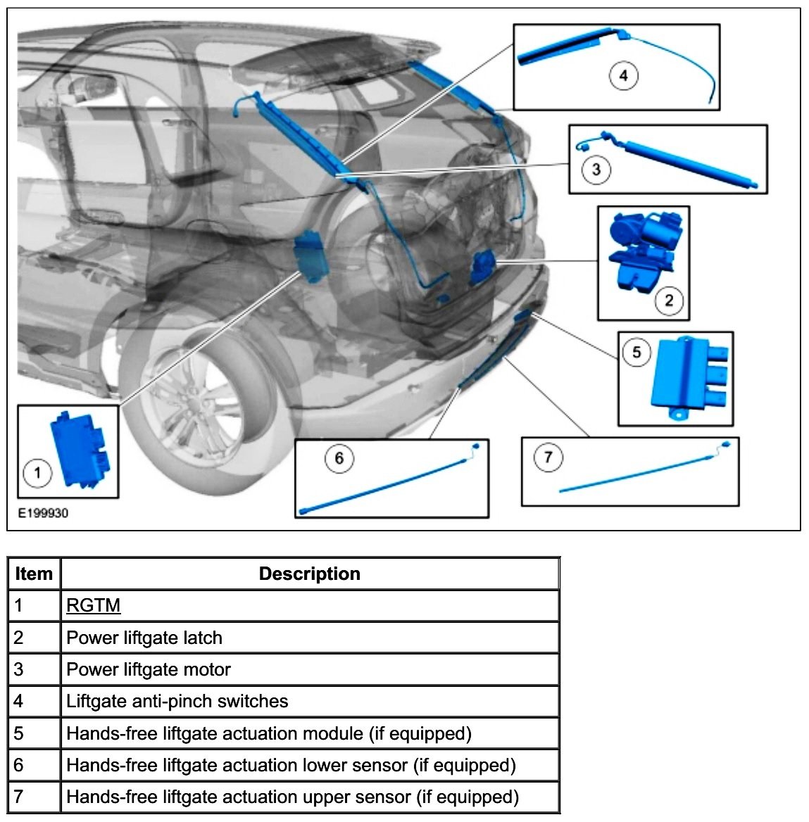
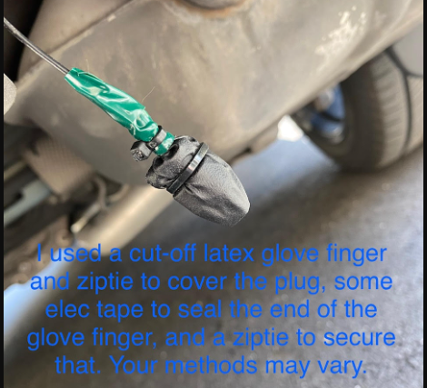
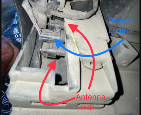
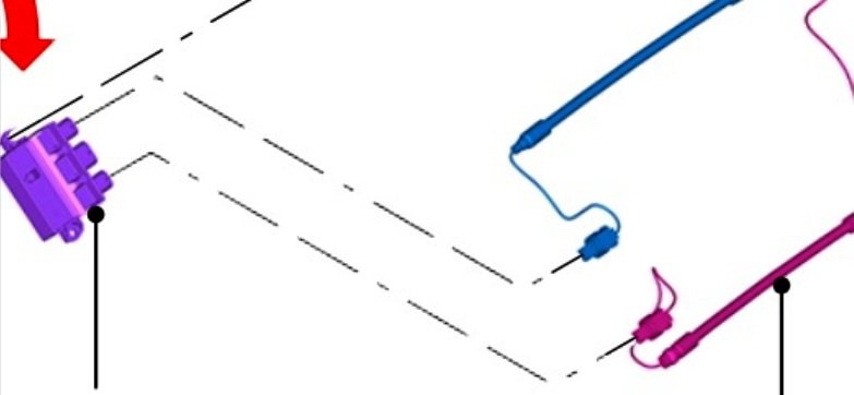
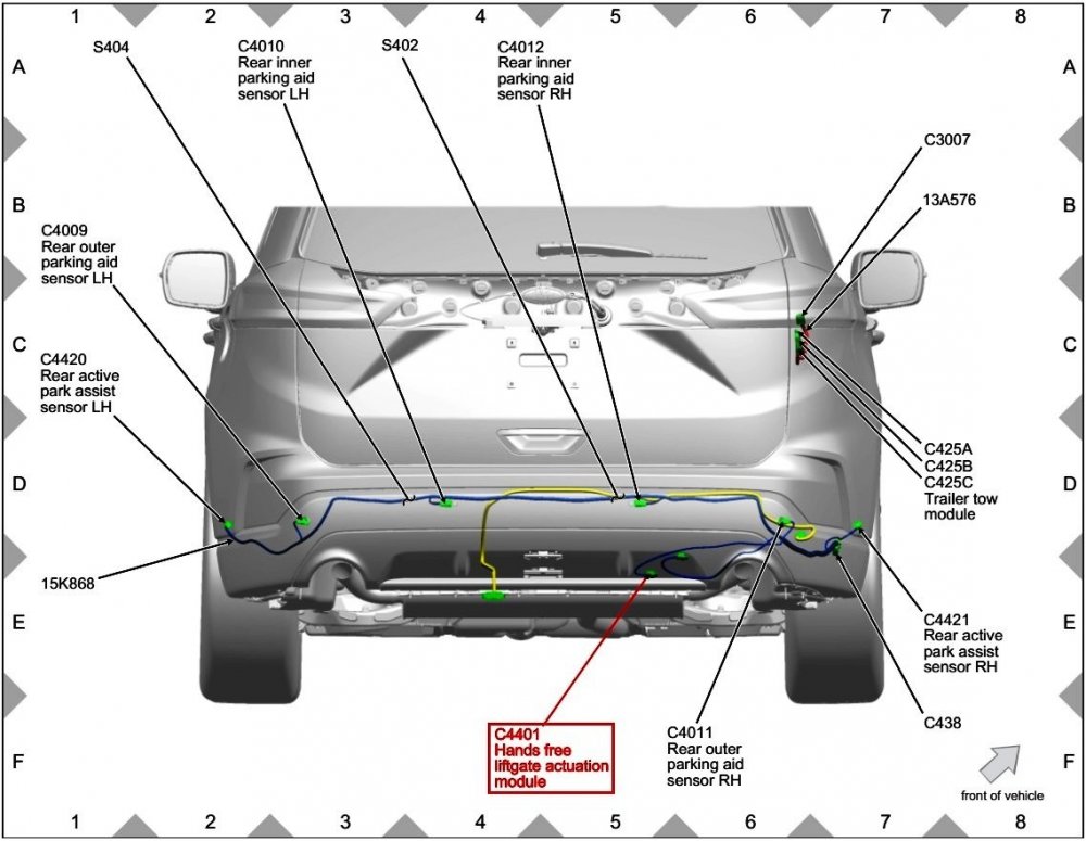
From the 2020 Edge Workshop Manual... Hands-Free Liftgate Actuation Module The hands-free liftgate actuation module is located behind the rear bumper cover on the right side of the vehicle. The hands-free liftgate actuation module receives a 12-volt signal from the BCM while monitoring 2 capacitive sensors. When the correct motion is detected from the upper and lower sensors, the hands-free liftgate actuation module momentarily grounds the voltage signal from the BCM . Hands-Free Liftgate Actuation Sensors The hands-free liftgate actuation sensors are capacitive sensors and generate capacitive fields near the rear bumper. The capacitive fields are disrupted when an object (such as a leg) enters the area. The hands-free liftgate actuation module uses this information to interpret movement near the rear bumper. In the above-linked Explorer ST Forum discussion, the Explorer owner uses the term 'Antenna Loop' to describe his vehicle's two separate Hands-Free Liftgate Actuation Sensors... Photo courtesy of KNTRDR ...which are mounted forward of the trailer hitch assembly in an upper-and-lower arrangement that is functionally identical to the two Sensors mounted on the inside of the Edge's rear bumper cover... Explorer Lower Hands-Free Liftgate Actuation Sensor Explorer Upper Hands-Free Liftgate Actuation Sensor The Explorer owner's direction is to disconnect the Upper Sensor and to leave the Lower Sensor plugged into the Hands-Free Liftgate Actuation Module, and there are no subsequent comments in that discussion saying the Hands-Free function continued to work after disconnecting the one Sensor. Looking to the Edge Workshop Manual description, the Module presumably compares electrical values generated from each Sensor and interprets simultaneous changes in the two Sensor inputs as the owner's leg sweep, which when the Intelligent Access key fob is within 3-feet of the Liftgate, triggers a power-open result (as long as the Power Liftgate is not deactivated via the Instrument Panel settings menu). So, disconnecting one Sensor may sufficient to prevent the Module from recognizing an underbody leg sweep, by eliminating the second Sensor's electrical input from comparison by the Module to the other connected Sensor's input. Unfortunately, the Hands-Free feature wasn't offered on our 2015 MKX, so I cannot personally test the difference between disconnecting one Sensor versus disconnecting both Sensors from the Hands-Free Liftgate Actuation Module. The Explorer owner's recommendation to use vinyl/nitrile gloves' cutoff finger sections zip-tied to an unused connector or module receptacle for protection from water intrusion and road dirt is a great idea that I will surely use in the future... Photo courtesy of KNTRDR Good luck!
-
Also -- Welcome to the Forum! Good luck!
-
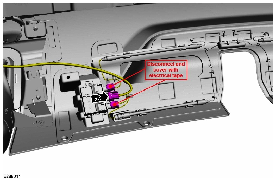
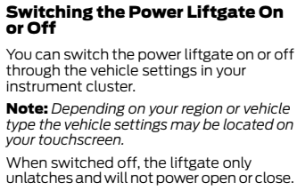
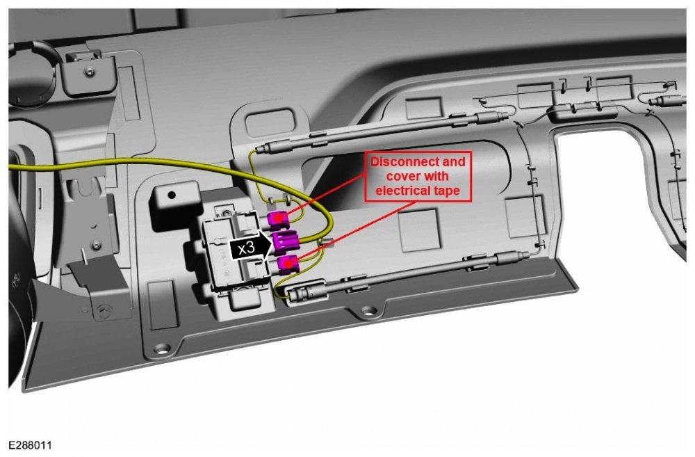
The 2022 Edge Owner's Manual, on page 83, describes deactivating the Power Liftgate raise-lower function, but makes no mention of deactivating the Hands-Free Sensors... Disconnecting the upper & lower sensors' two electrical connectors from the Hands-Free Liftgate Actuation Module, located inside the rear bumper cover toward the passenger side, will fully deactivate the Hands-Free Liftgate function... Once removed, wrap the connectors and vacant Module receptacles with electrical tape to protect them from moisture intrusion and road debris, just in case at some later date, you or a future owner wishes to restore the Hands-Free function. Good luck!
-
For a fuller understanding of how misfire events are recognized, evaluated, and reacted to by electronic engine controls -- technical, but eye-opening... Document download link> Misfire Monitor - OBD Operation Summary for Gasoline Engines - 2016 Model Year.pdf Good luck!
-
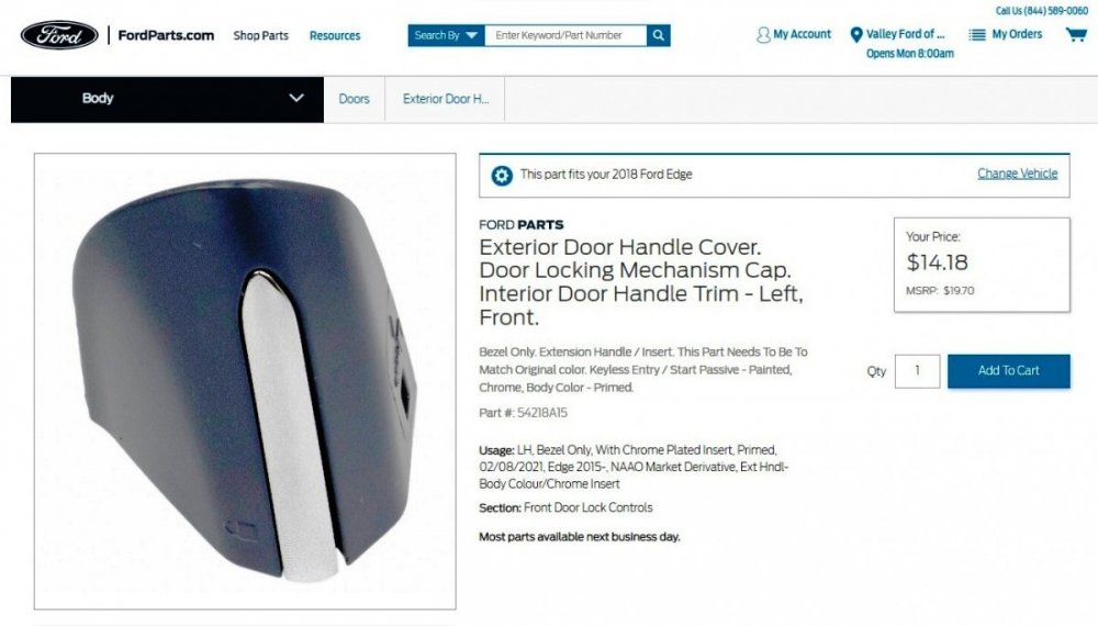
Part # 54218A15 - Exterior Door Handle Cover, Door Locking Mechanism Cap via Ford's online parts site (webpage link)... Good luck!
-
Below as PDF document download links are relevant sections from the 2016 Gasoline Powertrain Control / Emissions Diagnosis (PC/ED) Manual, and PCM Connector details from 2016 Edge Workshop Manual... Document download links> POWERTRAIN CONTROL MODULE (PCM) DTC P0301 Description-Action - 2016 2.0L EcoBoost - PC-ED Manual.pdf PINPOINT TEST HD - MISFIRE DETECTION MONITOR - 2016 2.0L EcoBoost - PC-ED Manual.pdf PINPOINT TEST Z - INTERMITTENT - 2016 2.0L EcoBoost - PC-ED Manual.pdf OBDII Freeze Frame Data - 2.0L Ecoboost - 2016 PC-ED Manual.pdf Reference Values - 2.0L Ecoboost - Section 6 - 2016 PC-ED Manual.pdf POWERTRAIN CONTROL MODULE (PCM) Connector C1381B Details - 2.0 EcoBoost - 2016 Edge Workshop Manual.pdf POWERTRAIN CONTROL MODULE (PCM) Connector C1381B Location Illustration - 2.0 EcoBoost - 2016 Edge Workshop Manual.pdf POWERTRAIN CONTROL MODULE (PCM) Connector C1381E Details - 2.0 EcoBoost - 2016 Edge Workshop Manual.pdf POWERTRAIN CONTROL MODULE (PCM) Connector C1381E Location Illustration - 2.0 EcoBoost - 2016 Edge Workshop Manual.pdf While I cannot offer any personal insights on these documents, I hope this information assists you toward resolving your Edge's indicated misfire condition. Your mention that running seat heater and/or max climate blower directly causes the issue to occur, makes me wonder about the age/condition of your Edge's battery and/or charging components, just in case a low voltage condition may be inducing the miss, in whatever way it might. Again, simply a curiosity, based upon your comment. If I missed another document or section referenced within these, just let me know. Good luck!

-
2020 Edge Se Remote Start Fob
Haz replied to GT86's topic in Alarms, Keyless Entry, Locks & Remote Start
HOW TO add OEM Remote Start (2015+) by Forum member colinc775 Good luck! -
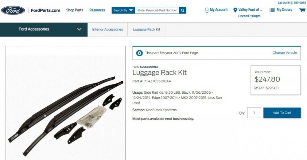
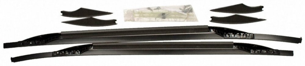
Document download link> Edge-MKX (2007-2014) Roof Side Rails Kit - Installation Instructions.pdf Don't throw away the roof channel trim strips and plastic trim strip retainer pieces that are removed in order to accomplish the roof rail installation. Occasionally, Forum members come looking for those parts, to restore their Edge/MKX into a non-roof-racked vehicle -- and then, you'll be able to help them out. Good luck!
-
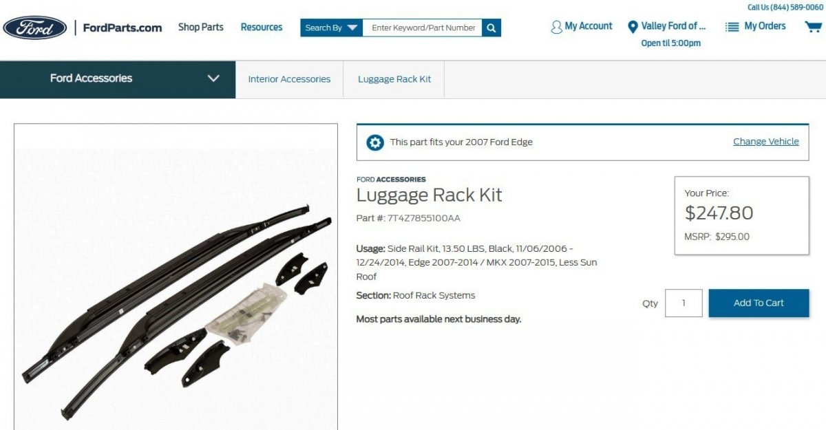
DO NOT PAY $400 for a set of used OEM Roof Rails. From Ford's online parts website (web page link)... While not recommended by Ford, Forum member scguru92 shared his method of installing roof rails with aftermarket cross bars on a Vista Roof Edge in this discussion, which provides insights for roof rail installation on non-Vista Roof Edges, as well. Web searching the Roof Rails part number (weblink) may provide better pricing than Ford's online parts website from other online OEM parts sellers. Good luck!
-
2014 daytime running light issue
Haz replied to Jhead85's topic in Glass, Lenses, Lighting, Mirrors, Sunroof (BAMR), Wipers
From 2014 Edge Workshop Manual, with emphasis added... Headlamps The headlamp system is a dual-beam pattern system. It consists of a single replaceable headlamp bulb in each headlamp assembly. The vehicle may come equipped with halogen or High Intensity Discharge (HID) bulbs. The headlamp assembly has the park/turn and side marker lamp integrated into the headlamp assembly. Vehicles with HID headlamps utilize ballasts to provide the necessary voltage to illuminate the HID bulbs. When the high beams are requested, a shutter within each headlamp is activated. This changes the headlamp beam pattern to illuminate a greater distance. Parking Lamps The parking lamps illuminate when requested from the headlamp switch or the autolamp system. The front parking and side marker lamps are integrated into the headlamp assemblies and the front auxiliary parking lamps are located in the front bumper cover. The rear parking and side marker lamps are located in the rear lamp assemblies and the liftgate lamps are locate on the outboard sides of the liftgate. Daytime Running Lamps (DRL) NOTE: The Daytime Running Lamps (DRL) are a programmable parameter for this vehicle. For vehicles with halogen headlamps: Daytime Running Lamps (DRL) can be enabled/disabled using the BCM Programmable Parameter, DRL Type. the factory selected DRL system operates the low beam headlamps at a reduced intensity. when enabling the DRL using a scan tool, two modes of operation can be selected. The low beam headlamps will illuminate at a reduced intensity (halogen headlamps) or the front turn lamps will illuminate continuously (not flashing) at full intensity. For vehicles with High Intensity Discharge (HID) headlamps: NOTICE: Do not enable Low Beams DRL mode If the vehicle is equipped with High Intensity Discharge (HID) headlamps. If Low Beams DRL mode is enabled, damage to the headlamp ballast may occur. Daytime Running Lamps (DRL) can be enabled/disabled using the BCM Programmable Parameter, DRL Type. the factory selected DRL system operates the front turn lamps illuminate continuously (not flashing) at full intensity. when enabling the DRL using a scan tool, only one mode of operation should be selected. The front turn lamps will illuminate continuously (not flashing) at full intensity. The DRL are activated when the following conditions are met: the ignition is in RUN the headlamps have not been turned on by the autolamp system or the headlamp switch the transmission is not in park Download links to relevant sections of the 2014 Edge Workshop Manual > Exterior Lighting - Description and Operation - 2014 Edge Workshop Manual.pdf Module Configuration - Diagnosis and Testing - 2014 Edge Workshop Manual.pdf Headlamps - Diagnosis and Testing - 2014 Edge Workshop Manual.pdf Daytime Running Lamps (DRL) - Diagnosis and Testing - 2014 Edge Workshop Manual.pdf Body Control Module (BCM) - Diagnosis and Testing - 2014 Edge Workshop Manual.pdf HID Headlamps Wiring Diagram - 2014 Edge Workshop Manual.pdf Halogen Headlamps Wiring Diagram - 2014 Edge Workshop Manual.pdf Auxiliary Parking Lamps Wiring Diagram - 2014 Edge Workshop Manual.pdf Front Lighting to BCM Wiring Diagram - 2014 Edge Workshop Manual.pdf BCM to Exterior Lighting Wiring Diagram - 2014 Edge Workshop Manual.pdf Left Headlamp - Connector C1021A Details - 2014 Edge Workshop Manual.pdf Right Headlamp - Connector C1041A Details - 2014 Edge Workshop Manual.pdf Left Front Auxiliary Parking Lamp - Connector C1445 Details - 2014 Edge Workshop Manual.pdf Right Front Auxiliary Parking Lamp - Connector C1446 Details - 2014 Edge Workshop Manual.pdf Left Front Auxiliary Parking Lamp - G105 Ground Location - 2014 Edge Workshop Manual.pdf Right Front Auxiliary Parking Lamp - G107 Ground Location - 2014 Edge Workshop Manual.pdf Per the above Workshop Manual descriptions and the above-linked wiring diagrams, the LED strip lights you circled in your photo are auxiliary parking lamps that light when the parking or headlamps are lit, whereas the programmable DRL parameters provide either for a reduced voltage low beam or nearly full-time lit front turn signal lamps in the headlamp assembly. If your pre-collision experience was the auxiliary parking lamps lighting whenever the engine is running, then your final-year GEN 1 Edge is behaving like a GEN 2 Edge should, according to this recent discussion, though the Workshop Manual documents indicate your Edge should be lighting the LED strips only when the parking or headlamps are turned on. One thing you may want to check -- the G105 ground connection on the left front in the vicinity of the collision repair, just to make sure it was reattached, and perhaps the G107 ground on the right front if you had to perform any disassembly on that side to facilitate your repair. Good luck! -
Nothing to offer on the steering wheel, but I do want to acknowledge your fine artistry, especially given this subject matter... Good luck!
-
Ford's FordParts.com site has a VIN-based search function that might be helpful toward identifying the correct USB Media Hub. Or telephone them at (844)589-0060. Good luck!

-
This is may be the most comprehensive listing of USB Media Hub part numbers, their application across various Ford & Lincoln vehicles, along with photos showing dimensions. Good luck!
-FordParts.jpg.596b5983869211efa47351f0a2a4243f.jpg)

PowerSourceWiringDiagramHighlighted-2016EdgeWorkshopManual.jpg.b85211dcb9f9d9f3e932280adf189b8c.jpg)
-TopViewDiagram-2016EdgeWorkshopManual.jpg.8f3d841e22e84d3b5fdc0bedfa3de13d.jpg)
Image1-FordPartsWebsite.jpg.45e97dbf2b401ce801e82a3ef4a9a602.jpg)
Image2-FordPartsWebsite.jpg.3c3239aa7be51690a6fc5efddae01a35.jpg)
Image3-FordPartsWebsite.jpg.eb7135bf91854216bfb4f343e3a06df3.jpg)
Image4-FordPartsWebsite.jpg.b7d5e0126754f32936fcc2eb641f0091.jpg)
-BottomViewDiagramHighlighted-2016EdgeWorkshopManual.jpg.fbc484435c876300676161f15faaa762.jpg)
DiagramHighlighted-2016EdgeWorkshopManual.jpg.559c095ad96d7ff1e4aae9997a305264.jpg)
ImageHighlighted-FordPartsWebsite.jpg.f6744f72ed6bc11f8b2f110b6093b6dc.jpg)