Haz
-
Posts
1,568 -
Joined
-
Last visited
-
Days Won
439
Content Type
Profiles
Forums
Gallery
Everything posted by Haz
-
It was my decision to provide the two sentences -- and short answers are not usually my 'want'. I included it only to confirm Kclonn's & omar302's observations on the ST's transmission. If fault exists, it is mine, not Ford's. Good luck!
-
To supplement this Special Service Message, below are Module Configuration and Parameter Charts for Model Year 2007 through 2022 Edge-MKX/Nautilus... 2007 Edge-MKX Module Name Reprogram/ Flash Capable Requires PMI Requires Adaptive Learning Requires Calibration Available Programmable Parameters 4X4 control module Yes No No No None ACM Yes Yes No No None ABS module Yes Yes No IVD initialization None DCSM Yes Yes No No None DSM Yes Yes No No Easy entry/exit DSP module Yes Yes No No None IC Yes Yes No No Belt-Minder® enable/disable Overspeed warning Transit mode enable/disable Headlamp control module (HCM) Yes No No No None Heating ventilation air conditioning (HVAC) module Yes No No No None Occupant classification system module (OCSM) Yes No No OCS re-zero None PAM No Yes No No None Liftgate/trunk module (LTM) Yes No No No None PCM Yes Yes Yes No Axle ratio Tire size Speed control enable/disable RCM Yes Yes No No Belt-Minder® enable/disable RETM Yes Yes No No Language English/ Spanish/French SDARS module enable/disable SDARS module Yes Yes No No None SJB Yes Yes No Tire pressure monitoring system (TPMS) sensor training Autolock and auto un-lock mode Daytime running lamp (DRL) enable/disable Perimeter lighting mode Stoplamp outage enable/disable Steering angle sensor module (SASM) Yes No No No None 2008 Edge-MKX Module Name Reprogram/ Flash Capable Requires PMI Requires Adaptive Learning Requires Calibration Available Programmable Parameters ABS module Yes Yes No IVD initialization None APIM Yes Yes No No None ACM Yes Yes No No Phone module DSP module Yes Yes No No None DSM Yes Yes No No Easy entry/exit DCSM Yes Yes No No None Headlamp control module (HCM) Yes No No No None HVAC module Yes No No No None IC Yes Yes No No Belt-Minder® Overspeed warning Transit mode Liftgate/trunk module (LTM) Yes No No No None Occupant classification system module (OCSM) Yes No No OCS re-zero None PAM No Yes No No None PCM Yes Yes Yes No Axle ratio Tire size Speed control present RETM Yes Yes No No Language English/ Spanish/French SDARS RCM Yes Yes No No Driver seat Belt-Minder® Passenger seat Belt-Minder® SDARS module Yes Yes No No None SJB Yes Yes No Tire pressure monitoring system (TPMS) sensor training Autolocks Auto un-locking Daytime running lamps (DRL) Perimeter lighting mode Stoplamp outage enable/disable Steering angle sensor module (SASM) Yes No No No None 4X4 control module Yes No No No None 2009 Edge-MKX Module Module Address Requires PMI Reprogram/ Flash Capable Requires Adaptive Learning or Calibration Available Programmable Parameters 4X4 control module 761 No Yes No None ABS module 760 Yes Yes IVD initialization None ACM 727 Yes Yes No Phone module (except navigation) Reverse park aid APIM (navigation only) Destination (navigation only) SDARS module (navigation only) Tuner region (navigation only) APIM 7D0 Yes Yes No None Audio DSP module 783 Yes Yes No None DCSM 776 Yes Yes No None DSM 744 Yes Yes No Easy entry/exit Headlamp Control Module (HCM) 734 No Yes No None HVAC module 733 No Yes No None IC 720 Yes Yes No Belt-Minder® Overspeed warning Transit mode Liftgate/Trunk Module (LTM) 775 No Yes No None Occupant Classification System Module (OCSM) 765 No Yes OCS re-zero None PAM 736 Yes No No None PCM 7E0 Yes Yes Adaptive airflow Idle speed Refueling event Fuel trim Axle ratio Tire size Speed control present RCM 737 Yes Yes No Driver seat Belt-Minder® Passenger seat Belt-Minder® SDARS module 782 Yes Yes No None SJB 726 Yes Yes Tire Pressure Monitoring System (TPMS) sensor training Autolocks Daytime Running Lamps (DRL) Global open Perimeter lighting mode Stop lamp outage enable/disable Tire placard pressure Steering Angle Sensor Module (SASM) 797 No Yes No None 2010 Edge-MKX Module Module Address Requires PMI Reprogram/ Flash Capable Requires Adaptive Learning or Calibration Available Programmable Parameters 4X4 control module 761 No Yes No None ABS module 760 Yes Yes IVD initialization None Accessory Protocol Interface Module (APIM) 7D0 Yes Yes No Stereo in pass-through Audio Front Control Module (ACM) 727 Yes Yes No Phone module (except navigation) Reverse park aid APIM (navigation only) Destination (navigation only) SDARS module (navigation only) Tuner region (navigation only) Audio Digital Signal Processing (DSP) module 783 Yes Yes No None Driver Seat Module (DSM) 744 Yes Yes No Easy entry/exit Dual Climate Controlled Seat Module (DCSM) 776 Yes Yes No None Global Positioning System Module (GPSM) 701 No No No None Headlamp Control Module (HCM) 734 No Yes No None HVAC module 733 No Yes No None Instrument Cluster (IC) 720 Yes Yes No Belt-Minder® Overspeed warning Transit mode Liftgate/Trunk Module (LTM) 775 No Yes No None Occupant Classification System Module (OCSM) 765 No Yes OCS re-zero None Parking Aid Module (PAM) 736 Yes No No None PCM 7E0 Yes Yes Adaptive airflow Idle speed Refueling event Fuel trim Axle ratio Tire size Speed control present Restraints Control Module (RCM) 737 Yes Yes No Driver seat Belt-Minder® Passenger seat Belt-Minder® Satellite Digital Audio Receiver System (SDARS) module 782 Yes Yes No None Smart Junction Box (SJB) 726 Yes Yes Tire Pressure Monitoring System (TPMS) sensor training Autolock Auto-unlock Daytime Running Lamps (DRL) Global open Perimeter lighting mode Stop lamp outage enable/disable Tire placard pressure Steering Angle Sensor Module (SASM) 797 No Yes No None 2011 Edge-MKX Module Name Requires PMI Reprogram/ Flash Capable Requires Adaptive Learning or Calibration Available Programmable Parameters Accessory Protocol Interface Module (APIM) Yes Yes No Clock display ABS module Yes Yes IVD initialization Tire size (must match BCM ) Audio Front Control Module (ACM) Yes Yes No None Audio Digital Signal Processing (DSP) module Yes Yes No None Body Control Module (BCM) Yes Yes No Axle ratio Courtesy lamp dimming type Police dark car feature Smart unlocking Stop and turn lamp outage configuration Tire placard pressure Tire size (must match ABS module) Daytime running lamps Cruise-Control Module (C-CM) Yes Yes No None Driver Seat Module (DSM) Yes Yes No None Dual Climate Controlled Seat Module (DCSM) Yes Yes No None Front Lighting Control Module (FLM) No Yes No None Front Controls Interface Module (FCIM) No Yes No None Front Control/Display Interface Module (FCDIM) Yes Yes No None Global Positioning System Module (GPSM) No Yes No None Heated Steering Wheel Module (HSWM) Yes Yes No None Headlamp Control Module (HCM) No Yes No None Head Up Display (HUD) module No Yes No None HVAC module Yes Yes No None Instrument Panel Cluster (IPC) Yes Yes No Belt-Minder® English/Metric Language Rear fog lamps Rear reverse gear wipe Liftgate/Trunk Module (LTM) No Yes No None Occupant Classification System Module (OCSM) No Yes OCS re-zero None Parking Aid Module (PAM) No Yes No None PCM Yes Yes Adaptive airflow Axle ratio Idle speed Refueling event Fuel trim present Tire size None Remote Function Actuator (RFA) module Yes Yes No Intelligent Access (IA) Restraints Control Module (RCM) Yes Yes No Driver Belt-Minder® Passenger Belt-Minder® Steering Column Control Module (SCCM) Yes Yes No None Side Obstacle Detection Control Module - Left (SOD-L) Yes Yes No On/Off Side Obstacle Detection Control Module - Right (SOD-R) Yes Yes No On/Off Tire Pressure Monitor (TPM) No Yes No None 2012 Edge-MKX Module Name Requires PMI Reprogram/ Flash Capable Requires Adaptive Learning or Calibration Available Programmable Parameters Accessory Protocol Interface Module (APIM) Yes Yes No Clock display Navigation application ABS module Yes Yes IVD initialization Tire size (must match BCM ) Audio Front Control Module (ACM) Yes Yes No MP3 CD text conversion Audio Digital Signal Processing (DSP) module Yes Yes No None Body Control Module (BCM) Yes Yes No Axle ratio Courtesy lamp dimming type Daytime Running Lamps (DRL) feature Daytime Running Lamps (DRL) type Police dark car feature Smart unlocking Stop and turn lamp outage configuration Tire placard pressure Tire size (must match ABS module) Cruise-Control Module (C-CM) Yes Yes No None Driver Seat Module (DSM) Yes Yes No None Dual Climate Controlled Seat Module (DCSM) Yes Yes No None Front Lighting Control Module (FLM) No Yes No None Front Controls Interface Module (FCIM) No Yes No None Front Control/Display Interface Module (FCDIM) Yes Yes No Date format Global Positioning System Module (GPSM) Yes Yes No None Heated Steering Wheel Module (HSWM) Yes Yes No None Headlamp Control Module (HCM) No Yes No None Head Up Display (HUD) module No Yes No None HVAC module Yes Yes No None Instrument Panel Cluster (IPC) Yes Yes No Back up chime Belt-Minder® Courtesy wipe after wash English/Metric Gallon display type Navigation Rear fog lamps Rear reverse gear wipe Liftgate/Trunk Module (LTM) No Yes No None Occupant Classification System Module (OCSM) No Yes OCS re-zero None Parking Aid Module (PAM) No Yes No None PCM Yes Yes Adaptive airflow Axle ratio Idle speed Refueling event Fuel trim present Tire size None Remote Function Actuator (RFA) module Yes Yes No Autolock Autounlock One/two stage unlock Intelligent Access (IA) Restraints Control Module (RCM) Yes Yes No Driver Belt-Minder® Passenger Belt-Minder® Steering Column Control Module (SCCM) Yes Yes No None Side Obstacle Detection Control Module - Left (SOD-L) Yes Yes No Blind Spot Information System (BLIS®) Cross Traffic Alert (CTA) Side Obstacle Detection Control Module - Right (SOD-R) Yes Yes No BLIS® CTA Tire Pressure Monitor (TPM) (also known as the Radio Transceiver Module [RTM]) No Yes No None Transmission Control Module (TCM) Yes Yes No None 2013 Edge-MKX Module Name Requires PMI Reprogram/ Flash Capable Requires Adaptive Learning or Calibration Available Programmable Parameters Accessory Protocol Interface Module (APIM) Yes Yes No Clock display Navigation application ABS module Yes Yes IVD initialization Tire size (must match BCM ) Audio Front Control Module (ACM) Yes Yes No MP3 CD text conversion Audio Digital Signal Processing (DSP) module Yes Yes No None Body Control Module (BCM) Yes Yes No Axle ratio Courtesy lamp dimming type Daytime Running Lamps (DRL) feature Daytime Running Lamps (DRL) type Police dark car feature Smart unlocking Stop and turn lamp outage configuration Tire placard pressure Tire size (must match ABS module) Cruise-Control Module (C-CM) Yes Yes No None Driver Seat Module (DSM) Yes Yes No None Dual Climate Controlled Seat Module (DCSM) Yes Yes No None Front Lighting Control Module (FLM) No Yes No None Front Controls Interface Module (FCIM) No Yes No None Front Control/Display Interface Module (FCDIM) Yes Yes No Date format Global Positioning System Module (GPSM) Yes Yes No None Heated Steering Wheel Module (HSWM) Yes Yes No None Headlamp Control Module (HCM) No Yes No None Head Up Display (HUD) module No Yes No None HVAC module Yes Yes No None Instrument Panel Cluster (IPC) Yes Yes No Back up chime Belt-Minder® Courtesy wipe after wash English/Metric Gallon display type Navigation Rear fog lamps Rear reverse gear wipe Liftgate/Trunk Module (LTM) No Yes No None Occupant Classification System Module (OCSM) No Yes OCS re-zero None Parking Aid Module (PAM) No Yes No None PCM Yes Yes Adaptive airflow Axle ratio Idle speed Refueling event Fuel trim present Tire size None Remote Function Actuator (RFA) module Yes Yes No Autolock Autounlock One/two stage unlock Intelligent Access (IA) Restraints Control Module (RCM) Yes Yes No Driver Belt-Minder® Passenger Belt-Minder® Steering Column Control Module (SCCM) Yes Yes No None Side Obstacle Detection Control Module - Left (SOD-L) Yes Yes No Blind Spot Information System (BLIS®) Cross Traffic Alert (CTA) Side Obstacle Detection Control Module - Right (SOD-R) Yes Yes No BLIS® CTA Tire Pressure Monitor (TPM) (also known as the Radio Transceiver Module [RTM]) No Yes No None Transmission Control Module (TCM) Yes Yes No None 2014 Edge-MKX Module Name Requires PMI Reprogram/ Flash Capable Requires Adaptive Learning or Calibration Available Programmable Parameters Accessory Protocol Interface Module (APIM) Yes Yes No Clock display Navigation application ABS module Yes Yes IVD initialization Tire size (must match BCM ) Audio Front Control Module (ACM) Yes Yes No MP3 CD text conversion Audio Digital Signal Processing (DSP) module Yes Yes No None Body Control Module (BCM) Yes Yes No Axle ratio Courtesy lamp dimming type Daytime Running Lamps (DRL) feature Daytime Running Lamps (DRL) type Police dark car feature Smart unlocking Stop and turn lamp outage configuration Tire placard pressure Tire size (must match ABS module) Cruise-Control Module (C-CM) Yes Yes No None Driver Seat Module (DSM) Yes Yes No None Dual Climate Controlled Seat Module (DCSM) Yes Yes No None Front Lighting Control Module (FLM) No Yes No None Front Controls Interface Module (FCIM) No Yes No None Front Control/Display Interface Module (FCDIM) Yes Yes No Date format Global Positioning System Module (GPSM) Yes Yes No None Heated Steering Wheel Module (HSWM) Yes Yes No None Headlamp Control Module (HCM) No Yes No None Head Up Display (HUD) module No Yes No None HVAC module Yes Yes No None Instrument Panel Cluster (IPC) Yes Yes No Back up chime Belt-Minder® Courtesy wipe after wash English/Metric Gallon display type Navigation Rear fog lamps Rear reverse gear wipe Liftgate/Trunk Module (LTM) No Yes No None Occupant Classification System Module (OCSM) No Yes OCS re-zero None Parking Aid Module (PAM) No Yes No None PCM Yes Yes Adaptive airflow Axle ratio Idle speed Refueling event Fuel trim present Tire size None Remote Function Actuator (RFA) module Yes Yes No Autolock Autounlock One/two stage unlock Intelligent Access (IA) Restraints Control Module (RCM) Yes Yes No Driver Belt-Minder® Passenger Belt-Minder® Steering Column Control Module (SCCM) Yes Yes No None Side Obstacle Detection Control Module - Left (SOD-L) Yes Yes No Blind Spot Information System (BLIS®) Cross Traffic Alert (CTA) Side Obstacle Detection Control Module - Right (SOD-R) Yes Yes No BLIS® CTA Tire Pressure Monitor (TPM) (also known as the Radio Transceiver Module [RTM]) No Yes No None Transmission Control Module (TCM) Yes Yes No None 2015 Edge Module Name Module Address Programmable Module Installation (PMI) Available Reprogram/Flash Capable Requires Adaptive Learning or Calibration Available Progammable Parameters APIM 7D0 Yes Yes No None ABS module 760 Yes Yes IVD initialization EPB apply and release Trailer sway assist ACM 727 Yes Yes No None BCM 726 Yes Yes Ambient lighting calibration Rear view camera calibration Remote start enable/disable Perimeter alarm Tire pressure CCM 764 Yes Yes Radar horizontal and vertical alignment calibration None DSP 783 Yes Yes No None DACMC (integrated with ACM ) 7D5 Yes Yes No None DC / DC converter control module (Voltage Quality Module [VQM]) 746 Yes Yes No None DDM 740 Yes Yes Windows initialization None DSM 744 Yes Yes No None SCME 776 Yes Yes No None FCDIM 7A5 Yes Yes No None FCIM 7A7 Yes Yes No None GWM 716 Yes Yes No None GPSM 701 Yes Yes No None HUD module 7B2 No No No None HSWM 714 Yes Yes No None IPC 720 Yes Yes No Daytime running lamps control function Remote start feature Remote start - climate settings Driver seat Passenger seat Rear defrost Steering wheel IPMA 706 Yes Yes Camera calibration None IPMB 7B1 Yes Yes Camera calibration None OCSM 765 No No OCSM re-zero None PAM (integrated with BCM ) 736 Yes Yes No None PSCM 730 Yes Yes No None PCM 7E0 Yes Yes Misfire Monitor Neutral Profile Correction procedure None PDM 741 Yes Yes Windows initialization None RTM 751 Yes Yes No None RGTM 775 Yes Yes No None RCM 737 Yes Yes No None SODL 7C4 Yes Yes No BLIS/CTA enable/disable Blockage enable/disable SODR 7C6 Yes Yes No BLIS/CTA enable/disable Blockage enable/disable SASM 797 Yes Yes Adaptive steering wheel angle sensor trim adjustment None SECM 7C5 Yes Yes Adaptive steering wheel angle sensor trim adjustment Actuator trim procedure None SCCM 724 Yes Yes No None TRM 791 Yes Yes No None 2015 MKX Module Name Requires PMI Reprogram/ Flash Capable Requires Adaptive Learning or Calibration Available Programmable Parameters Accessory Protocol Interface Module (APIM) Yes Yes No Clock display Navigation application ABS module Yes Yes IVD initialization Tire size (must match BCM ) Audio Front Control Module (ACM) Yes Yes No MP3 CD text conversion Audio Digital Signal Processing (DSP) module Yes Yes No None Body Control Module (BCM) Yes Yes No Axle ratio Courtesy lamp dimming type Daytime Running Lamps (DRL) feature Daytime Running Lamps (DRL) type Police dark car feature Smart unlocking Stop and turn lamp outage configuration Tire placard pressure Tire size (must match ABS module) Cruise-Control Module (C-CM) Yes Yes No None Driver Seat Module (DSM) Yes Yes No None Dual Climate Controlled Seat Module (DCSM) Yes Yes No None Front Lighting Control Module (FLM) No Yes No None Front Controls Interface Module (FCIM) No Yes No None Front Control/Display Interface Module (FCDIM) Yes Yes No Date format Global Positioning System Module (GPSM) Yes Yes No None Heated Steering Wheel Module (HSWM) Yes Yes No None Headlamp Control Module (HCM) No Yes No None Head Up Display (HUD) module No Yes No None HVAC module Yes Yes No None Instrument Panel Cluster (IPC) Yes Yes No Back up chime Belt-Minder® Courtesy wipe after wash English/Metric Gallon display type Navigation Rear fog lamps Rear reverse gear wipe Liftgate/Trunk Module (LTM) No Yes No None Occupant Classification System Module (OCSM) No Yes OCS re-zero None Parking Aid Module (PAM) No Yes No None PCM Yes Yes Adaptive airflow Axle ratio Idle speed Refueling event Fuel trim present Tire size None Remote Function Actuator (RFA) module Yes Yes No Autolock Autounlock One/two stage unlock Intelligent Access (IA) Restraints Control Module (RCM) Yes Yes No Driver Belt-Minder® Passenger Belt-Minder® Steering Column Control Module (SCCM) Yes Yes No None Side Obstacle Detection Control Module - Left (SOD-L) Yes Yes No Blind Spot Information System (BLIS®) Cross Traffic Alert (CTA) Side Obstacle Detection Control Module - Right (SOD-R) Yes Yes No BLIS® CTA Tire Pressure Monitor (TPM) (also known as the Radio Transceiver Module [RTM]) No Yes No None Transmission Control Module (TCM) Yes Yes No None 2016 Edge Module Name Module Address Programmable Module Installation (PMI) Available Reprogram/Flash Capable Requires Adaptive Learning or Calibration Available Progammable Parameters APIM 7D0 Yes Yes No None ABS module 760 Yes Yes IVD initialization EPB apply and release Trailer sway assist ACM 727 Yes Yes No None BCM 726 Yes Yes Ambient lighting calibration Rear view camera calibration Remote start enable/disable Perimeter alarm Tire pressure CCM 764 Yes Yes Radar horizontal and vertical alignment calibration None DSP 783 Yes Yes No None DACMC (integrated with ACM ) 7D5 Yes Yes No None DC / DC converter control module (Voltage Quality Module [VQM]) 746 Yes Yes No None DDM 740 Yes Yes Windows initialization None DSM 744 Yes Yes No None SCME 776 Yes Yes No None FCDIM 7A5 Yes Yes No None FCIM 7A7 Yes Yes No None GWM 716 Yes Yes No None GPSM (without touchscreen) 701 Yes Yes No None HUD module 7B2 No No No None HSWM 714 Yes Yes No None IPC 720 Yes Yes No Daytime running lamps control function Remote start feature Remote start - climate settings Driver seat Passenger seat Rear defrost Steering wheel IPMA 706 Yes Yes Camera calibration None IPMB 7B1 Yes Yes Camera calibration None OCSM 765 No No OCSM re-zero None PAM (integrated with BCM ) 736 Yes Yes No None PSCM 730 Yes Yes No None PCM 7E0 Yes Yes Misfire Monitor Neutral Profile Correction procedure None PDM 741 Yes Yes Windows initialization None RTM 751 Yes Yes No None RGTM 775 Yes Yes No None RCM 737 Yes Yes No None SODL 7C4 Yes Yes No BLIS/CTA enable/disable Blockage enable/disable SODR 7C6 Yes Yes No BLIS/CTA enable/disable Blockage enable/disable SASM 797 Yes Yes Adaptive steering wheel angle sensor trim adjustment None SECM 7C5 Yes Yes Adaptive steering wheel angle sensor trim adjustment Actuator trim procedure None SCCM 724 Yes Yes No None TRM 791 Yes Yes No None 2016 MKX Module Name Module Address Programmable Module Installation (PMI) Available Reprogram/Flash Capable Requires Adaptive Learning or Calibration Available Progammable Parameters APIM 7D0 Yes Yes No None ABS module 760 Yes Yes IVD initialization EPB apply and release Trailer sway assist ACM 727 Yes Yes No None BCM 726 Yes Yes Ambient lighting calibration Rear view camera calibration Remote start enable/disable Perimeter alarm Tire pressure CCM 764 Yes Yes Radar horizontal and vertical alignment calibration None DSP 783 Yes Yes No None DACMC (integrated with ACM ) 7D5 Yes Yes No None DC / DC converter control module (Voltage Quality Module [VQM]) 746 Yes Yes No None DDM 740 Yes Yes Windows initialization None DSM 744 Yes Yes No None SCME 776 Yes Yes No None FCIM 7A7 Yes Yes No None GWM 716 Yes Yes No None GPSM (if equipped with SYNC 2) 701 Yes Yes No None HCM 734 Yes No LED Lamp Driver Module Initialization None HUD module 7B2 No No No None HSWM 714 Yes Yes No None IPC 720 Yes Yes No Daytime running lamps control function Remote start feature Remote start - climate settings Driver seat Passenger seat Rear defrost Steering wheel IPMA 706 Yes Yes Camera calibration None IPMB 7B1 Yes Yes Camera calibration None OCSM 765 No No OCSM re-zero None PAM (integrated with BCM ) 736 Yes Yes No None Passenger front seat module (SCMB) 7A3 Yes No No None PSCM 730 Yes Yes No None PCM 7E0 Yes Yes Misfire Monitor Neutral Profile Correction procedure None PDM 741 Yes Yes Windows initialization None RTM 751 Yes Yes No None RACM 774 No No No None RGTM 775 Yes Yes No None RCM 737 Yes Yes No None SODL 7C4 Yes Yes No BLIS/CTA enable/disable Blockage enable/disable SODR 7C6 Yes Yes No BLIS/CTA enable/disable Blockage enable/disable SCMG 712 Yes No No None SCMH 713 Yes No No None SASM 797 Yes Yes Adaptive steering wheel angle sensor trim adjustment None SECM 7C5 Yes Yes Adaptive steering wheel angle sensor trim adjustment Actuator trim procedure Vehicle tune selector Wheel/tire diameter SCCM 724 Yes Yes No None TCU 754 Yes No No None TRM 791 Yes Yes No None VDM 721 Yes Yes Ride height calibration None 2017 Edge Module Name Module Address Programmable Module Installation (PMI) Available Reprogram/Flash Capable Requires Adaptive Learning or Calibration Available Progammable Parameters APIM 7D0 Yes Yes No None ABS module 760 Yes Yes IVD initialization EPB apply and release Trailer sway assist ACM 727 Yes Yes No None BECMB 723 Yes No No None BCM 726 Yes Yes Ambient lighting calibration Rear view camera calibration Remote start enable/disable Perimeter alarm Tire pressure CCM 764 Yes Yes Radar horizontal and vertical alignment calibration None DSP 783 Yes Yes No None DACMC (integrated with ACM ) 7D5 Yes Yes No None DC / DC converter control module (Voltage Quality Module [VQM]) 746 Yes Yes No None DDM 740 Yes Yes Windows initialization None DSM 744 Yes Yes No None SCME 776 Yes Yes No None FCDIM 7A5 Yes Yes No None FCIM 7A7 Yes Yes No None GWM 716 Yes Yes No None GPSM (without touchscreen) 701 Yes Yes No None HUD module 7B2 No No No None HSWM 714 Yes Yes No None IPC 720 Yes Yes No Daytime running lamps control function Remote start feature Remote start - climate settings Driver seat Passenger seat Rear defrost Steering wheel IPMA 706 Yes Yes Camera calibration None IPMB 7B1 Yes Yes Camera calibration None OCSM 765 No No OCSM re-zero None PAM (integrated with BCM ) 736 Yes Yes No None PSCM 730 Yes Yes No None PCM 7E0 Yes Yes Misfire Monitor Neutral Profile Correction procedure None PDM 741 Yes Yes Windows initialization None RTM 751 Yes Yes No None RGTM 775 Yes Yes No None RCM 737 Yes Yes No None SODL 7C4 Yes Yes No BLIS/CTA enable/disable Blockage enable/disable SODR 7C6 Yes Yes No BLIS/CTA enable/disable Blockage enable/disable SASM 797 Yes Yes Adaptive steering wheel angle sensor trim adjustment None SECM 7C5 Yes Yes Adaptive steering wheel angle sensor trim adjustment Actuator trim procedure None SCCM 724 Yes Yes No None TRM 791 Yes Yes No None 2017 MKX Module Name Module Address Programmable Module Installation (PMI) Available Reprogram/Flash Capable Requires Adaptive Learning or Calibration Available Progammable Parameters APIM 7D0 Yes Yes No None ABS module 760 Yes Yes IVD initialization EPB apply and release Trailer sway assist ACM 727 Yes Yes No None BECMB 723 Yes No No None BCM 726 Yes Yes Ambient lighting calibration Rear view camera calibration Remote start enable/disable Perimeter alarm Tire pressure CCM 764 Yes Yes Radar horizontal and vertical alignment calibration None DSP 783 Yes Yes No None DACMC (integrated with ACM ) 7D5 Yes Yes No None DC / DC converter control module (Voltage Quality Module [VQM]) 746 Yes Yes No None DDM 740 Yes Yes Windows initialization None DSM 744 Yes Yes No None SCME 776 Yes Yes No None FCIM 7A7 Yes Yes No None GWM 716 Yes Yes No None HCM 734 Yes No LED Lamp Driver Module Initialization None HUD module 7B2 No No No None HSWM 714 Yes Yes No None IPC 720 Yes Yes No Daytime running lamps control function Remote start feature Remote start - climate settings Driver seat Passenger seat Rear defrost Steering wheel IPMA 706 Yes Yes Camera calibration None IPMB 7B1 Yes Yes Camera calibration None OCSM 765 No No OCSM re-zero None PAM (integrated with BCM ) 736 Yes Yes No None Passenger front seat module (SCMB) 7A3 Yes No No None PSCM 730 Yes Yes No None PCM 7E0 Yes Yes Misfire Monitor Neutral Profile Correction procedure None PDM 741 Yes Yes Windows initialization None RTM 751 Yes Yes No None RACM 774 No No No None RGTM 775 Yes Yes No None RCM 737 Yes Yes No None SODL 7C4 Yes Yes No BLIS/CTA enable/disable Blockage enable/disable SODR 7C6 Yes Yes No BLIS/CTA enable/disable Blockage enable/disable SCMG 712 Yes No No None SCMH 713 Yes No No None SASM 797 Yes Yes Adaptive steering wheel angle sensor trim adjustment None SECM 7C5 Yes Yes Adaptive steering wheel angle sensor trim adjustment Actuator trim procedure Vehicle tune selector SCCM 724 Yes Yes No None TCU 754 Yes No No None TRM 791 Yes Yes No None VDM 721 Yes Yes Ride height calibration None 2018 Edge Module Name Module Address Programmable Module Installation (PMI) Available Reprogram/Flash Capable Requires Adaptive Learning or Calibration Available Progammable Parameters APIM 7D0 Yes Yes No None ABS module 760 Yes Yes IVD initialization EPB apply and release Trailer sway assist ACM 727 Yes Yes No None BECMB 723 Yes No No None BCM 726 Yes Yes Ambient lighting calibration Rear view camera calibration Remote start enable/disable Perimeter alarm Tire pressure CCM 764 Yes Yes Radar horizontal and vertical alignment calibration None DSP 783 Yes Yes No None DACMC (integrated with ACM ) 7D5 Yes Yes No None DC / DC converter control module (Voltage Quality Module [VQM]) 746 Yes Yes No None DDM 740 Yes Yes Windows initialization None DSM 744 Yes Yes No None SCME 776 Yes Yes No None FCDIM 7A5 Yes Yes No None FCIM 7A7 Yes Yes No None GWM 716 Yes Yes No None GPSM (without touchscreen) 701 Yes Yes No None HUD module 7B2 No No No None HSWM 714 Yes Yes No None IPC 720 Yes Yes No Daytime running lamps control function Remote start feature Remote start - climate settings Driver seat Passenger seat Rear defrost Steering wheel IPMA 706 Yes Yes Camera calibration None IPMB 7B1 Yes Yes Camera calibration None OCSM 765 No No OCSM re-zero None PAM (integrated with BCM ) 736 Yes Yes No None PSCM 730 Yes Yes No None PCM 7E0 Yes Yes Misfire Monitor Neutral Profile Correction procedure None PDM 741 Yes Yes Windows initialization None RTM 751 Yes Yes No None RGTM 775 Yes Yes No None RCM 737 Yes Yes No None SODL 7C4 Yes Yes No BLIS/CTA enable/disable Blockage enable/disable SODR 7C6 Yes Yes No BLIS/CTA enable/disable Blockage enable/disable SASM 797 Yes Yes Adaptive steering wheel angle sensor trim adjustment None SECM 7C5 Yes Yes Adaptive steering wheel angle sensor trim adjustment Actuator trim procedure None SCCM 724 Yes Yes No None TRM 791 Yes Yes No None 2018 MKX Module Name Module Address Programmable Module Installation (PMI) Available Reprogram/Flash Capable Requires Adaptive Learning or Calibration Available Programmable Parameters APIM 7D0 Yes Yes No None ABS module 760 Yes Yes IVD initialization EPB apply and release Trailer sway assist ACM 727 Yes Yes No None BECMB 723 Yes Yes No None BCM 726 Yes Yes Ambient lighting calibration Rear view camera calibration Autolock 1-5 DRL by autolamps initial validation DRL by autolamps 1-5 Front/rear tire placard (pressure) Perimeter alarm (except Japan) Remote start enable/disable CCM 764 Yes Yes Radar horizontal and vertical alignment calibration None DSP 783 Yes Yes No None DACMC (integrated with ACM ) 7D5 Yes Yes No ANC functionality ESE functionality DC / DC converter control module (Voltage Quality Module [VQM]) 746 Yes Yes No None DDM 740 Yes Yes Windows initialization None DSM 744 Yes Yes No None SCME 776 Yes Yes No None FCIM 7A7 Yes Yes No None GWM 716 Yes Yes No None HCM 734 Yes No LED Lamp Driver Module Initialization None HUD module 7B2 No No No None HSWM 714 Yes Yes No None IPC 720 Yes Yes No Autofold mirrors DRL control function Neutral tow Remote start feature Remote start - climate settings Driver seat Passenger seat Rear defrost Steering wheel IPMA 706 Yes Yes Camera calibration None IPMB 7B1 Yes Yes Camera calibration None OCSM 765 No No OCSM re-zero None PAM (integrated with BCM ) 736 Yes Yes No None SCMB 7A3 Yes No No None PSCM 730 Yes Yes No None PCM 7E0 Yes Yes Misfire Monitor Neutral Profile Correction procedure None PDM 741 Yes Yes Windows initialization None RTM 751 Yes Yes No None RACM 774 No No No None RGTM 775 Yes Yes No None RCM 737 Yes Yes No None SODL 7C4 Yes Yes No BLIS/CTA enable/disable Blockage enable/disable SODR 7C6 Yes Yes No BLIS/CTA enable/disable Blockage enable/disable SCMG 712 Yes No No None SCMH 713 Yes No No None SASM 797 Yes Yes Adaptive steering wheel angle sensor trim adjustment None SECM 7C5 Yes Yes Adaptive steering wheel angle sensor trim adjustment Actuator trim procedure Vehicle tune selector SCCM 724 Yes Yes No Rear wiper reverse wipe enable/disable TCU 754 Yes No No None TRM 791 Yes Yes No None VDM 721 Yes Yes Height sensor calibration None 2019 Edge Module Name Module Address Programmable Module Installation (PMI) Available Reprogram/Flash Capable Requires Adaptive Learning or Calibration Available Programmable Parameters ABS module 760 Yes Yes IVD initialization EPB apply and release None ACM 727 Yes Yes No None AHCM 7E3 Yes Yes No None APIM 7D0 Yes Yes No None AWD module 703 Yes Yes No None BCM 726 Yes Yes Ambient lighting calibration Rear view camera calibration Autolock enable DRL by autolamps Remote start enable/disable Perimeter alarm Tire pressure BECMB 723 Yes Yes No None CCM 764 Yes Yes Radar horizontal and vertical alignment calibration None DACMC (integrated with ACM ) 7D5 Yes Yes No ANC ESE DC / DC converter control module (Voltage Quality Module [VQM]) 746 Yes Yes No None DDM 740 Yes Yes Windows initialization None DSM 744 Yes Yes No None DSP 783 Yes Yes No None FCIM 7A7 Yes Yes No None GSM 732 Yes Yes No None GWM 716 Yes Yes No None HCM 734 Yes Yes No None HSWM 714 Yes Yes No None IPC 720 Yes Yes No None IPMA 706 Yes Yes Camera calibration None IPMB 7B1 Yes Yes Camera calibration None OCSM 765 No No OCSM re-zero None PAM (integrated with BCM ) 736 Yes Yes No None PSCM 730 Yes Yes No None PCM 7E0 Yes Yes Misfire Monitor Neutral Profile Correction procedure None PDM 741 Yes Yes Windows initialization None RCM 737 Yes Yes No None RGTM 775 Yes Yes No None RTM 751 Yes Yes No None SASM 797 Yes Yes Adaptive steering wheel angle sensor trim adjustment None SCCM 724 Yes Yes No None SCME 776 Yes Yes No None SECM 7C5 Yes Yes Adaptive steering wheel angle sensor trim adjustment Actuator trim procedure None SODL 7C4 Yes Yes No BLIS/CTA enable/disable Blockage enable/disable SODR 7C6 Yes Yes No BLIS/CTA enable/disable Blockage enable/disable TCU 754 Yes Yes No None TRM 791 Yes Yes No None WACM 725 Yes Yes No None 2019 Nautilus Module Name Module Address Programmable Module Installation (PMI) Available Reprogram/Flash Capable Requires Adaptive Learning or Calibration Available Progammable Parameters ABS module 760 Yes Yes IVD initialization EPB apply and release None ACM 727 Yes Yes No None APIM 7D0 Yes Yes No None AWD module 703 Yes No No None BECMB 723 Yes Yes No None BCM 726 Yes Yes Ambient lighting calibration Rear view camera calibration Autolock 1-4 DRL by autolamps initial validation DRL by autolamps 1-5 Front/rear tire placard (pressure) Perimeter alarm Remote start enable/disable CCM 764 Yes Yes Radar horizontal and vertical alignment calibration None DACMC (integrated with ACM ) 7D5 Yes Yes No ANC functionality ESE functionality DC / DC converter control module (Voltage Quality Module [VQM]) 746 Yes No No None DDM 740 Yes Yes Windows initialization None DSM 744 Yes No No None DSP 783 Yes No No None FCIM 7A7 Yes Yes No None GSM 732 No No No None GWM 716 Yes No No None HCM 734 Yes No LED Lamp Driver Module Initialization None HSWM 714 Yes No No None IPC 720 Yes No No None IPMA 706 Yes No Camera calibration None IPMB 7B1 Yes No Camera calibration None OCSM 765 No No OCSM re-zero None PAM (integrated with BCM ) 736 Yes Yes No None PCM 7E0 Yes Yes Misfire Monitor Neutral Profile Correction procedure None PDM 741 Yes Yes Windows initialization None PSCM 730 Yes Yes No None RACM 774 No No No None RCM 737 Yes No No None RGTM 775 Yes Yes No None RTM 751 Yes No No None SASM 797 Yes No Adaptive steering wheel angle sensor trim adjustment None SCCM 724 Yes No No None SCMB 7A3 Yes No No None SCME 776 Yes No No None SCMG 712 Yes No No None SCMH 713 Yes No No None SECM 7C5 Yes No Adaptive steering wheel angle sensor trim adjustment Actuator trim procedure None SODL 7C4 Yes No No BLIS/CTA enable/disable Blockage enable/disable SODR 7C6 Yes No No BLIS/CTA enable/disable Blockage enable/disable TCU 754 Yes No No None TRM 791 Yes No No None VDM 721 Yes Yes Height sensor calibration None WACM 725 Yes No No None 2020 Edge Module Name Module Address Programmable Module Installation (PMI) Available Reprogram/Flash Capable Requires Adaptive Learning or Calibration Available Programmable Parameters ABS module 760 Yes Yes IVD initialization EPB apply and release None ACM 727 Yes Yes No None AHCM 7E3 Yes No No None APIM 7D0 Yes No No None AWD module 703 Yes Yes No None BCM 726 Yes Yes Ambient lighting calibration Rear view camera calibration Autolock enable DRL by auto lamps Remote start enable/disable Perimeter alarm Tire pressure BECMB 723 Yes No No None CCM 764 Yes No Radar horizontal and vertical alignment calibration None DACMC (integrated with ACM ) 7D5 Yes Yes No ANC ESE DC / DC converter control module (Voltage Quality Module [VQM]) 746 Yes No No None DDM 740 Yes Yes Windows initialization None DSM 744 Yes No No None DSP 783 Yes No No None FCIM 7A7 Yes Yes No None GSM 732 No Yes No None GWM 716 Yes No No None HCM 734 Yes No No None HSWM 714 Yes No No None IPC 720 Yes No No None IPMA 706 Yes No Camera calibration None IPMB 7B1 Yes No Camera calibration None OCSM 765 No No OCSM re-zero None PAM (integrated with BCM ) 736 Yes Yes No None PSCM 730 Yes Yes No None PCM 7E0 Yes Yes Misfire Monitor Neutral Profile Correction procedure None PDM 741 Yes Yes Windows initialization None RCM 737 Yes No No None RGTM 775 Yes Yes No None RTM 751 Yes No No None SCCM 724 Yes No No None SCME 776 Yes No No None SODL 7C4 Yes No No BLIS/CTA enable/disable Blockage enable/disable SODR 7C6 Yes No No BLIS/CTA enable/disable Blockage enable/disable TCU 754 Yes No No None TRM 791 Yes No No None WACM 725 Yes No No None 2020 Nautilus Module Name Module Address Programmable Module Installation (PMI) Available Reprogram/Flash Capable Requires Adaptive Learning or Calibration Available Progammable Parameters ABS module 760 Yes Yes IVD initialization EPB apply and release None ACM 727 Yes Yes No None APIM 7D0 Yes Yes No None AWD module 703 Yes No No None BECMB 723 Yes Yes No None BCM 726 Yes Yes Ambient lighting calibration Rear view camera calibration Autolock 1-4 DRL by autolamps initial validation DRL by autolamps 1-5 Front/rear tire placard (pressure) Perimeter alarm Remote start enable/disable CCM 764 Yes Yes Radar horizontal and vertical alignment calibration None DACMC (integrated with ACM ) 7D5 Yes Yes No ANC functionality ESE functionality DC / DC converter control module (Voltage Quality Module [VQM]) 746 Yes No No None DDM 740 Yes Yes Windows initialization None DSM 744 Yes No No None DSP 783 Yes No No None FCIM 7A7 Yes Yes No None GSM 732 No No No None GWM 716 Yes No No None HCM 734 Yes No LED Lamp Driver Module Initialization None HSWM 714 Yes No No None IPC 720 Yes No No None IPMA 706 Yes No Camera calibration None IPMB 7B1 Yes No Camera calibration None OCSM 765 No No OCSM re-zero None PAM (integrated with BCM ) 736 Yes Yes No None PCM 7E0 Yes Yes Misfire Monitor Neutral Profile Correction procedure None PDM 741 Yes Yes Windows initialization None PSCM 730 Yes Yes No None RACM 774 No No No None RCM 737 Yes No No None RGTM 775 Yes Yes No None RTM 751 Yes No No None SASM 797 Yes No Adaptive steering wheel angle sensor trim adjustment None SCCM 724 Yes No No None SCMB 7A3 Yes No No None SCME 776 Yes No No None SCMG 712 Yes No No None SCMH 713 Yes No No None SECM 7C5 Yes No Adaptive steering wheel angle sensor trim adjustment Actuator trim procedure None SODL 7C4 Yes No No BLIS/CTA enable/disable Blockage enable/disable SODR 7C6 Yes No No BLIS/CTA enable/disable Blockage enable/disable TCU 754 Yes No No None TRM 791 Yes No No None VDM 721 Yes Yes Height sensor calibration None WACM 725 Yes No No None 2021 Edge Module Name Module Address Programmable Module Installation (PMI) Available Reprogram/Flash Capable Requires Adaptive Learning or Calibration Available Programmable Parameters ABS module 760 Yes Yes Brake system pressure bleeding EPB initialization ABS calibration ABS module bleed configuration ABS coil solenoid calibration None ACM 727 Yes Yes No None APIM 7D0 Yes Yes (diagnostic scan tool and USB flash drive) No None AWD module 703 Yes Yes No None BCM 726 Yes Yes Ambient lighting calibration Rear view camera calibration None CCM 764 Yes Yes Radar horizontal and vertical alignment calibration None DACMC (integrated with ACM ) 7D5 Yes Yes No Radio noise suppression DCDC (VQM) 746 Yes Yes No None DDM 740 Yes Yes Windows initialization None DSM 744 Yes Yes No None DSP 783 Yes Yes No None GSM 732 Yes Yes No None GWM 716 Yes Yes (diagnostic scan tool and USB flash drive) No None HCM 734 Yes Yes LED Lamp Driver Module Initialization None HSWM 714 Yes Yes No None HVAC module 733 Yes Yes No None IPC 720 Yes Yes No None IPMA 706 Yes Yes Camera calibration None IPMB 7B1 Yes Yes Camera calibration None OCS module 765 No No OCSM re-zero None PAM (integrated with BCM ) 736 Yes Yes No None PCM 7E0 Yes Yes Misfire Monitor Neutral Profile Correction procedure None PDM 741 Yes Yes Windows initialization None PSCM 730 Yes Yes No None RCM 737 Yes Yes No None RGTM 775 Yes Yes No None RTM 751 Yes Yes No None SCCM 724 Yes Yes No None SCME 776 Yes Yes No None SODL 7C4 Yes Yes No None SODR 7C6 Yes Yes No None TCU 754 Yes Yes (diagnostic scan tool and USB flash drive) No None TRM 791 Yes Yes No None WACM 725 Yes Yes No None 2021 Nautilus Module Name Module Address Programmable Module Installation (PMI) Available Reprogram/Flash Capable Requires Adaptive Learning or Calibration Available Programmable Parameters ABS module 760 Yes Yes Integrated Vehicle Dynamics (IVD) initialization EPB apply and release None ACM 727 Yes Yes No None APIM 7D0 Yes Yes (diagnostic scan tool and USB flash drive) No None AWD module 703 Yes Yes No None BCM 726 Yes Yes PATS key programming (not using the diagnostic scan tool) PATS parameter reset CEI BMS reset If equipped with rear video parking aid, BCM LIN initialization TPMS training None CCM 764 Yes Yes Radar horizontal and vertical alignment calibration None DACMC (integrated with ACM ) 7D5 Yes Yes No Radio noise suppression DCDC (Voltage Quality Module [VQM]) 746 Yes Yes No None DDM 740 Yes Yes Windows initialization None DSM 744 Yes Yes No None DSP 783 Yes Yes No None FCIMB 7A0 Yes Yes No None GSM 732 No No No None GWM 716 Yes Yes (diagnostic scan tool and USB flash drive) No None HCM 734 Yes Yes LED Lamp Driver Module Initialization None HSWM 714 Yes Yes No None HVAC module 733 Yes Yes No None IPC 720 Yes Yes No None IPMA 706 Yes Yes Camera calibration None IPMB 7B1 Yes Yes Front and rear camera calibration None OCS module 765 No No OCSM re-zero None PAM 736 Yes Yes No None PCM 7E0 Yes Yes Misfire Monitor Neutral Profile Correction procedure None PDM 741 Yes Yes Windows initialization None PSCM 730 Yes Yes No None RCM 737 Yes Yes No None RFA module 731 Yes Yes No None RGTM 775 Yes Yes No None RCM 737 Yes Yes No None RTM 751 Yes Yes No None SCCM 724 Yes Yes SCCM LIN configuration None SCMB 7A3 Yes Yes No None SCME 776 Yes Yes No None SCMG 712 Yes Yes No None SCMH 713 Yes Yes No None SODL 7C4 Yes Yes No None SODR 7C6 Yes Yes No None TCU 754 Yes Yes (diagnostic scan tool and USB flash drive) No None TRM 791 Yes Yes No None VDM 721 Yes Yes Height sensor calibration None WACM 725 Yes Yes No None 2022 Edge Module Name Module Address Programmable Module Installation (PMI) Available Reprogram/Flash Capable Requires Adaptive Learning or Calibration Available Programmable Parameters ABS module 760 Yes Yes Brake system pressure bleeding EPB initialization ABS calibration ABS module bleed configuration ABS coil solenoid calibration None ACM 727 Yes Yes No None APIM 7D0 Yes Yes (diagnostic scan tool and USB flash drive) No None AWD module 703 Yes Yes No None BCM 726 Yes Yes Ambient lighting calibration Rear view camera calibration None CCM 764 Yes Yes Radar horizontal and vertical alignment calibration None DACMC (integrated with ACM ) 7D5 Yes Yes No Radio noise suppression DCDC (VQM) 746 Yes Yes No None DDM 740 Yes Yes Windows initialization None DSM 744 Yes Yes No None DSP 783 Yes Yes No None GSM 732 Yes Yes No None GWM 716 Yes Yes (diagnostic scan tool and USB flash drive) No None HCM 734 Yes Yes LED Lamp Driver Module Initialization None HSWM 714 Yes Yes No None HVAC module 733 Yes Yes No None IPC 720 Yes Yes No None IPMA 706 Yes Yes Camera calibration None IPMB 7B1 Yes Yes Camera calibration None OCS module 765 No No OCSM re-zero None PAM (integrated with BCM ) 736 Yes Yes No None PCM 7E0 Yes Yes Misfire Monitor Neutral Profile Correction procedure None PDM 741 Yes Yes Windows initialization None PSCM 730 Yes Yes No None RCM 737 Yes Yes No None RGTM 775 Yes Yes No None RTM 751 Yes Yes No None SCCM 724 Yes Yes No None SCME 776 Yes Yes No None SODL 7C4 Yes Yes No None SODR 7C6 Yes Yes No None TCU 754 Yes Yes (diagnostic scan tool and USB flash drive) No None TRM 791 Yes Yes No None WACM 725 Yes Yes No None 2022 Nautilus Module Name Module Address Programmable Module Installation (PMI) Available Reprogram/Flash Capable Requires Adaptive Learning or Calibration Available Programmable Parameters ABS module 760 Yes Yes Integrated Vehicle Dynamics (IVD) initialization EPB apply and release None ACM 727 Yes Yes No None APIM 7D0 Yes Yes (diagnostic scan tool and USB flash drive) No None AWD module 703 Yes Yes No None BCM 726 Yes Yes PATS key programming (not using the diagnostic scan tool) PATS parameter reset CEI BMS reset If equipped with rear video parking aid, BCM LIN initialization TPMS training None CCM 764 Yes Yes Radar horizontal and vertical alignment calibration None DACMC (integrated with ACM ) 7D5 Yes Yes No Radio noise suppression DCDC (Voltage Quality Module [VQM]) 746 Yes Yes No None DDM 740 Yes Yes Windows initialization None DSM 744 Yes Yes No None DSP 783 Yes Yes No None FCIMB 7A0 Yes Yes No None GSM 732 No No No None GWM 716 Yes Yes (diagnostic scan tool and USB flash drive) No None HCM 734 Yes Yes LED Lamp Driver Module Initialization None HSWM 714 Yes Yes No None HVAC module 733 Yes Yes No None IPC 720 Yes Yes No None IPMA 706 Yes Yes Camera calibration None IPMB 7B1 Yes Yes Front and rear camera calibration None OCS module 765 No No OCSM re-zero None PAM 736 Yes Yes No None PCM 7E0 Yes Yes Misfire Monitor Neutral Profile Correction procedure None PDM 741 Yes Yes Windows initialization None PSCM 730 Yes Yes No None RCM 737 Yes Yes No None RFA module 731 Yes Yes No None RGTM 775 Yes Yes No None RCM 737 Yes Yes No None RTM 751 Yes Yes No None SCCM 724 Yes Yes SCCM LIN configuration None SCMB 7A3 Yes Yes No None SCME 776 Yes Yes No None SCMG 712 Yes Yes No None SCMH 713 Yes Yes No None SODL 7C4 Yes Yes No None SODR 7C6 Yes Yes No None TCU 754 Yes Yes (diagnostic scan tool and USB flash drive) No None TRM 791 Yes Yes No None VDM 721 Yes Yes Height sensor calibration None WACM 725 Yes Yes No None Good luck!
- 1 reply
-
- 4
-

-

-
SSM 51055 - Adding/Removing Features Using Programmable Parameters Due To Vehicle Modifications Ford and Lincoln vehicle owners may request modifications to their vehicle such as enabling daytime running lamps (DRL), adding navigation, changing tire/axle sizes, and/or adding trailer brake control modules. A list of programmable parameters that are available for alteration is shown in Workshop Manual (WSM), Section 418-01A > Module Configuration. Parameters available for alteration will vary by model and model year. If the desired parameter is not listed in the right column of the Module Configuration and Parameter Chart, alteration of that parameter is not supported by Ford Motor Company. A list of supported parts that can be added to the vehicle is available at accessories.ford.com. Adding/removing accessories and/or programming vehicle features is not warrantable.
- 1 reply
-
- 4
-
-
-
Congratulations on restoring your Edge to normal operation. Sorry that I cannot offer any personal insight, but perhaps you can gain understanding from the following Diagnostic Trouble Code (DTC) information and PDF download links to associated Pinpoint Tests from the all-models Ford 2013 Gasoline Powertrain Control/Emissions Diagnosis Manual... Good luck! P030x - Cylinder X Misfire Detected Description: NOTE: x represents cylinder numbers 1 through 9. The misfire detection monitor is designed to monitor engine misfire and identify the specific cylinder in which the misfire has occurred. Misfire is defined as lack of combustion in a cylinder due to absence of spark, incorrect fuel metering, low compression, or any other cause. Possible Causes: Ignition system Fuel injectors Running out of fuel EVAP purge valve Fuel pressure Evaporative emission system Exhaust gas recirculation (EGR) system Base engine Misfire monitor neutral profile correction has not been relearned since the last mechanical repair Diagnostic Aids: The malfunction indicator lamp (MIL) blinks once per second when a misfire severe enough to cause catalyst damage is detected. If the MIL is on steady state due to a misfire, this indicates the threshold for emissions was exceeded and caused the vehicle to fail an inspection and maintenance tailpipe test. Application Key On Engine Off Key On Engine Running Continuous Memory All GO to Pinpoint Test HD. P0351 - Ignition Coil A Primary/Secondary Circuit Description: This DTC sets when the PCM does not receive a valid ignition diagnostic monitor (IDM) pulse signal from the ignition module PCM. Possible Causes: IGN START/RUN circuit open IGN START/RUN circuit short to ground Coil driver circuit open Coil driver circuit short to voltage Coil driver circuit short to ground Damaged coil Diagnostic Aids: DTC P035x only sets for a coil primary circuit failure. A secondary ignition coil or spark plug failure does not set DTC P035x. DTC P030x does not set for a coil primary circuit malfunction. DTC P035x may set with or without DTC P030x; however DTC P035x sets first. When this DTC is set, the PCM enters failure mode effects management (FMEM) which shuts down the injector for the associated cylinder in order to protect the catalytic converter. This is normal operation; do not attempt to diagnose the injector with this DTC present. If a primary coil is damaged due to a harness short to ground the PCM will not be damaged. Do not replace the PCM without verifying the coil driver functionality. Use the 12-volt non-powered test lamp to verify START/RUN voltage at the ignition coil harness connector. Check the coil driver circuit for open, short to voltage, or short to ground. Application Key On Engine Off Key On Engine Running Continuous Memory Fiesta GO to Pinpoint Test JE. All others GO to Pinpoint Test JF. P0352 - Ignition Coil B Primary/Secondary Circuit Description: This DTC sets when the PCM does not receive a valid ignition diagnostic monitor (IDM) pulse signal from the ignition module PCM. Possible Causes: IGN START/RUN circuit open IGN START/RUN circuit short to ground Coil driver circuit open Coil driver circuit short to voltage Coil driver circuit short to ground Damaged coil Diagnostic Aids: DTC P035x only sets for a coil primary circuit failure. A secondary ignition coil or spark plug failure does not set DTC P035x. DTC P030x does not set for a coil primary circuit malfunction. DTC P035x may set with or without DTC P030x; however DTC P035x sets first. When this DTC is set, the PCM enters failure mode effects management (FMEM) which shuts down the injector for the associated cylinder in order to protect the catalytic converter. This is normal operation; do not attempt to diagnose the injector with this DTC present. If a primary coil is damaged due to a harness short to ground the PCM will not be damaged. Do not replace the PCM without verifying the coil driver functionality. Use the 12-volt non-powered test lamp to verify START/RUN voltage at the ignition coil harness connector. Check the coil driver circuit for open, short to voltage, or short to ground. Application Key On Engine Off Key On Engine Running Continuous Memory Fiesta GO to Pinpoint Test JE. All others GO to Pinpoint Test JF. P0354 - Ignition Coil D Primary/Secondary Circuit Description: This DTC sets when the PCM does not receive a valid ignition diagnostic monitor (IDM) pulse signal from the ignition module PCM. Possible Causes: IGN START/RUN circuit open IGN START/RUN circuit short to ground Coil driver circuit open Coil driver circuit short to voltage Coil driver circuit short to ground Damaged coil Diagnostic Aids: DTC P035x only sets for a coil primary circuit failure. A secondary ignition coil or spark plug failure does not set DTC P035x. DTC P030x does not set for a coil primary circuit malfunction. DTC P035x may set with or without DTC P030x; however DTC P035x sets first. When this DTC is set, the PCM enters failure mode effects management (FMEM) which shuts down the injector for the associated cylinder in order to protect the catalytic converter. This is normal operation; do not attempt to diagnose the injector with this DTC present. If a primary coil is damaged due to a harness short to ground the PCM will not be damaged. Do not replace the PCM without verifying the coil driver functionality. Use the 12-volt non-powered test lamp to verify START/RUN voltage at the ignition coil harness connector. Check the coil driver circuit for open, short to voltage, or short to ground. Application Key On Engine Off Key On Engine Running Continuous Memory All GO to Pinpoint Test JF. Pinpoint Test HD - Misfire Detection Monitor - 2013 Gasoline.pdf Pinpoint Test JF - Integrated Ignition Coil On Plug Coils A Through J Failure 2013 Gasoline .pdf
-
Edge ST 2022, Ambient light in the cupholder
Haz replied to hsprime85's topic in Interior, A.C., Heat, Interior Trim
Congratulations on your new Edge ST and welcome to the Forum. While you specifically mention the cup holders, just in case you notice your Edge's entire ambient lighting is off, this recent discussion of 2022 ST ambient lighting may be useful if you have not already viewed it. If you find that only your Edge's cup holder ambient lighting is inoperative (and not just off because the "on' setting is not retained from previous vehicle use), it would be best to make an appointment to have your dealer address the issue, since your Edge ST is brand-new and under warranty. There is no singular fuse for the Ambient Lighting, since it is controlled by the Body Control Module (BCM), which contains a Field Effect Transistor (FET) that protects the ambient lighting circuit, per this description from the 2022 Edge Workshop Manual... Field Effect Transistor (FET) Protection The BCM utilizes an Field Effect Transistor (FET) protective circuit strategy for many of its outputs, for example, lamp output circuits. Output loads (current level) are monitored for excessive current (typically short circuits) and are shut down (turns off the voltage or ground provided by the module) when a fault event is detected. A Field Effect Transistor (FET) is a type of transistor that the control module software uses to control and monitor current flow on module outputs. The Field Effect Transistor (FET) protection strategy prevents module damage in the event of excessive current flow. Output loads (current level) are monitored for excessive current draw (typically short circuits). When a fault event is detected the Field Effect Transistor (FET) turns off and a short circuit DTC sets. The module resets the Field Effect Transistor (FET) protection and allows the circuit to function when the fault is corrected or the ignition state is cycled off and then back on. When the excessive circuit load occurs often enough, the module shuts down the output until a repair procedure is carried out. Each Field Effect Transistor (FET) protected circuit has three predefined levels of short circuit tolerance based on a module lifetime level of fault events based upon the durability of the Field Effect Transistor (FET). If the total tolerance level is determined to be 600 fault events, the three predefined levels would be 200, 400 and 600 fault events. When each level is reached, the DTC associated with the short circuit sets along with DTC U1000:00. These Diagnostic Trouble Codes (DTCs) can be cleared using the module on-demand self-test, then the Clear DTC operation on the scan tool (if the on-demand test shows the fault corrected). The module never resets the fault event counter to zero and continues to advance the fault event counter as short circuit fault events occur. If the number of short circuit fault events reach the third level, then Diagnostic Trouble Codes (DTCs) U1000:00 and U3000:49 set along with the associated short circuit DTC . DTC U3000:49 cannot be cleared and the module must be replaced after the repair. When you take your Edge in, a dealership Service technician may use the following Workshop Manual diagnostic test to determine the root cause of the problem... (PARTIAL) PINPOINT TEST I: ONE OR MORE OF THE AMBIENT LIGHTING LIGHT EMITTING DIODES (LEDS) ARE INOPERATIVE OR DO NOT CHANGE COLOR/INTENSITY Refer to Wiring Diagrams for schematic and connector information. Normal Operation and Fault Conditions REFER to: Interior Lighting - System Operation and Component Description (417-02 Interior Lighting, Description and Operation). DTC Fault Trigger Conditions DTC Description Fault Trigger Condition BCM B1465:00 Ambient Lighting Bus 1: No Sub Type Information Sets when the BCM detects a fault in the LIN circuit to the door ambient lighting Light Emitting Diodes (LEDs). BCM B1467:00 Ambient Lighting Bus 3: No Sub Type Information Sets when the BCM detects a fault in the LIN circuit to the footwell and center console ambient lighting Light Emitting Diodes (LEDs). Possible Sources Wiring, terminals or connectors Ambient lighting LED BCM I1 CHECK THE AMBIENT LIGHTING LIGHT EMITTING DIODES (LEDS) Ignition ON. Place the headlamp switch in the PARKING LAMPS position. Observe the operation of all the ambient lighting Light Emitting Diodes (LEDs). Are all the front and rear door, instrument panel, cup holder and footwell ambient lighting Light Emitting Diodes (LEDs) inoperative? Yes GO to Pinpoint Test H No GO to I2 I2 CHECK FOR VOLTAGE TO THE LED (LIGHT EMITTING DIODE) Ignition OFF. Disconnect Inoperative ambient lighting LED . Ignition ON. Place the headlamp switch in the PARK LAMPS position. Measure: Floor Console Cup Holder Ambient Lamp Connector C3349 Positive Lead Measurement / Action Negative Lead C3349-1 Ground Additional supporting Workshop Manual documents available via PDF download links... Ambient Lighting Wiring Diagram 1 - 2022 Edge Workshop Manual.pdf Ambient Lighting Wiring Diagram 2 - 2022 Edge Workshop Manual.pdf Ambient Lighting Wiring Diagram 3 - 2022 Edge Workshop Manual.pdf Floor Console Cup Holder Ambient Lamp Connector 3349 Details - 2022 Edge Workshop Manual.pdf Floor Console Cup Holder Ambient Lamp Connector 3349 Location - 2022 Edge Workshop Manual.pdf Good luck!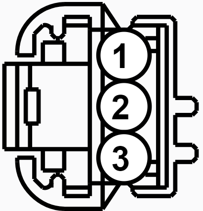
-
From the 2013 Edge Workshop Manual... Pinpoint Test AH: The Outside Air Temperature Display Is Inoperative/Incorrect Refer to Wiring Diagrams Cell 60, Instrument Cluster for schematic and connector information. Normal Operation The ambient air temperature sensor is hardwired to the PCM through separate input and return circuits. The PCM provides a reference voltage to the ambient air temperature sensor and monitors the change in voltage resulting from changes in resistance as determined by outside air temperature. The PCM then messages the ambient air temperature data to the HVAC module, which then filters the temperature data and sends the updated temperature status through the Body Control Module (BCM) over the High Speed Controller Area Network (HS-CAN) . The BCM in turn messages the ambient temperature data in degrees Celsius (metric) to the Instrument Panel Cluster (IPC) over the HS-CAN . When the Fahrenheit (English) display is selected by the driver, the IPC converts the Celsius to Fahrenheit and displays the temperature in the message center. The HVAC module is programmed to update the messaged outside temperature data at different rates depending on several criteria to prevent false temperature displays due to a condition known as heat soaking. Heat soaking is where the outside air temperature is hotter in the location of the Ambient Air Temperature (AAT) sensor than the actual outside air temperature. When the sensed outside temperature rises, the display updates slowly at varying rates based on vehicle speed. When the sensed outside temperature drops, the display updates more quickly basically following the drop experienced by the AAT sensor. This pinpoint test is intended to diagnose the following: Communication concern PCM concern PINPOINT TEST AH : THE OUTSIDE AIR TEMPERATURE DISPLAY IS INOPERATIVE/INCORRECT NOTICE: Use the correct probe adapter(s) when making measurements. Failure to use the correct probe adapter(s) may damage the connector. AH1 RETRIEVE THE RECORDED DTCS FROM THE IPC SELF-TEST Check for recorded IPC DTCs from the self-test. Are any DTCs recorded? Yes REFER to DTC Charts in this section. No GO to AH2. AH2 RETRIEVE THE RECORDED DTCS FROM THE HVAC MODULE SELF-TEST Check for recorded HVAC module DTCs from the self-test. Are any DTCs recorded? Yes REFER to Section 412-00. No GO to AH3. AH3 RETRIEVE THE RECORDED DTCS FROM THE PCM KOEO SELF-TEST Check for recorded PCM DTCs from the Key ON Engine OFF (KOEO) self-test. Are any ambient temperature sensor DTCs recorded? Yes REFER to the Powertrain Control/Emissions Diagnosis (PC/ED) manual. No GO to AH4. AH4 CHECK THE OUTSIDE AIR TEMPERATURE CONCERN Verify the customer outside air temperature display concern. Is the outside air temperature display concern for an incorrect temperature display? Yes GO to AH5. No If the display is inoperative, INSTALL a new HVAC module. REFER to Section 412-00 AH5 CHECK THE AMBIENT AIR TEMPERATURE INPUT TO THE PCM Using an infrared temperature scanner or similar tool, measure and record the temperature of the ambient air temperature sensor body. Ignition ON. Using a diagnostic scan tool, view the Parameter Identifications (PIDs). Select the ambient air temperature (AAT). Monitor the ambient air temperature and compare the value with the recorded temperature of the ambient air temperature sensor body. Does the ambient air temperature match the recorded ambient air temperature sensor measurement within +/- 3° C (+/- 5° F)? Yes GO to AH6. No GO to AH7. AH6 CHECK THE OUTSIDE AIR TEMPERATURE DISPLAY UPDATE Drive the vehicle above 33 km/h (20 mph) 1 to allow the outside air temperature display to update. Did the outside air temperature display update toward the actual ambient air temperature? Yes The system is operating correctly at this time. Explain to the customer the operation of the system as it relates to the update strategy. No INSTALL a new HVAC module. REFER to Section 412-00. AH7 CHECK THE OUTSIDE AIR TEMPERATURE (AAT) SENSOR AT THE PCM Ignition OFF. Disconnect: PCM C1381B (2.0L Engine) . Disconnect: PCM C175B (3.5L and 3.7L Engines) . Disconnect: PCM C175E (3.5L and 3.7L Engines) . For the 2.0L engine, measure the resistance between the PCM C1381B-35, circuit VH407 (VT/GN), harness side and the PCM C1381B-21, circuit RE407 (YE/VT), harness side. For the 3.5L and 3.7L engines, measure the resistance between the PCM C175E-29, circuit VE470 (VT/GY), harness side and the PCM C175B-56, circuit RE407 (YE/VT), harness side. Compare the resistance reading with the ambient temperature using the following table. Outside Air Temperature Ambient Air Temperature Sensor Value Celcius Fahrenheit Resistance (K Ohms) -1.1° to 4.4° 30° to 40° 27.49 to 33.47 4.4° to 10° 40° to 50° 22.06 to 28.86 10° to 15.6° 50° to 60° 16.63 to 23.10 15.6° to 21.1° 60° to 70° 11.74 to 17.32 21.1° to 26.7° 70° to 80° 9.34 to 12.14 26.7° to 32.2° 80° to 90° 8.49 to 9.62 32.2° to 37.8° 90° to 100° 5.93 to 7.87 37.8° to 43.3° 100° to 110° 5.93 to 7.87 Does the resistance match the table specifications above? Yes GO to AH9. No GO to AH8. AH8 CHECK THE AMBIENT AIR TEMPERATURE SENSOR RESISTANCE AT THE AMBIENT AIR TEMPERATURE SENSOR Disconnect: Ambient Air Temperature Sensor C198 . Measure the resistance between the ambient air temperature sensor C198-1, circuit VH407 (YE/GN), component side and the ambient air temperature sensor C198-2, circuit RE407 (YE/VT), component side. Outside Air Temperature Ambient Air Temperature Sensor Value Celcius Fahrenheit Resistance (K Ohms) -1.1° to 4.4° 30° to 40° 27.49 to 33.47 4.4° to 10° 40° to 50° 22.06 to 28.86 10° to 15.6° 50° to 60° 16.63 to 23.10 15.6° to 21.1° 60° to 70° 11.74 to 17.32 21.1° to 26.7° 70° to 80° 9.34 to 12.14 26.7° to 32.2° 80° to 90° 8.49 to 9.62 32.2° to 37.8° 90° to 100° 5.93 to 7.87 37.8° to 43.3° 100° to 110° 5.93 to 7.87 Does the resistance match the table specifications above? Yes The ambient air temperature sensor is operating correctly. REPAIR the circuits for high circuit resistance. No GO to AH10. AH9 CHECK THE AMBIENT AIR TEMPERATURE (AAT) SENSOR FOR OBSTRUCTIONS OR DEBRIS Check the area around the Ambient Air Temperature (AAT) sensor for any obstructions or debris such as leaves or paper. Is the area around the Ambient Air Temperature (AAT) sensor free from any obstructions or debris? Yes GO to AH10. No CLEAR all debris or obstructions as necessary to allow for the free flow of air around the Ambient Air Temperature (AAT) sensor. AH10 CHECK THE AMBIENT AIR TEMPERATURE (AAT) SENSOR OPERATION Disconnect Ambient Air Temperature (AAT) Sensor C198 . Inspect the connector and wiring: water intrusion corrosion damaged pins pushed-out pins Are there any signs of water intrusion, corrosion, damaged or pushed out pins? Yes REPAIR the Ambient Air Temperature (AAT) sensor connector or wiring for any water intrusion, corrosion, damaged or pushed out pins. No INSTALL a new ambient air temperature sensor. Additional documents available via PDF download links... Ambient Air Temperature Sensor Wiring Diagram - Cell 60 Page 4 -2013 Ford Edge Workshop Manual.pdf 2.0L EcoBoost Engine - Powertrain Control Manual (PCM) Connector C1381B Details - 2013 Edge Workshop Manual.pdf 2.0L EcoBoost Engine - Powertrain Control Manual (PCM) Connector C1381B Location - 2013 Edge Workshop Manual.pdf 3.5L & 3.7L Engines - Powertrain Control Manual (PCM) Connector C175B Details - 2013 Edge Workshop Manual.pdf 3.5L & 3.7L Engines - Powertrain Control Manual (PCM) Connector C175B Location - 2013 Edge Workshop Manual.pdf 3.5L & 3.7L Engines - Powertrain Control Manual (PCM) Connector C175E Details - 2013 Edge Workshop Manual.pdf 3.5L & 3.7L Engines - Powertrain Control Manual (PCM) Connector C175E Location (10) - 2013 Edge Workshop Manual.pdf 3.5L & 3.7L Engines - Powertrain Control Manual (PCM) Connector C175E Location (4) - 2013 Edge Workshop Manual.pdf Ambient Air Temperature Sensor - Connector C198 Details -2013 Ford Edge Workshop Manual.pdf Ambient Air Temperature Sensor - Connector C198 Location -2013 Ford Edge Workshop Manual.pdf Ambient Air Temperature Sensor - Removal and Installation - 2013 Ford Edge Workshop Manual.pdf Bumper — Exploded View, Front -2013 Edge Workshop Manual.pdfBumper Cover — Front - Removal and Installation - 2013 Ford Edge Workshop Manual.pdf 2.0L EcoBoost Engine - Powertrain Control Manual (PCM) - Removal and Installation - 2013 Edge Workshop Manual.pdf Good luck!
-
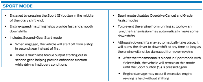
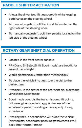
A Ford resource for dealership sales representatives offers this description of 8-speed transmission features... The 2022 Edge Workshop Manual describes the Edge ST transmission this way... This automatic transmission is a 8-speed transmission with electronic shift control. This transmission may also be described as a 7-speed transmission. For the 7-speed applications, 2nd gear is not utilized. Good luck!
-
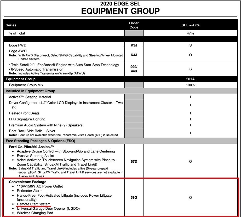
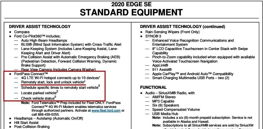
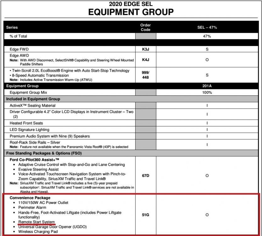
The 2020 Edge Order Guide shows FordPass phone app starting capability as standard on Edge SE, and your experience confirms that availability on your SEL also... On SEL, the Intelligent Access key Remote Start is part of the optional Convenience Package... 2020 Ford Edge Order Guide.pdf (Download Link) Several discussions here by Forum members detail their successful adding of IA key Remote Start, and they can no doubt offer guidance on possible hardware additions and Forscan programming. Good luck!
-
The last OASIS Broadcast Message provides September 2022 target for software patch and OTA deployment for FordPass-connected vehicles, Dealer service bay for others... Jun 17 2022 2021 Edge - Front Camera Inoperative After Vehicle Traveled Over 6MPH (10Km/h) Some 2021 Edge vehicles may exhibit the front camera not turning back on if thecamera system button is pressed once the vehicle is below the speed threshold of 6MPH (10km/h). This may be due to the accessory protocol interface module (APIM) software. Inform customers that engineering is currently working on a solution for this condition and will be released via an over the air (OTA) software update, expected in September 2022. Software will update automatically if the vehicle is connected to FordPass. Monitor OASIS for additional information. Schedule a service appointment for customers that are not connected to FordPass once the repair becomes available. September is not too far off. I'll post here immediately after I see any notice of the corrective update's availability. Good luck!
-
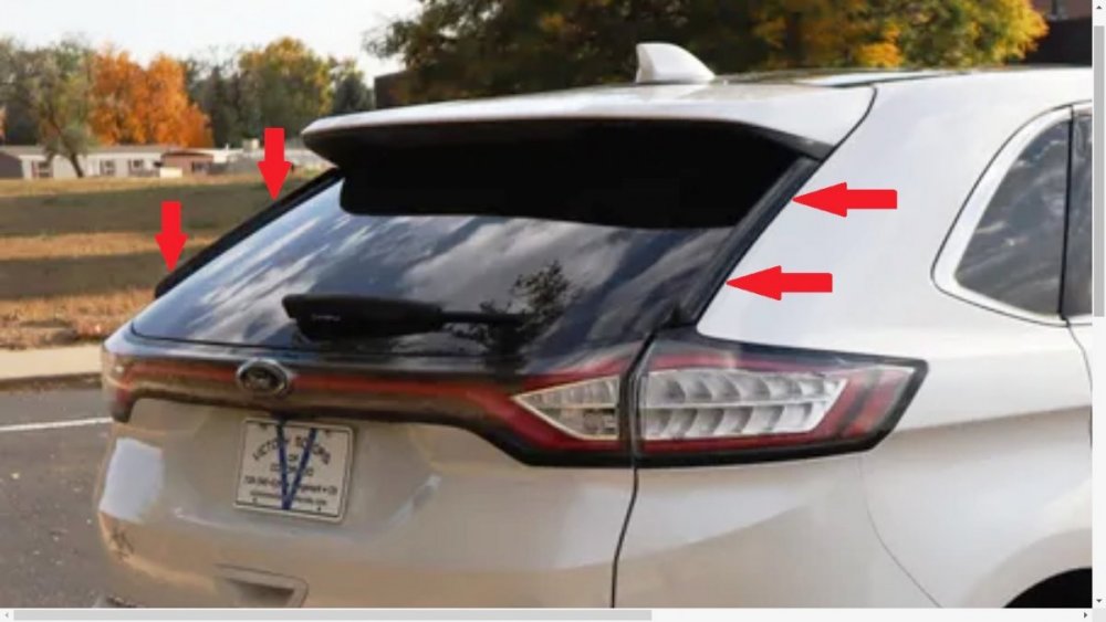
2015-2018 Edge SEL rear liftgate glass plastic black trim
Haz replied to rheld68's topic in Exterior & Body
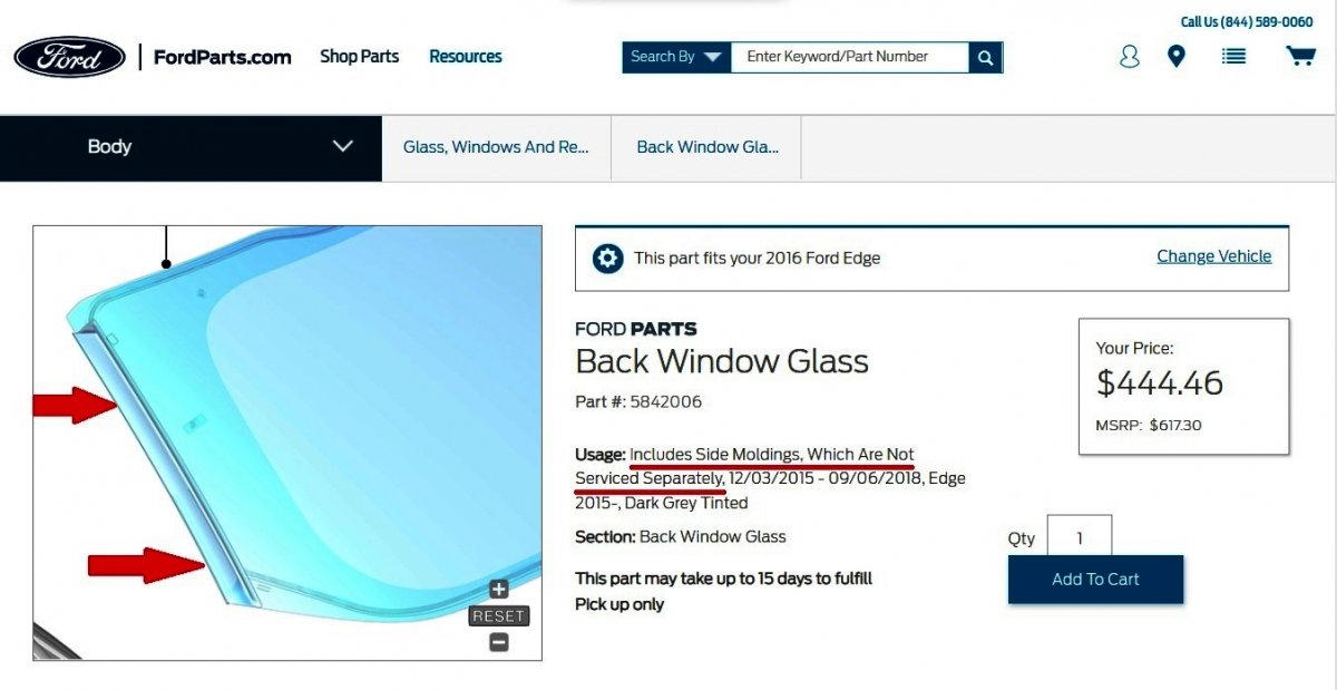
The back glass listing on Ford's parts site indicates the flying buttress side moldings are not available separate from the glass assembly... It may be worth checking used-parts yards in your area to see if an Edge with rear damage/broken liftgate glass is available for you to remove its left side flying buttress molding. The residue on your Edge's rear glass may give you an idea how easily the molding may be removed and/or re-applied. A hacksaw or wire-blade hand saw might work nicely, using the glass surface as a bottom cutting-guide. Car-Parts.com is one online search site that may be helpful to you. Listings typically include photos of the salvage vehicle that would allow you to assess the existing rear glass side molding(s). Good luck!
-
Below are relevant sections of the 2010 Edge Workshop Manual as PDF download links... Anti-Theft — Passive Anti-Theft System (PATS) - Description and Operation - 2010 Edge Workshop Manual.pdf Anti-Theft — Passive Anti-Theft System (PATS) - Diagnosis and Testing - 2010 Edge Workshop Manual.pdf Anti-Theft — Passive Anti-Theft System (PATS) - Parameter Reset - 2010 Edge Workshop Manual.pdf Anti-Theft — Passive Anti-Theft System (PATS) - Anti-Theft Security Access - 2010 Edge Workshop Manual.pdf Anti-Theft — Passive Anti-Theft System (PATS) - Key Programming Switch State Control - 2010 Edge Workshop Manual.pdf Anti-Theft — Passive Anti-Theft System (PATS) - Key Programming Using Two Programmed Keys - 2010 Edge Workshop Manual.pdf Anti-Theft — Passive Anti-Theft System (PATS) - Integrated Keyhead Transmitter (IKT) Key Programming Using Diagnostic Equipment - 2010 Edge Workshop Manual.pdf Anti-Theft — Passive Anti-Theft System (PATS) - Passive Anti-Theft System (PATS) Transceiver Removal and Installation - 2010 Edge Workshop Manual.pdf Anti-Theft — Passive Anti-Theft System (PATS) - Passive Anti-Theft System (PATS) Transceiver Connector C252 Location Illustration - 2010 Edge Workshop Manual.pdf Anti-Theft — Passive Anti-Theft System (PATS) - Passive Anti-Theft System (PATS) Transceiver Connector C252 Details - 2010 Edge Workshop Manual.pdf Instrument Cluster (IC) - Description and Operation - 2010 Edge Workshop Manual.pdf Instrument Cluster (IC) - Removal and Installation - 2010 Edge Workshop Manual.pdf Instrument Cluster (IC) - Connector C220 Location Illustration - 2010 Edge Workshop Manual.pdf Instrument Cluster (IC) - Connector C220 Details - 2010 Edge Workshop Manual.pdf Communications Network - Description and Operation - 2010 Edge Workshop Manual.pdf File attachment limitations prevent me from including a 139-page Communication Network diagnostic document, so I have sent you an alternate-source download link via the Forum Message system. Good luck!
-
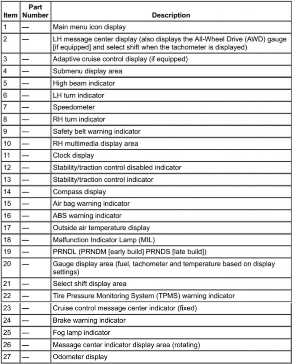
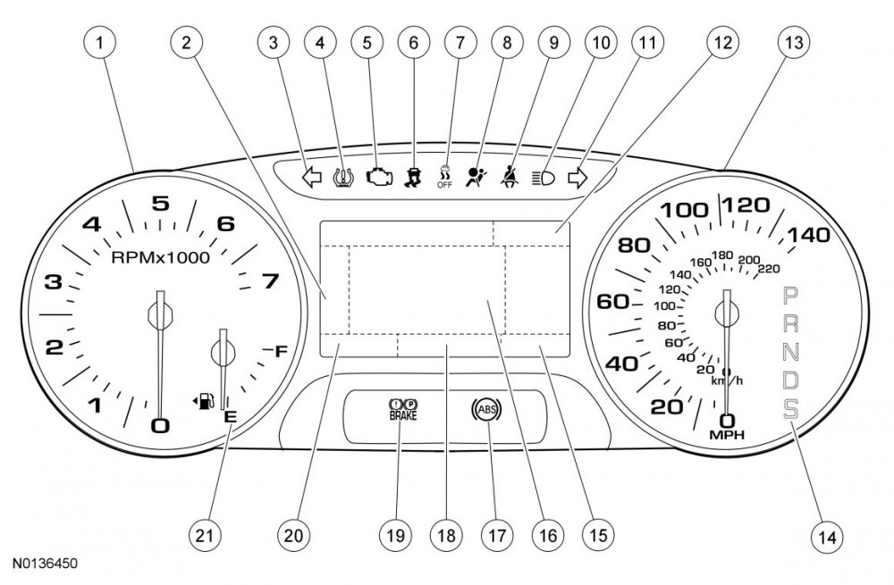
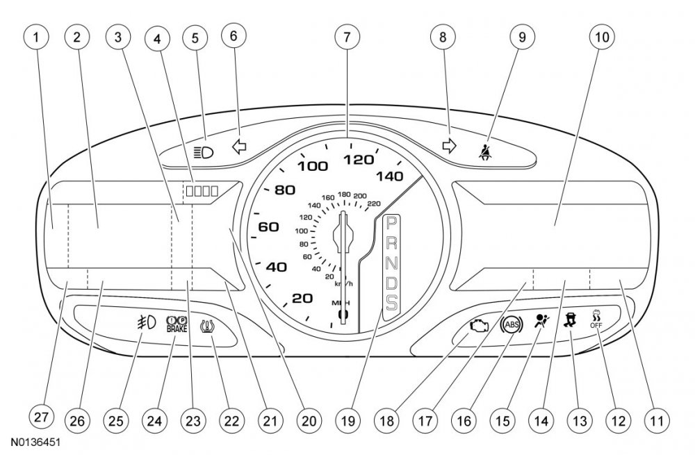
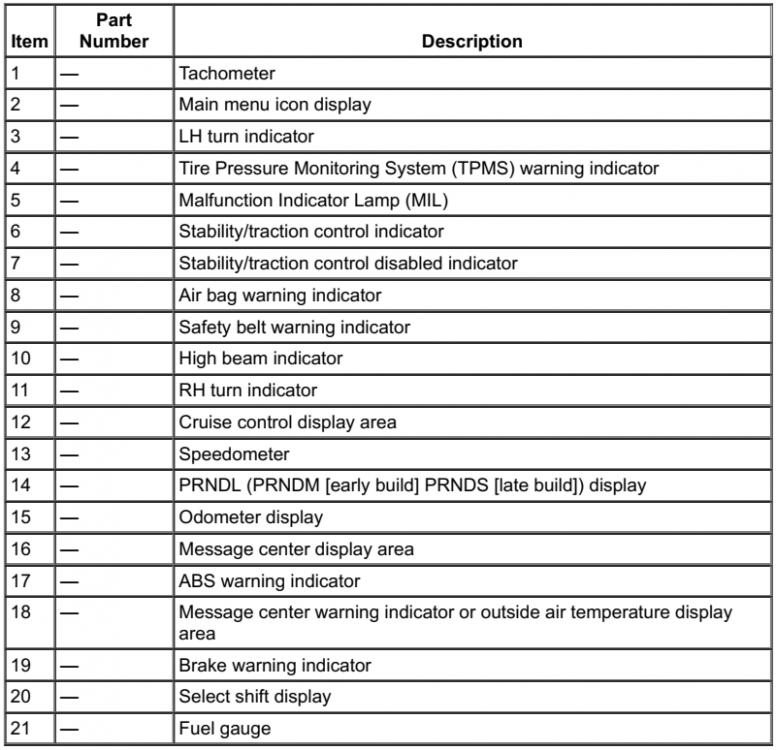
From the 2013 Edge/MKX Workshop Manual... Edge Base Instrument Panel Cluster (IPC) Edge Optional IPC and MKX NOTE: Edge IPC shown, MKX IPC similar Startup (Welcome)/Shutdown (Farewell) Mode The IPC provides a startup/shutdown mode also known as a welcome/farewell strategy. When the vehicle receives a Remote Keyless Entry (RKE) request or a door ajar (open) message, the IPC gradually increases illumination of the gauge trim rings and turns on the message center (the optional IPC provides a welcome graphic). When the key is inserted into the ignition (key off), the IPC illuminates the gauge points. When the ignition is placed into the RUN or START position, the IPC begins a prove-out stage. During the prove-out stage, the IPC provides message center information (replaces the welcome screen with vehicle specific information on the optional IPC ) while illuminating all LED indicators for a predetermined time. For the shutdown, the IPC reverses the startup process. Good luck!

-
“Liftgate Ajar” warning light NOT coming on
Haz replied to Amznwmn's topic in Alarms, Keyless Entry, Locks & Remote Start
Below are PDF download links to relevant sections from the 2013 Edge Workshop Manual... Power Liftgate - Diagnosis and Testing Introduction & Symptom-DTC Charts - 2013 Edge Workshop Manual.pdf Pinpoint Test C - The Power Liftgate Stops in Secondary Latch Position (Does Not Pull into Primary Latch Position).pdf LIFTGATE -TRUNK MODULE (LTM) Wiring Connector C4174B Details.pdf LIFTGATE -TRUNK MODULE (LTM) Wiring Connector C4174B Location Illustration - 2013 Edge Workshop Manual.pdf LIFTGATE LATCH-UNLATCH ASSEMBLY Wiring Connector C4339 Details - 2013 Edge Workshop Manual.pdf LIFTGATE LATCH-UNLATCH ASSEMBLY Wiring Connector C4339 Location Illustration - 2013 Edge Workshop Manual.pdf Power Liftgate Wiring Diagram - Page 1 - 2013 Edge Workshop Manual.pdf Power Liftgate Wiring Diagram - Page 2 - 2013 Edge Workshop Manual.pdf Power Liftgate Wiring Diagram - Page 3 - 2013 Edge Workshop Manual.pdf Power Liftgate Wiring Diagram - Page 4 - 2013 Edge Workshop Manual.pdf Power Liftgate Wiring Diagram - Page 5 - 2013 Edge Workshop Manual.pdf Power Liftgate Initialization - General Procedures - 2013 Edge Workshop Manual.pdf Liftgate Trim Panel - Removal and Installation - 2013 Edge Workshop Manual.pdf Power Liftgate Latch - Removal and Installation - 2013 Edge Workshop Manual.pdf Scuff Plate Trim Panel — Rear - Removal and Installation - 2013 Edge Workshop Manual.pdf Quarter Trim Panel - Removal and Installation - 2013 Edge Workshop Manual.pdf Liftgate-Trunk Module (LTM) - Removal and Installation - 2013 Edge Workshop Manual.pdf Power Liftgate Motor - Removal and Installation - 2013 Edge Workshop Manual.pdf If your scan tool or Forscan reveals DTCs other than those shown in Pinpoint Test C, let me know and I'll provide the appropriate Pinpoint Test and wiring connector info. Good luck! -
Wheel-Size's website provides dimensional data for all factory Edge wheels by model year. You will find that the bolt circles for 2010 & 2013 are identical, but the center bore of the 2013 wheel is smaller than the 2010 wheel. You may find this past discussion on 2010 Edge wheel options to be especially helpful, coupled with Wheel-Size's Mustang wheel reference page. Good luck!
-
Fill Up Issues and Trip Display Needs Tweak
Haz replied to Dr. Evil's topic in Accessories & Modifications
The 2020 Edge Workshop Manual offers descriptions of Dealer Test Mode / Engineering Test Mode, analog fuel gauge operation, and an informative introduction to a diagnostic Pinpoint Test relating to incorrect or fluctuating Distance To Empty values... ============== Dealer Test Mode NOTE: The table lists the displays as they appear when navigating using the down arrow button. To enter the IPC engineering test mode or dealer test mode, begin with the ignition OFF. Press and hold the LH steering wheel switch OK button. Place the ignition ON and continue to hold the button for 5-8 seconds until the display indicates Test or Gauge Sweep. Press the up or down arrow buttons to navigate through each of the display windows. To exit the IPC dealer test mode, press and hold the OK button for 5-8 seconds or place the ignition in OFF. Each down arrow button press advances the viewing window to the next set of items. IPC Display Description Engineering Test Mode Use Right Up/Down to scroll screens Initial entry display into the dealer test mode. ANALOG GAUGE TEST Carries out the gauge sweep of the analog gauges. When the sweep (zero to maximum then return to zero) is complete, the actual data is displayed. TELLTALE AND COLOR TEST Illuminates all cluster microprocessor controlled LED telltales or indicators. Also displays a color palette of boxes below the title. PartNo: xxxx-xx Core: xxxx-xx Cal#1: xxxx-xx ECU S/W: xxxx-xx Displays the IPC part number information. Man Date: xxxxxx B&A Config Bytes xx xx xx xx xx xx xx xx xx xx Displays the manufacturing information. Date in the format of YYMMDD. B&A configuration bytes DTC: HIST CURR xxxxxx x x xxxxxx x x Displays all of the Diagnostic Trouble Codes (DTCs) set (history and current Diagnostic Trouble Codes [DTCs]). An X in the HIST or CURR column means the DTC is active. Three Diagnostic Trouble Codes (DTCs) display on each screen. If more Diagnostic Trouble Codes (DTCs) are present, there will be additional screens listing them. If there are no Diagnostic Trouble Codes (DTCs) in history or current, the display will only be the title row. Vehicle Speed: xxx.x km/h xxx.x MPH Tach: xxxx RPM NOTE: These are the filtered values used to drive the gauge positions, not the actual positions. Displays the digital representation of the speedometer gauge in mph and km/h. Inst Fuel: xxxx FLPM: xxxx.xx Displays the instant fuel level and filtered fuel level in percent. This is used for a single sender fuel level input. Inst Fuel1: xxxx FLPM: xxxx.xx Displays the instant fuel level and filtered fuel level in percent. This is used for the fuel pump assembly input on a dual sender fuel tank configuration. Inst Fuel2: xxxx FLPM: xxxx.xx Displays the instant fuel level and filtered fuel level in percent. This is used for the fuel level sensor input on a dual sender fuel tank configuration. DTE: Inst 01 Disp km xxx xxx xxx mi xxx xxx xxx Displays the values used for calculating the DTE function. RAFE RAFE_01 xxx.x xxx.x 1/100km xxx.x xxx.x MPG xxx.x xxx.x km/l Displays the running average fuel economy. The values are derived from the DTE function. State Val #ofVS Szero: xxxx xxxx Off: xxxx xxxx On: xxxx xxxx Displays the key ON initialization, key OFF reference, and zero speed reference fuel level values in fuel level for a single sender fuel level input. State Val #ofVS Szero1: xxxx xxxx Off: xxxx xxxx On: xxxx xxxx Displays the key ON initialization, key OFF reference, and zero speed reference fuel level values in fuel level for the fuel pump assembly input on a dual sender fuel tank configuration. State Val #ofVS Szero2: xxxx xxxx Off: xxxx xxxx On: xxxx xxxx Displays the key ON initialization, key OFF reference, and zero speed reference fuel level values in fuel level for the fuel level sensor input on a dual sender fuel tank configuration. Coolant Temp (°C): xxx Displays the digital representation of the coolant temperature gauge indication in degrees Celsius. Odo cnts: xx Trip A: xxxxx.x km Trip A: xxxxx.x mi Displays the values from the odometer count signal and the trip A statistics. Odo cnts: xx Trip B: xxxxx.x km Trip B: xxxxx.x mi Displays the values from the odometer count signal and the trip B statistics. Fuel cnts: xxx Fuel A: xxxxx.x l Fuel A: xxxxx.x g Displays the values of the fuel flow display signal from the PCM and the approximate fuel used for the trip stats A. Fuel cnts: xxx Fuel B: xxxxx.x l Fuel B: xxxxx.x g Displays the values of the fuel flow display signal from the PCM and the approximate fuel used for the trip stats B. Battery: xx.xV Compass: xx Last Chime: xx Displays the current battery level. Displays the compass direction. Displays the number of the last chime sounded. Dim Step: xx Dim Gauge: xxxxx Dim Pointer: xxxxx Displays the first screen of dimming information. Dim step is the dimming level. Dim gauge is the internal illumination number for the gauge backlighting (1 to 10,000). Dim pointer is the internal illumination number for the gauge pointer backlighting (1 to 10,000). Dim Step: xx Dim PRNDL: xxxxx Dim Display: xxxxx Displays the second screen of dimming information. Dim step is dimming level. Dim PRNDL is the internal illumination number for PRNDL backlighting (1 to 10,000). Dim display is the internal illumination number for the display backlighting (1 to 10,000). PDS: x LWS: x Park detect switch (0 = open/not park, 1 = closed/park). Engineering Test Mode Use Right Up/Down to scroll screens Repeats the test display cycle. ============ Analog Gauges Fuel Gauge The IPC sends a reference voltage to the fuel level sender(s). As the fuel level changes, a float actuates the variable resistor fuel level sender, raising or lowering the fuel level signal voltage. The IPC monitors the changes in voltage from both senders and commands the fuel gauge with a corresponding movement of the pointer. After a fuel fill up, the time for the fuel gauge to move from empty (E) to full (F) ranges from 2 seconds to 55 minutes depending on which operating mode the fuel gauge is in. The IPC uses 4 different operating modes to calculate the fuel level: Anti-slosh (default mode) Key OFF fueling Key ON fueling Recovery The default fuel gauge mode is called the anti-slosh mode. To prevent fuel gauge changes from fuel slosh (gauge instability due to changes in fuel sensor readings caused by fuel moving around in the tank), the fuel gauge takes approximately 40 minutes to go from empty (E) to full (F). The key OFF fueling mode (2 seconds to read empty [E] to full [F]) requires 3 conditions to be met: The ignition must be in the OFF mode when refueling the vehicle. At least 6% of the vehicle's fuel capacity must be added to the fuel tank. The IPC must receive a valid ignition ON fuel sensor reading within one second of the ignition being put into the RUN mode. The key ON sample readings are considered valid if the fuel sensor reading is between 10 ohms ± 2 ohms and 180 ohms ± 4 ohms. If these conditions are not met, the fuel gauge stays in the anti-slosh mode, which results in a slow to read full (F) event. The key ON fueling mode (approximately 60 seconds to read empty [E] to full [F]) requires the following conditions be met: The transmission is in PARK (P) or NEUTRAL (N). The ignition is in the RUN mode. At least 6% of the vehicle's fuel capacity must be added to the fuel tank In key ON fueling mode, a 30-second timer activates after the transmission is put into the PARK (P) or NEUTRAL (N) position. When the 30-second time has elapsed and at least 9% of the vehicle's fuel capacity has been added, the fuel gauge response time is 60 seconds to read from empty (E) to full (F). When the transmission is shifted out of PARK (P) or NEUTRAL (N), the fuel gauge strategy reverts to the anti-slosh mode. The key ON fueling mode prevents slow to read full events from happening if the customer refuels the vehicle with the ignition in the RUN mode. Recovery mode is incorporated into the IPC strategy to recover from a missing fuel level input after a refueling event. Missing fuel level inputs result from intermittent opens in the fuel sensor or its circuits. Recovery mode (empty [E] to full [F] approximately 17 minutes) is initiated when the following 2 conditions are met: The IPC is in the anti-slosh (default) mode. The actual fuel level in the tank is 5% different from what is being displayed by the fuel gauge. =============== Fuel Level Sender The fuel level sender is mounted to the fuel pump and sender unit or the fuel level sensor. The fuel level sender is a dual sweep potentiometer style resistor connected to a float mechanism. The dual sweep design provides a second resistance measurement that reduces the intermittent loss of data due to corrosion between the resistor wires and the sweep arm. As the fuel level changes, the float rises or falls with the fuel level moving the sweep arm across the resistor wires. This movement either increases or decreases the resistance through the unit. The fuel level sensor resistance ranges from 180 ohms ± 4 ohms at empty (E) to 10 ohms ± 2 ohms at full (F). When the fuel level is low, the fuel level sensor resistance is high. When the fuel level is high, the fuel level sensor resistance is low. Both the fuel pump and sender unit and fuel level sensor are hardwired to the IPC through separate signal and return circuits. The fuel level return circuits are grounded internally in the IPC . The IPC provides a reference voltage on the fuel level signal circuit. As the fuel level changes, the change in resistance raises or lowers the fuel level signal voltage depending on the resistance of the fuel level sender. ================================== The DTE Display Is Incorrect Or Fluctuates Normal Operation and Fault Conditions NOTE: The DTE display and the fuel gauge both use the fuel level input from the fuel tank to provide their respective functions. If the fuel gauge doesn't function correctly, both the fuel gauge and the DTE display are affected. NOTE: The actual DTE can be higher or lower than the DTE displayed in the message center due to changes in driving conditions. It is important to understand how the DTE is calculated and the factors that impact the DTE display when determining how to address any DTE concerns. The DTE is calculated in the IPC using the Running Average Fuel Economy (RAFE), which is the fuel economy over a much longer distance than the Instantaneous Fuel Economy (IFE), and the fuel level input from the fuel sender(s) to determine how many miles the vehicle can be driven based on the remaining fuel in the tank. NOTE: Even if the fuel economy is relatively constant, the DTE can vary in the short term by up to 50 miles, but is usually within 10 miles. The IPC defaults to a base programmed fuel economy when the battery is initially connected and adjusts upward or downward based on driving habits and conditions. Since the DTE is calculated and averaged over a longer period of time, varying driving conditions can have a significant impact on the current or short term DTE as opposed to the displayed DTE . This difference often leads to customer complaints of incorrect or invalid DTE . The following list provides some (not all) of the driving conditions that may lead to an incorrect or fluctuating DTE concern: Changing between towing/not towing Changing driving between city and highway Allowing the vehicle to idle for long periods of time Using the remote start feature (if equipped) frequently or allowing the vehicle to warm up, particularly when parked on a grade Parking or driving on grades Not using a type of fuel (E85 or non-ethanol based) consistently Over-fueling or not filling the tank completely (partial refueling) To better illustrate the affects of how driving conditions can affect DTE , please refer to the examples below. The example below illustrates how the following observations are normal and expected since the low fuel reminder is triggered from a fuel volume and not from a fixed distance to empty. If while driving, the low fuel reminder (low fuel indicator and low fuel warning message) displays when the DTE equals 94.4 km (59 miles) and the driver adds 11.36 L (3 gallons) of fuel, the new DTE may become 124.8 km (78 miles). After continued driving, the low fuel reminder may now display when the DTE equals 83.2 km (52 miles). The next example (below) illustrates what occurs when idling on an incline. In this example, the customer should be made aware of how the condition will correct after a few minutes of idling on a level surface. If the customer stops and parks the vehicle on an incline in a driveway, then in the morning remote starts the vehicle, allowing the engine to idle, the DTE may now equal 184 km (115 miles). As the customer drives, the low fuel reminder displays when the DTE equals 148.8 km (93 miles). Finally, after 5 more minutes of driving, the DTE is back to 80 km (50 miles). In this example, the fuel gauge and the DTE display can be out of sync, but self-corrects after several minutes of driving. Possible Sources BCM concern Fuel gauge concern Changes in driving conditions such as: towing extended idle times parking on any grades alcohol in the fuel refueling patterns IPC configuration Visual Inspection and Diagnostic Prechecks Make sure to record the Running Average Fuel Economy (RAFE) prior to disconnecting the battery, removing the IPC fuse 13 (7.5A). If any of the previous conditions occur, the vehicle must be driven over time to allow the DTE calculations to adjust. PINPOINT TEST AD: THE DTE (DISTANCE TO EMPTY) DISPLAY IS INCORRECT OR FLUCTUATES AD1 REVIEW AND INVESTIGATE THE FOLLOWING DRIVING CONDITIONS WITH THE CUSTOMER Determine whether the driver changes the following driving conditions: changing between towing/not towing, city/highway driving use of extended idle times use of remote start frequently (if equipped) parking/driving on grades use of E85 fuel exclusively or switching to non-Ethanol fuel over filling the fuel tank or not filling the tank completely (partial refueling) Does the driver change driving conditions? Yes Advise the customer how changing driving conditions can affect the current short-term DTE as opposed to the displayed long-term DTE . Good luck! -
Much gratitude to omar302 -- I blanked-out on the fact that Davidoo has an ST. (Not ST) exclusion added to discussion subject line. Good luck!
-
MooseMate: omar302's images in this recent discussion may be helpful to your dealership... Good luck!
-
Rear Brakes sticking after bleeding with the park brake set
Haz replied to maddog0963's topic in Brakes, Chassis & Suspension
Relating to the DTC you mention, the 2014 Workshop Manual offers this diagnostic Pinpoint Test... Pinpoint Test C - DTCs C0044:28, C0044:49 and C0044:64 Normal Operation The ABS module uses internal pressure sensors to determine proper operation by monitoring internal Hydraulic Control Unit (HCU) hydraulic pressures. These DTCs set if the brake pressure sensor signals do not match. This fault could set by either an internal ABS module failure or a pressure sensor failure. The pressure sensors are internal to the HCU and cannot be serviced separately. Unintentional brake fluid pressure applied when the ABS module is expecting no brake fluid pressure can set this fault. DTC C0044:28 (Brake Pressure Sensor "A": Signal Bias Level Out of Range / Zero Adjustment Failure) — this DTC sets if the brake pressure sensor signals do not match. This fault could set by either an internal ABS module failure or a pressure sensor failure. DTC C0044:49 (Brake Pressure Sensor "A": Internal Electronic Failure) — this DTC sets if the brake pressure sensor signals do not match. This fault could set by either an internal ABS module failure or a pressure sensor failure. DTC C0044:64 (Brake Pressure Sensor "A": Signal Plausibility Failure) — this DTC sets if the brake pressure sensor signals do not match. This fault could set by either an internal ABS module failure or a pressure sensor failure. This pinpoint test is intended to diagnose the following: Brake pedal position switch/bracket ABS module HCU PINPOINT TEST C : DTCS C0044:28, C0044:49 AND C0044:64 C1 CHECK THE BRAKE PEDAL AND BRACKET Inspect the brake pedal position switch and brake pedal assembly. Verify there is no brake pedal pressure unintentionally applied due to incorrect brake pedal position switch or brake pedal installation. Are the brake pedal position switch and brake pedal OK? Yes GO to C2. No REPAIR or INSTALL new components as necessary. REFER to Section 206-06. C2 CHECK FOR DTCS C0044:28, C0044:49 AND C0044:64 TO RETURN Ignition ON. Using a scan tool, clear all CMDTCs . Test drive the vehicle at speeds greater than 32 km/h (20 mph). Enter the following diagnostic mode on the scan tool: Self-Test — ABS Module . Are DTCs C0044:28, C0044:49 and C0044:64 present? Yes GO to C3. No The system is operating correctly at this time. The concern may have been caused by air trapped in the hydraulic brake system. CLEAR the DTCs. REPEAT the self-test. C3 CHECK FOR CORRECT ABS MODULE TO HCU TORQUE VALUES Verify all ABS module-to-HCU fasteners are tightened to their correct torque specifications. Are the ABS module to HCU fasteners correctly torqued? Yes For vehicles without adaptive cruise control, INSTALL an ABS module. REFER to Anti-Lock Brake System (ABS) Module in this section. GO to C4. For vehicles with adaptive cruise control, INSTALL a new HCU . REFER to Hydraulic Control Unit (HCU) in this section. TEST the system for normal operation. No TIGHTEN all ABS module-to-HCU fasteners. CLEAR the DTCs. GO to C4. C4 CHECK FOR DTCS C0044:28, C0044:49 AND C0044:64 Test drive the vehicle at speeds greater than 32 km/h (20 mph). Enter the following diagnostic mode on the scan tool: Self-Test — ABS Module . Carry out the ABS module self-test. Are DTCs C0044:28, C0044:49 and C0044:64 present? Yes INSTALL a new HCU . REFER to Hydraulic Control Unit (HCU) in this section. TEST the system for normal operation. No Repairs complete. The system is operating correctly at this time. ...and relating to the above-mentioned torque specs... Torque Specifications Description Nm lb-ft lb-in ABS module screws 2 — 18 Brake caliper brake tube-to-Hydraulic Control Unit (HCU) fittings 20 — 177 Front wheel speed sensor bolts 7 — 62 HCU bracket-to-frame bolts 25 18 — HCU bracket-to-HCU bolt 11 — 97 Master cylinder brake tube-to-HCU fittings 28 21 — Rear wheel speed sensor bolts 9 — 80 Additional relevant Workshop Manual sections are below as PDF download links... Brake System Component Tests - 2014 Edge Workshop Manual.pdf Brake System Bleeding Procedure - 2014 Edge Workshop Manual.pdf Component Bleeding Procedure - 2014 Edge Workshop Manual.pdf Hydraulic Control Unit (HCU) Removal and Installation - 2014 Edge Workshop Manual.pdf? You mention you could not get the ABS Service Bleed to work, presumably with your scan tool. Do you have Forscan capability? Try searching YouTube where many 'Ford ABS Service Bleed using Forscan' videos are available, or try searching the same procedure for your specific brand/model scan tool. Good luck! -
If you sense transmission slippage, it would be worth you having your dealership's Service Advisor and/or Transmission Technician test drive it. This could be a costly repair that I expect you would be very happy to not pay for after your Edge's warranty expires. I presume the 5,000 miles means the slippage caused by these damaged seals presents itself early in the vehicle's usage and that it requires this repair to eliminate the slippage. If it's truly slipping, you already have a problem that the properly trained transmission tech can correct. This Special Service Message was just released by Ford via the Professional Technician System website as an OASIS Message, so you may need to explain it to them... Good luck!
-
“Liftgate Ajar” warning light NOT coming on
Haz replied to Amznwmn's topic in Alarms, Keyless Entry, Locks & Remote Start
Switches in the Liftgate Latch indicate the latched/unlatched condition to the Rear Gate Trunk Module (RTGM), which communicates an Ajar condition to the Body Control Module (BCM), which sets the Liftgate Ajar warning in the gauge cluster Message Center and sounds the warning chime. Diagnostic Trouble Codes (DTCs) may exist in your Edge's electronic modules which specify diagnostic procedures to assess whether wiring, the latch assembly, or the RTGM may be causing the problem. Do you have code-scanning/Forscan capability and a multi-meter to perform wiring and module diagnostics -- or -- are you likely to turn this job over to a dealership technician? If you're technically capable, or have a friend/relative who is, I can provide wiring diagrams, electrical connector details, module locations, removal & installation procedures for involved components, and the Pinpoint Test diagnostic guidance -- after you tell us your Edge's model year. Otherwise, a dealership technician can easily perform the diagnostics and make certain the faulty component is repaired or replaced. Good luck! -
SSM 51011 Various Vehicles - 8F35 - Transmission Slip On Acceleration From A Stop When Hot Less Than 5,000 Miles (8,000 Km) - Built On Or Before 16-Mar-2022 Some 2018-2022 Ford and Lincoln vehicles equipped with the 8F35 transmission built on or before 16-Mar-2022 may exhibit transmission slip during acceleration from a stop when hot. This may be due damaged internal case half pump seals (7N265). To correct the condition, remove the transmission and replace the internal case half pump seals. Refer to Workshop Manual (WSM), Section 307-01.
-
On August 1, 2022, Ford issued Special Service Message 50982 to dealership Service Department personnel, acknowledging various 2018-2022 models have a charging pad incompatibility with iPhone 12/13/Magsafe technology hardware, and recommending that owners employ USB cabling to charge these phones while in their affected Ford & Lincoln vehicles. Good luck!
-
The following diagnostic routine relating to DTC C0020:13 is from the 2012 Edge Workshop Manual: Pinpoint Tests Pinpoint Test A: DTCs C0020:13, C0020:71 Refer to Wiring Diagrams Cell 42, Vehicle Dynamic Systems for schematic and connector information. Normal Operation The ABS module uses an internal solid state switch to operate the ABS pump motor. The ABS module tests the ABS pump motor by activating it for 30 milliseconds. While the pump motor is being activated, the ABS module monitors the voltage drop across the ABS pump motor solid state switch and the amount of current the ABS pump motor draws through the solid state switch. If the voltage drop is too high or if the ABS pump motor is drawing too much current, the ABS module sets a DTC. After 30 milliseconds have passed, the ABS module stops applying voltage to the pump motor and observes the voltage that the spinning ABS pump motor is generating. The voltage generated by the motor indicates how fast the motor is spinning. Voltage that is too low indicates the motor is not spinning freely and a DTC sets. Fused battery voltage from Battery Junction Box (BJB) fuse 5 (40A) is used by the ABS module to power the ABS pump motor. The ABS module provides ground for the ABS pump motor. Insufficient power or ground along these circuits causes multiple DTCs to set. C0020:13 (ABS Pump Motor Control: Circuit Open) — this DTC sets if the voltage supplied to the ABS module is less than 10 volts, if there is an open or high resistance on the ABS pump motor circuit between the ABS module and the Hydraulic Control Unit (HCU) , or if the ABS module is faulted internally. C0020:71 (ABS Pump Motor Control: Actuator Stuck) — this DTC sets if the ABS module detects the ABS pump motor is not rotating when it is commanded to run. This pinpoint test is intended to diagnose the following: Fuse Wiring, terminals or connectors HCU ABS module PINPOINT TEST A : DTCS C0020:13 AND C0020:71 NOTICE: Use the correct probe adapter(s) when making measurements. Failure to use the correct probe adapter(s) may damage the connector. NOTE: Failure to disconnect the battery when instructed results in false resistance readings. Refer to Section 414-01. A1 CHECK THE PUMP MOTOR (PMP_MOTOR) ACTIVE COMMAND Connect the scan tool. Ignition ON. Enter the following diagnostic mode on the scan tool: DataLogger — ABS Module . Toggle the PMP_MOTOR active command ON. Listen for the ABS pump motor noise, does the ABS pump motor run for approximately 2 seconds? Yes GO to A2. No TOGGLE the PMP_MOTOR active command OFF. GO to A3. A2 CHECK FOR FAULT REPEATABILITY Clear the ABS module DTCs. Drive the vehicle at speeds greater than 20 km/h (12 mph). Bring the vehicle to a safe stop. Enter the following diagnostic mode on the scan tool: Self-Test — ABS Module . Are DTCs C0020:13 or C0020:71 retrieved? Yes GO to A3. No If any other DTCs are present, REFER to the ABS Module DTC Chart in this section. If no DTCs are present, the system is operating correctly at this time. A3 CHECK THE ABS MODULE GROUND EYELET AT THE CHASSIS Ignition OFF. Remove the bolt retaining G103 near the battery. Clean the body mating surface and ground eyelets. Install the ground eyelet to the chassis with the retaining bolt. Ignition ON. Enter the following diagnostic mode on the scan tool: Self-Test — ABS Module . Is the concern still present? Yes GO to A4. No The concern was caused by a loose or corroded connector. CLEAR the DTCs. REPEAT self-test. A4 CHECK THE PUMP MOTOR VOLTAGE SUPPLY TO THE ABS MODULE Ignition OFF. Disconnect: ABS Module C135 . Measure the voltage between ABS module C135-1, circuit SBB05 (GY/RD), harness side and ground. Is the voltage greater than 10 volts? Yes GO to A5. No VERIFY that BJB fuse 5 (40A) is OK. If OK, REPAIR circuit SBB05 (GY/RD). If not OK, REFER to the Wiring Diagrams manual to identify the cause of the circuit short. CLEAR the DTCs and REPEAT the self-test. A5 CHECK THE ABS MODULE GROUND CIRCUIT FOR AN OPEN Ignition OFF. Disconnect: Battery Negative Cable . Measure the resistance between ABS module C135-16, circuit GD121 (BK/YE), harness side and ground. Is the resistance less than 5 ohms? Yes GO to A6. No REPAIR circuit GD121 (BK/YE) for an open circuit. CLEAR the DTCs. REPEAT the self-test. A6 CHECK FOR CORRECT ABS MODULE OPERATION Connect: Battery Negative Cable . Check ABS module C135 for: corrosion pushed-out pins spread terminals Connect: ABS Module C135 . Make sure the connector is seated correctly, then operate the system and verify the concern is still present. Is the concern still present? Yes For vehicles without adaptive cruise control, INSTALL a new ABS module. REFER to Anti-Lock Brake System (ABS) Module in this section. TEST the system for normal operation. For vehicles with adaptive cruise control, INSTALL a new HCU . REFER to Hydraulic Control Unit (HCU) in this section. TEST the system for normal operation. No The system is operating correctly at this time. The concern may have been caused by a loose or corroded connector. CLEAR the DTCs. REPEAT the self-test. PDF download links to supporting 2012 Edge Workshop Manual documents... Vehicle Dynamics Wiring Diagram - 2012 Edge Workshop Manual.pdf Anti-Lock Brake System (ABS) Module - Wiring Diagram 1 with BJB Fuses Identified - 2012 Edge Workshop Manual.pdf Anti-Lock Brake System (ABS) Module - Wiring Diagram 2 with BJB Fuses Identified - 2012 Edge Workshop Manual.pdf Anti-Lock Brake System (ABS) Module - Connector C135 Details - 2012 Edge Workshop Manual.pdf G103 ABS Ground Circuit Location - 2012 Edge Workshop Manual.pdf Battery Junction Box Illustration - 2012 Edge Workshop Manual.pdf Battery Junction Box Details - 2012 Edge Workshop Manual.pdf Good luck!


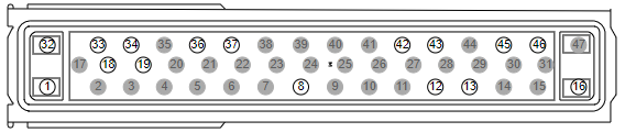
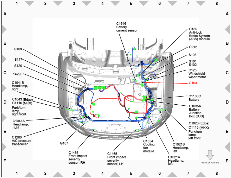
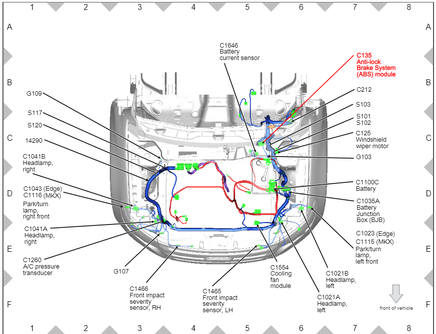
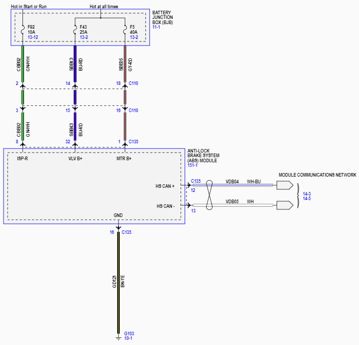
-
Safety Recall 22S43's permanent repair procedure was/is included as PDF download link at bottom of the original post, above, and will also immediately download from here... Safety Recall 22S43 - Technical Info - 07-05-2022.pdf Good luck!
-
Park outdoors: Ford expands recall for possible engine fires
Haz replied to 1004ron's topic in Articles, News & Reviews
1004ron: Your's is a rhetorical question, right? Good luck!