Haz
-
Posts
1,568 -
Joined
-
Last visited
-
Days Won
436
Content Type
Profiles
Forums
Gallery
Everything posted by Haz
-
Just in case you are not familiar with the Timing Adjustment Procedure, below are PDF download links to this procedure and all its supplemental documents, from the 2011 Edge Workshop Manual... Good luck! Roof Opening Panel General Procedures - Timing Adjustment - 2011 Edge Workshop Manual.pdf Roof Opening Panel Removal and Installation - Front Sliding - 2011 Edge Workshop Manual.pdf Roof Opening Panel Motor - Front Sliding Panel - Removal and Installation - 2011 Edge Workshop Manual.pdf Roof Opening Panel Motor - Shade - 2011 Edge Workshop Manual.pdf Roof Opening Panel Motor Initialization - 2011 Edge Workshop Manual.pdf
-
Heated/cooled seat stopped working 2016 Edge sport B272C
Haz replied to 68lemans462's topic in 2016 Edge & MKX
The following description is from the 2016 Edge Workshop Manual, edited to provide specifics on climate controlled seats, followed by an explanation of the DTC your Edge is exhibiting... Climate Controlled Seats This system allows on-demand, independent, electrical heating/cooling of each front seat. The climate controlled seat system consists of the following components: Blower motor, located within each front seat cushion and backrest Air filter, integrated to each blower motor assembly (not serviceable) Climate-controlled seat buttons, located on the FDIM (touchscreen) FCIM SCME , mounted to the bottom of the front passenger seat Cushion and backrest manifolds Cushion and backrest foam pads Cushion and backrest trim covers Climate Controlled Seat Operation The driver and passenger climate controlled seat buttons are selected from the FCIM and FDIM (touchscreen). The climate controlled seat system functions independently from the vehicle's climate control system. The seat cushion and backrest are each equipped with a blower motor assembly. As cabin air is drawn through each blower motor, a Thermo-Electric Device (TED) heats or cools the air, which is then directed into the foam pad where it is distributed along the surface of the cushion and backrest of the seat. Once the system is activated, the SCME uses a set of flexible algorithms to control the heating/cooling modes and the blower speed dependant on the commanded climate controlled seat settings. The SCME monitors seat cushion temperature while it supplies voltage and ground to both blower motors. The SCME also supplies a variable voltage signal to control the blower speed. Cabin air enters the blower through an integrated filter attached to the blower motor housing. Heated or cooled air exits the blower motor and flows through the foam pad. Climate Controlled Seat Cooling Characteristics In cool mode, the blower motors can remove up to 8° C (14° F) from the ambient air temperature entering the system. The system control settings are based on the 3 indicators next to each climate controlled seat cool switch button on the touchscreen. The first setting is HIGH (3 indicators), the second setting is MED (2 indicators) and the third is LOW (1 indicator) then OFF (no indicators). When cooling, the SCME maintains a constant blower motor speed and a constant Thermo-Electric Device (TED) supply voltage (duty cycle is determined by the switch setting) in COOL mode. Climate Controlled Seat Cooling Characteristics In cool mode, the blower motors can remove up to 8° C (14° F) from the ambient air temperature entering the system. The system control settings are based on the 3 indicators next to each climate controlled seat cool switch button on the touchscreen. The first setting is HIGH (3 indicators), the second setting is MED (2 indicators) and the third is LOW (1 indicator) then OFF (no indicators). When cooling, the SCME maintains a constant blower motor speed and a constant Thermo-Electric Device (TED) supply voltage (duty cycle is determined by the switch setting) in COOL mode. Climate Controlled Seat Recovery Mode NOTE: The presence of overtemperature faults (Diagnostic Trouble Codes (DTCs) B2729, B2730, B272A and B272B) can be induced by incorrectly operating the climate controlled seat system after an initial heat setting has been attained. If a heat setting is repeatedly turned off and on in an attempt to increase the seat temperature or repeatedly toggled between heat and cool modes, an overtemperature condition can result and the Diagnostic Trouble Codes (DTCs) may be set. If the temperature of one of the blower motors rises above 110° C (229.8° F) in the heat mode or 65° C (148.9° F) in the cool mode for more than 4 seconds, the SCME records an overtemperature DTC , removes voltage from the Thermo-Electric Devices (TEDs) (part of the blower motor assembly) and goes into recovery mode (blower only) for 30 seconds to cool down the blower motor. The same occurs if a temperature difference of 60° C (108° F) or greater is detected between the backrest and cushion blower motors on either front seat. The SCME continues to monitor the blower motors while in recovery mode. If the temperature of the Thermo-Electric Devices (TEDs) do not drop to 105° C (220.8° F) in the heat mode or 60° C (139.9° F) in the cool mode after 30 seconds, the system continues to cool the blower motors in recovery mode for up to 5 minutes. If the Thermo-Electric Devices (TEDs) cool down after 30 seconds, but before 5 minutes (checked at 4 second intervals), the system is operating normally. An overtemperature DTC is still recorded even if the system recovers and is operating normally. This is more likely to occur during extreme cabin temperatures with significant seat back sun load. If the system does not recover within 30 seconds in heat mode or within 5 minutes in cool mode, the SCME disables that seat (fault mode) and remains off until the ignition is cycled. Also, if the SCME detects a temperature differential fault twice during the same ignition cycle, the SCME disables the seat. When a fault causes a shutdown, the climate controlled seat indicators turn off and that seat is not operational until the next ignition cycle. Component Description FDIM The FDIM (touchscreen) contains the heated seat (or climate controlled seat) buttons. FCIM The FCIM contains the heated seat (or climate controlled seat) buttons. If equipped with heated seats, the FCIM monitors the seat cushion temperature sensor and supplies heater current to the seat cushion and backrest heater mats until the desired setpoint temperature is reached. Once the setpoint temperature is reached, the FCIM cycles the heater circuits on/off as required to maintain the setpoint temperature. PMI is required when a new FCIM is installed. Heater Mat If equipped with heated seats, the cushion heater mats are each equipped with a temperature sensor (thermistor) which provides feedback to the FCIM . The cushion and backrest heater mats are connected in series. SCME If equipped with climate controlled seats, the SCME controls the operation of the climate controlled seat system. PMI is required when a new SCME is installed. Blower Motor If equipped with climate controlled seats, the seat cushion and backrest are each equipped with a blower motor assembly (Thermo-Electric Device (TED) and fan motor, serviced as an assembly). There is also a temperature sensor (thermistor) in each blower motor which provides feedback to the SCME . The blower motor assembly is controlled by the SCME . +++++++++ DTC B272C Normal Operation and Fault Conditions The SCME is supplied voltage at all times, but the climate controlled seat system only operates with the engine running. The system can be operated with the ignition ON engine OFF by using a scan tool to bypass the climate controlled seat buttons on the touchscreen interface. When commanding a heat or cool mode operation in this manner, the climate controlled seat system only operates in 15 second intervals. Both voltage supply circuits are spliced together internal to the SCME , so if one circuit becomes open, both seats can still be operated. However, if a fault occurs setting a DTC specific to either climate controlled seat, only the affected seat is disabled by the SCME . Cabin air is drawn through and distributed to each of the blower motors located in the seat cushion and backrest. The blower motors then heat or cool the air. The air is then directed into the foam pad where it is distributed along the surface of the cushion and backrest of the seat. Once the system is activated, the SCME uses a set of flexible algorithms to control the heating/cooling modes and the blower speed dependent on the commanded climate controlled seat settings. A differential fault occurs when the cushion and backrest blower motors on an affected seat are reporting very different temperatures to the SCME . This may result from an airflow restriction or a circuit fault of either blower motor area. If a blower motor is clear of obstruction and is operational, check the other blower motor and circuitry on the seat. It is important to note that a blower motor with a higher temperature may be operating correctly and not the area of concern. The other blower motor may be indicating a much lower temperature, causing the DTC to set. DTC Fault Trigger Conditions DTC Description Fault Trigger Conditions B272C Driver Differential Temperature Fault If there is a temperature differential between the driver backrest and cushion blower motor of 60° C (108° F) or more for more than 4 seconds, the blower motor is disconnected or the duct is blocked, this DTC sets. When this happens the first time in a key cycle, the SCME puts the driver seat system into recovery mode (see principles of operation). If the system is able to recover, it functions normally. If the system is able to recover and it occurs a second time in the same key cycle, the SCME shuts down the driver seat system. Possible Causes Wiring, terminals or connectors Restricted backrest blower motor filter Crushed or restricted backrest foam pad Cushion or backrest blower motor SCME ++++++++++ You may want to use Forscan to perform a self-test of the SCME module, to see if the driver's seat climate control function is restored, or if any different DTCs are set. Good luck! -
From the 2008 Edge Workshop Manual, the written Initialization procedure... Good luck! Roof Opening Panel Motor Initialization WARNING: Keep objects and body parts clear of the glass panel when carrying out the initialization procedure. During the initialization procedure, the glass panel closes with high force and cannot detect objects in its path. Failure to follow this instruction may result in serious personal injury. NOTE: New roof opening panel glass motor/shade motors must be initialized after installation. NOTE: An de-initialized glass or shade motor will stutter step open when their respective open switches are pressed. NOTE: The glass close switch must be held during the entire initialization process or the sequence will be aborted and the roof will remain in a de-initialized state. Start the engine. Press and hold the glass close switch until the glass is in CLOSED position. Release, repress and hold the glass close switch (for at least 10 seconds). For a new drive assembly, the glass panel will move toward the front hard-stop, stall and then move backward a few millimeters and then forward. For an existing drive assembly, the glass panel will move toward the front hard-stop and stall. The shade panels will move toward their front hard-stops, stall, move back a few millimeters, then forward. After the shade panels have finished moving backward and forward, release the glass close switch. Press and hold the glass close switch. The glass and shades will fully open together. Then, the glass will close first and then the shades will return to the fully CLOSED position. When the shades have stopped moving, release the glass close switch. Initialization is now complete. Verify successful initialization by carrying out one-touch open, one-touch close, one-touch vent (glass) and one-touch open for the shades. If roof opening panel does not operate correctly, repeat Steps 2 through 4.
-
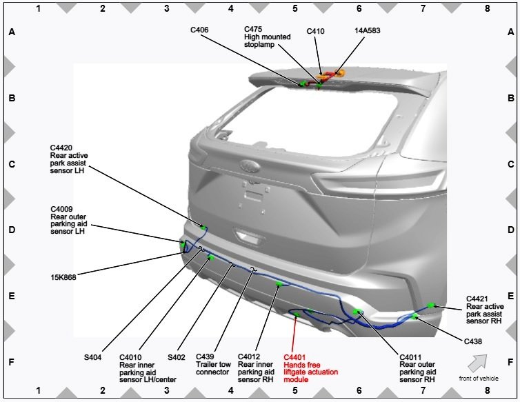
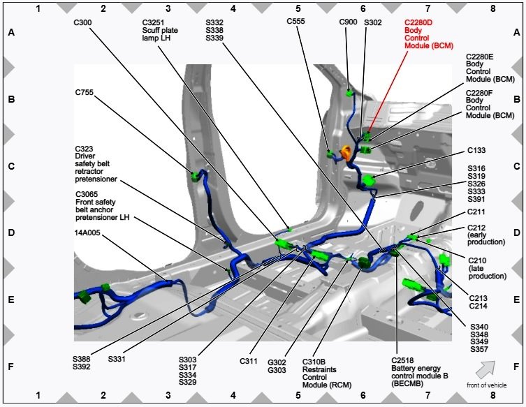
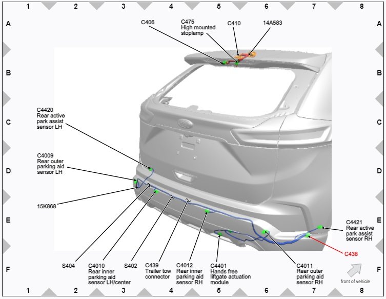
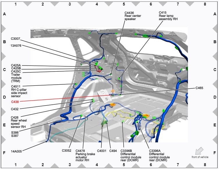
As informational references toward your researching component costs and connector/circuitry availability & requirements, the following are PDF links to related sections from the 2020 Edge Workshop Manual (since you did not mention model year) and connector/component location diagram images. It appears the added Hands Free Liftgate Actuation module with the Upper & Lower sensors deliver an "open sesame" message to the Body Control Module, which then triggers the liftgate to open, similar to using the dash or cargo area switches. Module programming may also be required, perhaps using Forscan, but I am not certain. I am unsure if your local dealership can get authorization to add hands free liftgate actuation, just in case you are not a do-it-yourself owner. It would likely be much more costly to add than the factory-installed option pricing. Good luck! Hands Free Liftgate Actuation Components Description and Location Diagram - 2020 Edge Workshop Manual.pdf Hands-Free Liftgate Actuation Module Removal and Installation - 2020 Edge Workshop Manual.pdf Hands-Free Liftgate Actuation Upper Sensor Removal and Installation - 2020 Edge Workshop Manual.pdf Hands-Free Liftgate Actuation Lower Sensor Removal and Installation - 2020 Edge Workshop Manual.pdf Hands Free Liftgate Wiring Diagram - 2020 Edge Workshop Manual.pdf Connector C4401 Wiring Legend Hands Free Liftgate Actuation Module - 2020 Edge Workshop Manual.pdf Connector C438 Wiring Legend - 2020 Edge Workshop Manual.pdf Connector C2280D Body Control Module Wiring Legend.pdf
-
Body Control Module DTC U0256 Pinpoint P diagnostic routine from 2017 Edge Workshop Manual... Good luck! U0256:87 DTC Fault Trigger Conditions DTC Description Fault Trigger Conditions U0256:87 Lost Communication With Front Controls Interface Module "A" : Missing Message A continuous memory DTC that sets in the BCM if messages from the FCIM through the GWM are missing. Possible Sources Communication network concern Battery voltage concern GWM concern FCIM BCM PINPOINT TEST P: U0256:87 P1 VERIFY THE CUSTOMER CONCERN Ignition ON. Verify there is an observable symptom present. Center Stack Controls Continue To Be Inoperative ? Is an observable symptom present? Yes GO to P2 No The system is operating normally at this time. The DTC may have been set due to high network traffic or an intermittent fault condition. CLEAR the DTC. P2 CHECK THE COMMUNICATION NETWORK Using a diagnostic scan tool, perform a network test. Does the FCIM pass the network test? Yes GO to P3 No DIAGNOSE no communication with the FCIM. REFER to: Communications Network (418-00 Module Communications Network, Diagnosis and Testing). P3 CHECK THE BCM (BODY CONTROL MODULE) CONTINUOUS MEMORY DIAGNOSTIC TROUBLE CODES (CMDTCS) Using a diagnostic scan tool, clear the Diagnostic Trouble Codes (DTCs). Wait 10 seconds. Using a diagnostic scan tool, check the BCM Continuous Memory Diagnostic Trouble Codes (CMDTCs). Is DTC B11D9:16, B11D9:17, U3006:16, U3006:17, U3007:16, U3007:17, U3013:16, U3013:17, U3014:16 or U3014:17 recorded? Yes For DTC B11D9:16, U3006:16, U3007:16, U3013:16 or U3014:16, GO to Pinpoint Test J For DTC B11D9:17, U3006:17, U3007:17, U3013:17 or U3014:17, GO to Pinpoint Test K No GO to P4 P4 RETRIEVE THE DIAGNOSTIC TROUBLE CODES (DTCS) FROM THE FCIM (FRONT CONTROLS INTERFACE MODULE) SELF-TEST Using a diagnostic scan tool, perform the FCIM self-test. Are any Diagnostic Trouble Codes (DTCs) recorded? Yes REFER to: Information and Entertainment System (415-00A Information and Entertainment System - General Information - Vehicles With: AM/FM/CD/SYNC, Diagnosis and Testing). REFER to: Information and Entertainment System (415-00B Information and Entertainment System - General Information - Vehicles With: Touchscreen Display, Diagnosis and Testing). REFER to: Information and Entertainment System (415-00C Information and Entertainment System - General Information - Vehicles With: Sony Audio System, Diagnosis and Testing). No GO to P5 P5 RECHECK THE BCM (BODY CONTROL MODULE) CONTINUOUS MEMORY DIAGNOSTIC TROUBLE CODES (CMDTCS) Using a diagnostic scan tool, clear the Diagnostic Trouble Codes (DTCs). Wait 10 seconds. Using a diagnostic scan tool, check the BCM Continuous Memory Diagnostic Trouble Codes (CMDTCs). Is DTC U0256:87 still present? Yes GO to P6 No The system is operating correctly at this time. The DTC may have been set due to high network traffic or an intermittent fault condition. P6 CHECK FOR DTC (DIAGNOSTIC TROUBLE CODE) U0256 SET IN OTHER MODULES Using a diagnostic scan tool, clear the Diagnostic Trouble Codes (DTCs). Ignition OFF. Ignition ON. Wait 10 seconds. Using a diagnostic scan tool, retrieve all Continuous Memory Diagnostic Trouble Codes (CMDTCs). Is DTC U0256 set in any other module? Yes GO to P7 No GO to P8 P7 CHECK FOR CORRECT FCIM (FRONT CONTROLS INTERFACE MODULE) OPERATION Disconnect and inspect the FCIM connector. Repair: corrosion (install new connector or terminals - clean module pins) damaged or bent pins - install new terminals/pins pushed-out pins - install new pins as necessary Reconnect the FCIM connector. Make sure it seats and latches correctly. Operate the system and determine if the concern is still present. Is the concern still present? Yes CHECK OASIS for any applicable service articles: TSB, GSB, SSM or FSA. If a service article exists for this concern, DISCONTINUE this test and FOLLOW the service article instructions. If no service articles address this concern, VIN required to access Guided Routine (FCIM) No The system is operating correctly at this time. The concern may have been caused by module connections. ADDRESS the root cause of any connector or pin issues. P8 CHECK FOR CORRECT BCM (BODY CONTROL MODULE) OPERATION Disconnect and inspect all BCM connectors. Repair: corrosion (install new connector or terminals - clean module pins) damaged or bent pins - install new terminals/pins pushed-out pins - install new pins as necessary Reconnect the BCM connectors. Make sure they seat and latch correctly. Operate the system and determine if the concern is still present. Is the concern still present? Yes CHECK OASIS for any applicable service articles: TSB, GSB, SSM or FSA. If a service article exists for this concern, DISCONTINUE this test and FOLLOW the service article instructions. If no service articles address this concern, VIN required to access Guided Routine (BCM) No The system is operating correctly at this time. The concern may have been caused by module connections. ADDRESS the root cause of any connector or pin issues.
-
The action of clearing DTCs, and running self-test routines on involved modules afterward, is repeatedly mentioned in the Pinpoint K diagnostic in my prior post, above. It is entirely possible that your Edge's failing/failed battery condition is the root cause of the many DTCs that Forscan revealed. Clearing the DTCs very well may restore the operation of your center-stack controls. Please let us know how it turns out. Good luck!
-
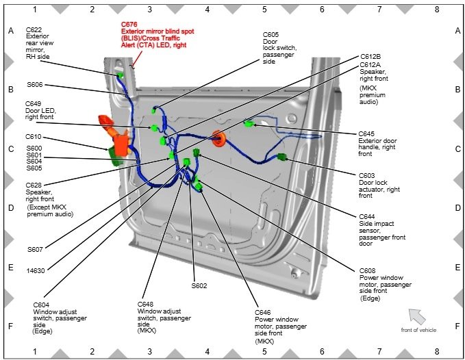
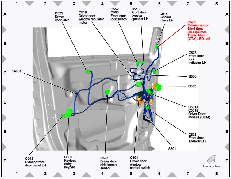
I noticed also that your post also did not mention which side -- right or left -- mirror glass had been pilfered. Below are PDF download links for Outside Mirror removal and installation instructions and right/passenger's door Connector C676 connector wiring legend, and also the location diagram image for right/passenger's door. I compared the connector information for 2014/GEN 1 and for 2015 GEN 2. They are identical, with C576 for left/driver's door and C676 for right/passenger's door. Good luck! Exterior Mirror Removal and Installation - 2015 Edge Workshop Manual.pdf BLIS Mirror Connector C676 Wiring Legend - 2014 Edge Workshop Manual.pdf
-
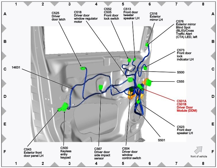
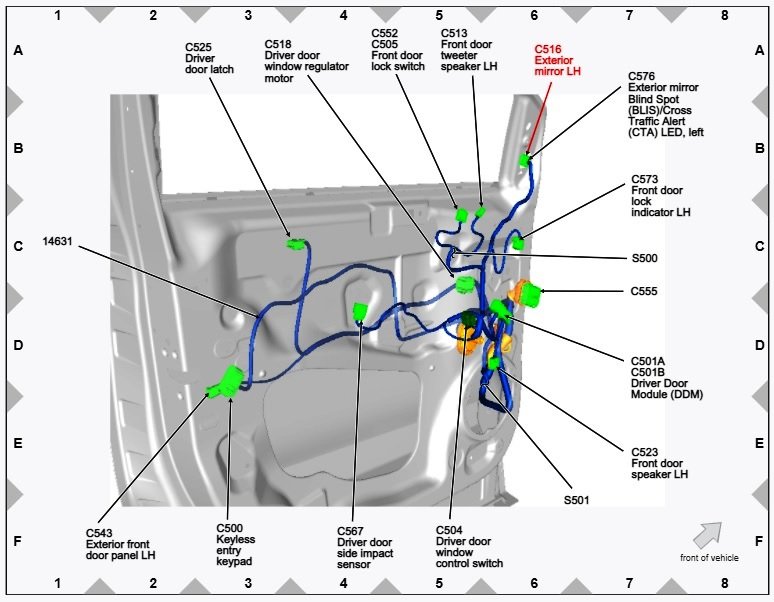
Since you did not mention your Edge's model year, I took a chance and pulled wiring and connector info from the 2015 Edge Workshop Manual, hopeful that your Edge is GEN 2. If not, let us know your Edge's model year and I'll look it up to see if differences exist. Below are PDF download links and reference diagram images. Good luck! Door Module-to-Mirror BLIS Wiring Diagram - 2015 Edge Workshop Manual.pdf Connector C501A Wiring Legend - 2015 Edge Workshop Manual.pdf Connector C501B Wiring Legend - 2015 Edge Workshop Manual.pdf Connector C516 Wiring Legend - 2015 Edge Workshop Manual.pdf BLIS Mirror Connector C576 Wiring Legend - 2015 Edge Workshop Manual.pdf
-
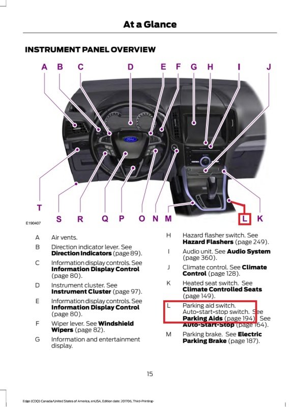
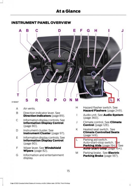
Parking Aid Switch... Good luck!
-
Removing Side Roof Panels?
Haz replied to TonyP's topic in Glass, Lenses, Lighting, Mirrors, Sunroof (BAMR), Wipers
The 2016 Edge Workshop Manual provides the following illustration & description of the Roof Opening Panel Trim components: From Section 501-17 Roof Opening Panel - System Operation and Component Description... Roof Opening Panel Trim (Exterior) There are 2 rear side trim panels, 2 front side trim panels and a front trim panel on the exterior of the roof opening panel assembly. All of the exterior retaining clips are designed to break when removing the trim panels and must be replaced if an original trim panel is to be installed. Always be sure to remove all broken pieces of trim clips from the vehicle when servicing. To service the front side trim panel, both the front trim panel and the rear side trim panel must be removed. When replacing the rectangular retaining clips, the directional arrow cutout on the retainer must match the embossed directional arrow on the trim panel at each retainer location. A new exterior trim panel is serviced with all new retainers in position. New service front trim and rear side trim panels each have one rear spacer block with adhesive tape and a protective film that must be removed during installation. The retainer count needed for each trim panel is as follows: Front trim - 7 square clips. Front side trim - 4 square clips, 3 round clips. Rear side trim - 4 square clips, 2 round clips. Roof Opening Panel Center Beam Trim The roof opening panel center beam trim is an interior trim panel covering the center support beam of the roof opening panel frame While the above description does not mention use of urethane adhesive on factory-installed trim, Section 501-17 provides Removal Instructions for Trim Panel Installed Without Urethane and also Removal instructions for Trim Panels Installed With Urethane. It's worth noting the Workshop Manual states that Trim Panels installed without urethane can be reinstalled using new retention clips and urethane adhesive, but previously serviced Trim Panels reinstalled with urethane adhesive must be discarded and a fully new Trim Panel should be installed with urethane adhesive. And further, that the Rear Side Panel must be removed before the Front Side Panel can be removed. If you are not the Edge's original owner, it's possible that the dealership saw previous service done to Trim Panels in Warranty History, and they know that fully new Trim Panel replacements will be required. Regarding replacement costs, FordParts.com shows MSRP for FT4Z5851916B - Front Sunroof Opening Trim at $364; for FT4Z5851969C - Center Left Sunroof Opening Trim and FT4Z5851968C - Center Right Sunroof Opening Trim around $380 each; and for FT4Z5851969D - Rear Left Sunroof Opening Trim and FT4Z5851968D - Rear Right Sunroof Opening Trim also around $380 each. Below are PDF download links to the Section 501-17 Trim Panel Removal and Installation instructions... Please note that due to PDF formatting issues, action step illustrations may appear on the page following the action step description. It may be worth taking the Workshop Manual removal and installation instructions to the dealership, and ask them if your Edge's trim panels were previously serviced. or, if an engineering change resulted in urethane adhesive being applied at the factory on Edges after a certain Build Date. Good luck! Roof Opening Trim Panel Front Trim - Removal and Installation - 2016 Edge Workshop Manual.pdf Roof Opening Trim Panel Side Trim - Removal and Installation - 2016 Edge Workshop Manual.pdf -
The above photo of the Innova 5410 scan tool shows a U0256 DTC, associated with the Powertrain Control Module's continuous memory, as being the third of three DTCs discovered by the scan tool, though it's unclear if all three DTCs involve the PCM. If the other two Digital Trouble Codes are known, please post them, and we'll work our way through, but for now, let's examine the U0256 PCM DTC. The following is the diagnostic routine prescribed in the 2017 Edge Workshop Manual for determining U0256 DTC cause(s) and corrective action(s), Pinpoint Test K. The total file size of my document attachments are limited here, so I'll post any specific Workshop Manual sections the Pinpoint Test references after your results show a need for the additional information. If you are comfortable providing me your Edge's VIN, feel free to use the Forum's private Message feature, and then any subsequent Guided Diagnostic Routines can be specific for your vehicle, based upon its Build information. Good luck! DTC Fault Trigger Condition-PCM DTC Description Fault Trigger Conditions U0256 Lost Communication With Front Controls Interface Module "A" The PCM sets this DTC if data messages from the Front Control Interface Module (FCIM) through the Gateway Module (GWM) are missing. Normal Operation and Fault Conditions REFER to: Communications Network - System Operation and Component Description (418-00 Module Communications Network, Description and Operation). Possible Sources Communications network concern FCIM BCM (Body Control Module) GWM PCM PINPOINT TEST K: U0256 K1 VERIFY THE CUSTOMER CONCERN Ignition ON. Verify there is an observable symptom present. Is an observable symptom present? Yes GO to K2 The inoperative center stack controls are your observable symptom. No The system is operating normally at this time. The DTC may have been set due to high network traffic or an intermittent fault condition. K2 CHECK THE COMMUNICATION NETWORK Using a diagnostic scan tool, perform a network test. Did the FCIM pass the network test? Yes GO to K3 No REFER to: Communications Network (418-00 Module Communications Network, Diagnosis and Testing). K3 PERFORM FCIM (FRONT CONTROLS INTERFACE MODULE) SELF-TEST Using a diagnostic scan tool, perform a FCIM self-test. Are any Diagnostic Trouble Codes (DTCs) recorded? Yes REFER to: Information and Entertainment System (415-00A Information and Entertainment System - General Information - Vehicles With: AM/FM/CD/SYNC, Diagnosis and Testing). OR REFER to: Information and Entertainment System (415-00B Information and Entertainment System - General Information - Vehicles With: Touchscreen Display, Diagnosis and Testing). OR REFER to: Information and Entertainment System (415-00C Information and Entertainment System - General Information - Vehicles With: Sony Audio System, Diagnosis and Testing). No GO to K4 K4 CHECK THE BCM (BODY CONTROL MODULE) DIAGNOSTIC TROUBLE CODES (DTCS) Using a diagnostic scan tool, retrieve the BCM Diagnostic Trouble Codes (DTCs). Are any Diagnostic Trouble Codes (DTCs) recorded? Yes REFER to: Body Control Module (BCM) (419-10 Multifunction Electronic Modules, Diagnosis and Testing). No GO to K5 K5 PERFORM THE PCM (POWERTRAIN CONTROL MODULE) SELF-TEST Using a diagnostic scan tool, perform the PCM self-test. Is DTC P0562 or DTC P0563 recorded? Yes REFER to PCM DTC Chart in this section. No GO to K6 K6 RECHECK THE PCM (POWERTRAIN CONTROL MODULE) DIAGNOSTIC TROUBLE CODES (DTCS) NOTE: If new modules were installed prior to the DTC being set, the module configuration may be incorrectly set during the PMI, or the PMI may not have been carried out. Using a diagnostic scan tool, clear the Diagnostic Trouble Codes (DTCs). Wait 10 seconds. Repeat the PCM self-test. Is DTC U0256 still present? Yes GO to K7 No The system is operating correctly at this time. The DTC may have been set due to high network traffic or an intermittent fault condition. K7 CHECK FOR DTC (DIAGNOSTIC TROUBLE CODE) U0256 SET IN OTHER MODULES Using a diagnostic scan tool, clear all Diagnostic Trouble Codes (DTCs). Ignition OFF. Ignition ON. Wait 10 seconds. Using a diagnostic scan tool, retrieve all Continuous Memory Diagnostic Trouble Codes (CMDTCs) from all modules. Is DTC U0256:87 set in any other module? Yes GO to K8 No GO to K9 K8 CHECK FOR CORRECT FCIM (FRONT CONTROLS INTERFACE MODULE) OPERATION Ignition OFF. Disconnect and inspect all FCIM connectors. Repair: corrosion (install new connector or terminals – clean module pins) damaged or bent pins – install new terminals/pins pushed-out pins – install new pins as necessary Reconnect all the FCIM connectors. Make sure they seat and latch correctly. Operate the system and determine if the concern is still present. Is the concern still present? Yes CHECK OASIS for any applicable Technical Service Bulletins (TSBs). If a TSB exists for this concern, DISCONTINUE this test and FOLLOW TSB instructions. If no Technical Service Bulletins (TSBs) address this concern, VIN required to access Guided Routine (FCIM) No The system is operating correctly at this time. The concern may have been caused by module connections. ADDRESS the root cause of any connector or pin issues. K9 CHECK FOR CORRECT PCM (POWERTRAIN CONTROL MODULE) OPERATION Ignition OFF. Disconnect and inspect PCM connector. Repair: corrosion (install new connector or terminals – clean module pins) damaged or bent pins – install new terminals/pins pushed-out pins – install new pins as necessary Reconnect the PCM connector. Make sure it seats and latches correctly. Operate the system and determine if the concern is still present. Is the concern still present? Yes CHECK OASIS for any applicable Technical Service Bulletins (TSBs). If a TSB exists for this concern, DISCONTINUE this test and FOLLOW TSB instructions. If no Technical Service Bulletins (TSBs) address this concern, VIN required to access Guided Routine (PCM) No The system is operating correctly at this time. The concern may have been caused by module connections. ADDRESS the root cause of any connector or pin issues.
-
Below is a PDF download link to a section of the 2017 Edge Workshop Manual describing Battery Monitoring System operation, which includes this passage... Battery Replacement If the vehicle battery is replaced, it is very important to perform the BMS Reset using a diagnostic scan tool. If the battery monitoring system reset is not carried out, it holds the old battery parameters and time in service counter in memory. Additionally it tells the system the battery is in an aged state and may limit the Electrical Energy Management system functions. If you don't have a diagnostic scan tool, you may be able to find a national auto parts store willing to scan your Edge's programmable modules for any existing Digital Trouble Codes, which could reveal other contributing factors. Good luck! Charging System - 2.0L EcoBoost - Sys Op and Component Description - 2017 Edge Workshop Manual.pdf Multifunction Electronic Modules Diagnostic and Testing - 2017 Edge Workshop Manual.pdf
-
This past discussion appears to reference this pictured front tower bar, but it's unclear if the full set is offered at this price. Best to contact the seller if it still interests you after reading the discussion. Good luck!
-
Noise from rear during sharp turn
Haz replied to gwhamilton@gmail.com's topic in Brakes, Chassis & Suspension
Our 2012 MKX FWD exhibited a low frequency noise at 20-45 mph, whether traveling straight or turning. I presumed it might be a bearing, but it didn't escalate to metallic sound, so I lived with it for a while. Decided to replace the original Michelin tires at around 85,000 miles, and the noise disappeared entirely. If you have not already, you might try swapping tires front-to-back to see if anything changes. Good luck! -
Aftermarket hitch and drilling
Haz replied to thesavo's topic in Cargo, Hauling, Roof Racks & Towing
I expect your hitch installation has been long-completed, but for the benefit of future discussion readers, below is a PDF download ink to installation instructions for the Ford Accessories hitch. Good luck! Ford Accessories Trailer Hitch Class II Installation Instructions - 2011 to CMY Edge-MKX.pdf -
Windshield washer issue
Haz replied to Colby's topic in Glass, Lenses, Lighting, Mirrors, Sunroof (BAMR), Wipers
Since you know which component is apparently lacking an O-ring, presumably because you see an O-ring present in the other side's non-leaking component, perhaps you can remove that O-ring and seek a dimensional replacement from your local hardware store or auto parts store. Good luck! -
Windshield washer issue
Haz replied to Colby's topic in Glass, Lenses, Lighting, Mirrors, Sunroof (BAMR), Wipers
Underhood illustration of (1) Upper Windshield Washer Hose and (2) Windshield Washer Spray Jet from the 2018 Edge Workshop Manual... Image of Upper Windshield Washer Hose ( FT4Z-17A605-E ) from Ford Parts website... Image of Windshield Washer Spray Nozzle ( FT4Z-17603-C ) from Ford Parts website... Both parts are offered by Ford and by other online sellers, including on eBay, at a variety of prices. Good luck! -
Edge 2007 weather strips
Haz replied to Dude's topic in Glass, Lenses, Lighting, Mirrors, Sunroof (BAMR), Wipers
Glass, Frames and Mechanisms — Exploded View, Rear Door illustration from 2009 Edge Workshop Manual... Item 3 - Weatherstrip Assembly, Rear Door Outer Link to Left Hand/Driver's Side - Black Finish Link to Right Hand/Passenger Side - Black Finish Link to Left Hand/Driver's Side - Bright Finish Link to Right Hand/Passenger Side - Bright Finish Note: Bright Finish shows discontinued at linked site and several other online sellers. None showing for sale on eBay. If needed, ask Local Ford Dealer to search Dealer Parts System for availability, otherwise check used parts yards. Item 4 - Weatherstrip, Door Belt, Rear Door Inner Link to Left Hand/Driver's Side Inner Link to Right Hand/Passenger Side Inner Note: Right Hand/Passenger Side shows discontinued at linked site and several other online sellers. Searching part number shows several new examples for sale on eBay. Otherwise, ask Local Ford Dealer to search Dealer Parts System for availability, or check used parts yards. And finally, linked sites are used for part number reference and illustration of compatibility of fitment and retail availability only. I have not purchased items from these sellers and I don't know how their pricing and/or customer service compare to other sellers, including your Local Ford Dealer. Good luck! -
Edge 2007 weather strips
Haz replied to Dude's topic in Glass, Lenses, Lighting, Mirrors, Sunroof (BAMR), Wipers
Glass, Frames and Mechanisms — Exploded View, Front Door illustration from 2009 Edge Workshop Manual... Item 3 - Weatherstrip Assembly, Front Door Outer Link to Left Hand/Driver's Side - Black Finish Link to Right Hand/Passenger Side - Black Finish Link to Left Hand/Driver's Side - Bright Finish Link to Right Hand/Passenger Side - Bright Finish Item 4 - Weatherstrip, Door Belt, Front Door Inner Link to Left Hand/Driver's Side Inner Link to Right Hand/Passenger Side Inner Good luck! -
Below are PDF download links to relevant sections of the 2009 Edge Workshop Manual... Seating Description and Operation - 2009 Edge-MKX Workshop Manual.pdf Front Seat Exploded View - Removal and Installation - 2009 Edge-MKX Workshop Manual.pdf Front Seat Cushion - Removal and Installation - 2009 Edge-MKX Workshop Manual.pdf Front Seat Backrest - Removal & Installation - 2009 Edge-MKX Workshop Manual.pdf Front Seat Backrest Cover, Without Fold Flat - Removal & Installation - 2009 Edge-MKX Workshop Manual.pdf Front Seat Cushion Cover - Removal and Installation - 2009 Edge-MKX Workshop Manual.pdf Front Seat Track - Removal and Installation - 2009 Edge-MKX Workshop Manual.pdf Seating Torque Specifications - 2009 Edge-MKX Workshop Manual.pdf Link to rudimentary driver's seat removal & installation video. Link to MACT Ford Edge 2011 passenger seat removal and installation video. Driver's seat heating element connector C3283 location... Driver's seat heating element C3283 connector image... Driver's seat heating element C3283 connector pin/circuit legend... Heated Seats wiring diagram with Driver's seat heating element highlighted (red oval) from 2009 Edge-MKX Workshop Manual... Good luck!
-
I’ve Always Said No To Sunroofs...
Haz replied to chipdog4's topic in Cargo, Hauling, Roof Racks & Towing
Below are PDF download links to relevant sections of the 2019 Edge Workshop Manual. Good luck! Airbag and Seatbelt Pretensioner Supplemental Restraint System (SRS) - Component Location - 2019 Edge Workshop Manual.pdf Supplemental Restraint System (SRS) Depowering - 2019 Edge Workshop Manual.pdf Supplemental Restraint System (SRS) Repowering - 2019 Edge Workshop Manual.pdf -
I’ve Always Said No To Sunroofs...
Haz replied to chipdog4's topic in Cargo, Hauling, Roof Racks & Towing
I have access to a secure website used by Ford & Lincoln dealership service technicians. Not sure how fully useful this 2015 MACT Ford Edge Garage reference set can be toward your 2020 ST. Good luck! -
I’ve Always Said No To Sunroofs...
Haz replied to chipdog4's topic in Cargo, Hauling, Roof Racks & Towing
Below are PDF download links to relevant sections of the 2019 Edge Workshop Manual. Please note that related illustrations appear immediately following the numbered action-steps, but occasionally are on the next page in the PDF, due to formatting. You have certainly owned many nice FOMOCO vehicles. Good luck! Roof Rail Removal and Installation - 2019 Edge Workshop Manual.pdf Headliner Lowering - 2019 Edge Workshop Manual.pdf A-Pillar Trim Panel Removal and Installation - 2019 Edge Workshop Manual.pdf B-Pillar Trim Panel Removal and Installation - 2019 Edge Workshop Manual.pdf C-Pillar Trim Panel Removal and Installation - 2019 Edge Workshop Manual.pdf Loadspace Trim Panel Removal and Installation - 2019 Edge Workshop Manual.pdf -
Back during the Oil Crisis's of 1973 and 1979 , when fuel prices spiked and gas station line-ups & criminal fuel siphoning were prevalent, many of us Boomers added lock cylinders to the fuel doors of our vehicles. Using a hole saw to drill the fuel door was a little daunting, because of its permanence, but the added cam-locking arm provided peace-of-mind and prevented fuel theft. Judging from your photos, a shorter depth weather-resistant lock cylinder may work for you, though it might require eliminating the latch-unlatch post that your Edge's fuel door appears to include. These are available online, or you may find a suitable solution at your local hardware store and/or nationwide big-box home supply center, if you would choose to undertake this sort of project... Below are PDF links to dimensional drawings of the above-referenced lock cylinders. Good luck! 13105A71_Weather-Resistant Cam Lock.PDF 13105A72_Weather-Resistant Cam Lock.PDF
-
First, I regret that I did not look at the compatibility of the specific part number to your 2015 Edge Titanium, which the review website, when configured for 2015 Edge, says is not compatible. Ford's online Accessories catalog shows the 8U5Z-9C268-B Locking Fuel Plug as fitting only 2010-2014 Edge... FITS THESE VEHICLES Ford Edge 2010-2014 Ford Escape Hybrid 2010-2012 Ford Escape 2009-2012 Ford Expedition 2010-2017 Ford Explorer 2008-2019 Ford F-150 2009-2014 Ford Fiesta 2011-2019 Ford Flex 2009-2019 Ford Focus 2012-2018 Ford Fusion 2010-2012 Ford Mustang 2010-2014 Ford Taurus 2010-2019 Lincoln MKS 2009-2016 Lincoln MKT 2010-2018 Lincoln MKX 2011-2014 Lincoln MKZ 2010-2011 Lincoln Navigator 2010-2017 Similarly, Ford's online Parts catalog configured for 2015 Edge indicates the 8U5Z-9C268-B Locking Fuel Plug... This part does not match your vehicle. Because you personally entered the order online, and the packaging states "This package cannot be returned if opened", I don't expect you could obtain a refund. Once again, I regret not having previously done this research. Good luck!