Haz
-
Posts
1,568 -
Joined
-
Last visited
-
Days Won
439
Content Type
Profiles
Forums
Gallery
Everything posted by Haz
-
TECHNICAL SERVICE BULLETIN 2021 Edge/Nautilus - Various SYNC4 Concerns 22-2062 25 February 2022 Model: Ford 2021 Edge Lincoln 2021 Nautilus Issue: Some 2021 Edge/Nautilus vehicles may experience one or more of the following symptoms: Android Auto connection concerns, Apple CarPlay connection concerns, Information and entertainment screen freezing/locking up, windows media audio (WMA) files not playing properly from a universal serial bus (USB) device, intermittent blank information and entertainment screen, Bluetooth connectivity concerns, incorrect Owner's Manual language for French, frozen or delayed response for touch screen improvements. This may be due to the software in the accessory protocol interface module (APIM). To correct the condition, follow the Service Procedure to reprogram the APIM. NOTE: The APIM software update that addresses the symptom listed in this bulletin may have been sent via Ford Power-Up software updates delivered over-the-air (OTA) to connected vehicles that have automatic updates enabled through the SYNC 4 screen. Enter the vehicle identification number (VIN) in Professional Technician System (PTS) and check the OTA Dashboard under the Connected Vehicle tab for OTA update history. If an update to the APIM has successfully completed recently and the customer is reporting the symptoms are no longer present, this article may not apply. Action: Follow the Service Procedure steps to correct the condition on vehicles that meet all of the following criteria: • 2021 Edge/Nautilus • At least one of the following: - Android Auto connection concerns - Apple CarPlay connection concerns - Information and entertainment screen freezing/locking up - WMA files not playing properly from a USB device - Intermittent blank information and entertainment screen - Bluetooth connectivity concerns - Incorrect Owner’s Manual language for French - Frozen or delayed response for touch screen improvements Warranty Status: Eligible under provisions of New Vehicle Limited Warranty (NVLW)/Service Part Warranty (SPW)/Special Service Part (SSP)/Extended Service Plan (ESP) coverage. Limits/policies/prior approvals are not altered by a TSB. NVLW/SPW/SSP/ESP coverage limits are determined by the identified causal part and verified using the OASIS part coverage tool. Labor Times Description Operation No. Time 2021 Edge/Nautilus Check Software Reprogram APIM (Do Not Use With Any Other Labor Operations) 222062A 1.5 Hrs. 2021 Edge/Nautilus Check Software Reprogram GWM and APIM (Do Not Use With Any Other Labor Operations) 222062B 1.8 Hrs. Repair/Claim Coding Causal Part: 14G670 Condition Code: 04 Service Procedure NOTE: Ask the customer to bring their spare key fob to assist in the Ford Diagnosis and Repair System (FDRS) programming. NOTE: The gateway module (GWM) must be at the latest software level before the APIM update can be performed. Updated APIM software will not show as being available in FDRS until the GWM has been successfully updated. 1. Connect the vehicle communications module (VCM) II, vehicle communication and measurement module (VCMM) or later level to the vehicle data link connector (DLC) and the diagnostic scan tool USB port. Start a vehicle session with the FDRS and select the toolbox tab to see the available software updates. 2. Is a GWM software update available? (1). Yes - proceed to Step 3. (2). No - proceed to Step 4. 3. Update the GWM using the latest version of FDRS. Refer to Workshop Manual (WSM), Section 418-01A for Module Reprogramming. (1). Connect a battery charger to the 12 volt battery. NOTE: A blank 32GB or larger USB flash drive is required for GWM update. Make sure the USB flash drive being used is formatted correctly. To see the available drives, hold down the Windows icon keyboard key and press the E keyboard key. Right click on the USB flash drive and select Properties. If File System under the General tab is not exFAT, the drive must be formatted. To format the USB flash drive, right click on the USB flash drive, select Format, select exFAT for the File System, and select Default Allocation Size for the Allocation Unit Size. De-selecting Quick Format is not necessary and will result in a lengthier operation. (2). Using the FDRS, reprogram the GWM by selecting GWM - Gateway Module A (GWM) Software Update. Follow all on-screen instructions carefully. (3). When prompted, connect the USB flash drive to the FDRS diagnostic scan tool. NOTE: It may take up to 30 seconds for the vehicle to recognize the USB flash drive. (4). When prompted by the FDRS, safely remove/eject the USB flash drive from the FDRS diagnostic scan tool. Close all of the vehicle's doors and plug in the USB flash drive into the USB media hub in the vehicle. The vehicle will recognize the USB flash drive and allow up to 10 minutes for the update to start automatically. (5). Next the SYNC touchscreen will prompt to restart the vehicle. With the USB flash drive still in the vehicle, turn the vehicle ignition OFF and keep all of the vehicle's doors closed and allow the vehicle to power down for at least 5 minutes. The SYNC touchscreen may stay turned on for a few more seconds after turning off the vehicle. (6). With the USB flash drive still in the vehicle and after waiting 5 minutes with all of the vehicle's doors closed, turn the vehicle ignition ON. Allow the vehicle to power on and look for a Update Successful pop up in the vehicle SYNC touchscreen. If a Restart Is Required message pops up again, this may be due to having the vehicle's doors open when turning off the ignition. (7). Once the pop-up stating Update Successful appears in the SYNC screen, select Close, remove the USB flash drive from the USB media hub and connect it to the FDRS diagnostic scan tool, and select OK on the FDRS. This initiates the remaining automated configuration steps and reports the GWM assembly, vehicle interface processor (VIP), calibration, customer interface processor (CIP), and application software levels to the Ford online database. Failure to follow this step results in an inaccurate database as well as omitted, improperly installed, or improperly configured applications (features) such as navigation (if equipped). It is normal for the GWM to reset during this step. 4. If a GWM software update was performed, re-run the network test on the FDRS. Is an APIM software update available? (1). Yes - proceed to Step 5. (2). No - this article does not apply. Refer to WSM, Section 415-00. NOTE: A blank 64GB or larger USB flash drive is required for APIM software update. Make sure the USB flash drive being used is formatted correctly. To see the available drives, hold down the Windows icon keyboard key and press the E keyboard key. Right click on the USB flash drive and select Properties. If File System under the General tab is not exFAT, the drive must be formatted. To format the USB flash drive, right click on the USB flash drive, select Format, select exFAT for the File System, and select Default Allocation Size for the Allocation Unit Size. Make sure the Quick Format box is selected. If it is not selected, it will result in a lengthier operation. 5. Verify a battery charger connected to the vehicle's 12 volt battery. Set the charger to maintain 12.6-13.6 volts. 6. Close all doors on the vehicle. Locking the latch mechanically while the door is open will simulate a closed door. 7. Download and run the APIM Software Update application on the FDRS and follow the on-screen prompts. If any error conditions are experienced during programming, refer to WSM Section 418-01A > General Procedures > Module Programming for the Error Condition Table. NOTE: Downloading software to the FDRS may take up to 1 hour and saving that data to the USB flash drive may take up to 30 minutes. During this time, no interaction is needed with the FDRS. (1). Follow the FDRS prompts and install the USB flash drive into the vehicle. Wait 5 minutes for the updating prompts to show up in the sync screen. NOTE: It may take up to 5 minutes for the vehicle to recognize the USB flash drive. All doors must remain closed until the SYNC screen prompts a restart is required. To view the progress, you can drop down the updating screen in the sync screen. It make take up to 20 minutes for the vehicle to download all of the data from the USB flash drive. (2). When the USB has downloaded to the vehicle, the touchscreen indicates a message for Restart Required. The ignition needs to be turned off for 10 minutes. Keep all vehicle doors closed during this key off time. (3). After the 10 minutes and with all of the vehicle's doors closed, start the vehicle and allow another 5 minutes for the Update Successful message to appear in SYNC screen. Once the Update Successful message appears, the USB flash drive may be removed, and the doors opened. A popup indicating the software has already been installed in the vehicle may show up in the SYNC screen instead of the Update Successful message. This message should be treated as a response that the APIM software has been updated. (4). Return the USB thumb drive to the FDRS and follow the on-screen prompts to complete the procedure. PDF download link to the document... TSB 22-2062 - 2021 Edge-Nautilus - Various Sync Concerns - February 25, 2022.pdf
-
Sync 4A disasters, am I the only one?
Haz replied to Xfire's topic in Audio, Backup, Navigation & SYNC
In late February, Ford issued a Technical Service Bulletin exclusively for 2021 Edge/Nautilus to address a laundry list of Sync 4 problems that surfaced in vehicles lacking an over-the-air APIM/Sync Module update. Determining if the TSB applies is accomplished by looking up the vehicle's OTA Update Dashboard for the most recent APIM/Sync Module update timing. You might try contacting your dealer and have them pull up your Edge's APIM/Sync Module update history & OASIS Sync Service histories, to see if this TSB service action might solve your Edge's Sync troubles. If the TSB applies, the repair requires a visit to the dealership with the vehicle and both keyfobs. Below is a PDF download link to the document... TSB 22-2062 2021 Edge-Nautilus Various Sync Concerns - February 25, 2022.pdf Good luck! -
I've been working with Hawie offline. We determined that his Edge's liftgate glass had been previously broken and, unfortunately, was replaced with a unit lacking the in-glass antenna grid(s). He researched adding an aftermarket stick-on antenna grid to the inside of the replacement glass, but subsequently found online feedback saying rear window defroster usage would create radio interference. He experimented using a simple length of wire inside the window aperture and his Edge did gain some local station reception. At last report, he was pursuing an exterior-mount aftermarket antenna as a long-term solution, which he might eventually provide us an update on. Good luck!
-
need more power on the wireless charging pad
Haz replied to ben senise's topic in Audio, Backup, Navigation & SYNC
From the 2020 Edge Workshop Manual... Wireless Accessory Charging Module (WACM) - Overview The WACM is a 5 Watt wireless power transmitter designed to energize a secondary coil that may already be equipped in a secondary device (smart phone), or as an added accessory (wireless charging phone sleeve). The WACM supports wireless charging of the Wireless Power Consortium’s (WPC) Qi, pronounced “Chee". The WACM is a powered at all time node from fused battery and performs network management on HS-CAN3 . Wireless charging status is provided as a CAN signal on the HS-CAN3 . The BCM provides a protected switch to battery input to the WACM when an interior passive key search is in progress to disable the wireless charging feature. This is to prevent possible interference with the passive key when placed in close proximity to the WACM during a charge session of a secondary device. A redundant CAN signal is also sent by the BCM in addition to the protected switch to battery input. Good luck! -
Images from the 2021 Edge Workshop Manual... Good luck!
-
Park outdoors: Ford expands recall for possible engine fires
Haz replied to 1004ron's topic in Articles, News & Reviews
I appreciate you quoting from the photo caption, which is unrelated to underhood fire risk and lacks any need to park involved vehicles outside, because that Safety Recall 22S43 has been previously detailed in the Forum, and affected Edge owners will benefit from your reminder... The 'Possible Engine Fires' headline and underhood fire topic of the article relates to Safety Recalls 22S36 & 22S48, which apply to 2021 Expedition and Navigator, as well as Safety Recall 22S47 which applies to 2021/2022 Corsair and 2022 Maverick. Good luck! -
Aftermarket hitch and drilling
Haz replied to thesavo's topic in Cargo, Hauling, Roof Racks & Towing
Per the instructions linked below, the fasteners removed from the bumper bar may be retained and reused for the hitch installation... 2015-2018 Edge Factory No-Drill Trailer Hitch Installation Instructions 2.pdf Good luck! -
Park outdoors: Ford expands recall for possible engine fires
Haz replied to 1004ron's topic in Articles, News & Reviews
It is worth noting that Edge, MKX, and Nautilus are not involved in the described headlined Recalls. Good luck! -
From the 2015 Edge Workshop Manual, as PDF download links below... Tire Pressure Monitoring System (TPMS) - System Operation and Component Description - 2015 Edge Workshop Manual.pdf Tire Pressure Monitoring System (TPMS) - Diagnosis and Testing - 2015 Edge Workshop Manual.pdf Tire Pressure Monitoring System (TPMS) - Component Location - 2015 Edge Workshop Manual.pdf The Workshop Manual does not provide diagnostic procedures specific to the Radio Transceiver Module (RTM), but does offer evaluation of the RTM in the context of the involved component -- in this case, within the TPMS diagnostics linked above. If your diagnostic efforts progress to requiring electrical connector details, just let me know and I will provide them. If your efforts progress to the RTM... Radio Transceiver Module (RTM) - Removal and Installation - 2015 Edge Workshop Manual.pdf Headliner Lowering - 2015 Edge Workshop Manual.pdf Good luck!
-
Below is a PDF download link to a job aid on parasitic current draw analysis... Parasitic Battery Drain Job Aid.pdf Good luck!
-
'Notice To Dealers' letter updated; Owner Refunds information added, Sample Letter to Owners added, and Recall Repair Technical Info added. Good luck!
-
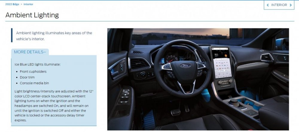
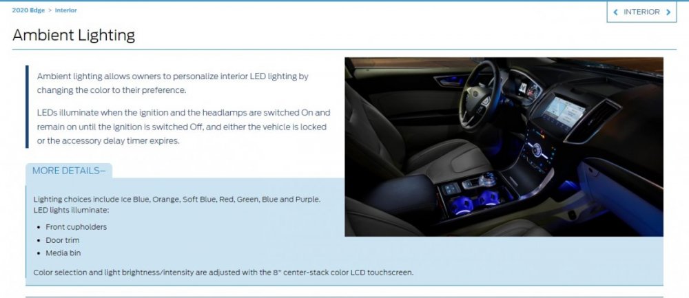
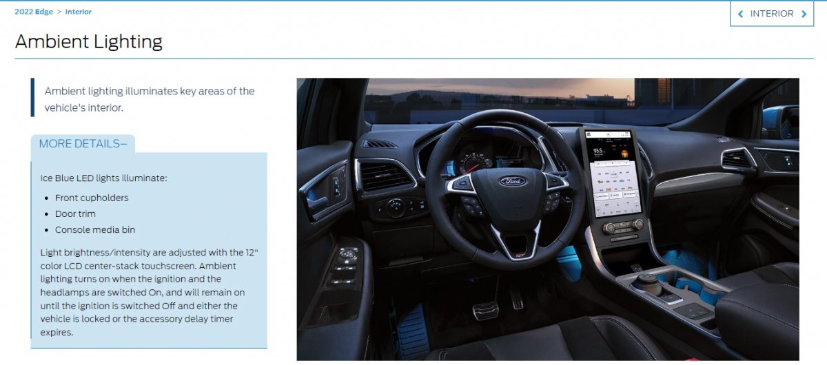
An online resource for dealership sales reps indicates Ice Blue as the only Ambient Light color on 2022 & 2021 Edges... ...and it shows 2020 Edge being the last model year having multi-color Ambient Light selection... According to Helm Inc, Ford has not yet released to them the 2022 Edge Workshop Manual. Hopefully, they are correcting issues like the Ambient Light feature in the 2022 Edge edition, which Helm will eventually market on a CD. Omar302's encouragement to report the unreliable 'On' Ambient Lights setting to your dealership Service department is worthwhile. If they feed the issue's existence back up the chain, through the Technical Assistance Center, a corrective software update could be developed. As an example -- and for any GEN 1+ Edge/MKX owners coming to this discussion with a comparable issue -- below is a PDF download link to TSB 14-0175... TSB 14-0175 - 2011-2014 Edge & MKX - Ambient Lighting Defaults to White or Ice Blue After Cycling Ignition Switch.pdf Good luck!
-
From the 2022 Edge Workshop Manual... Ambient Lighting The ambient lighting subsystem consists of the BCM , and the Light Emitting Diodes (LEDs) located within the floor console, front and rear door panels, instrument panel and front and rear footwell areas. The ambient lighting is operational when the ignition is in any state other than OFF (the exception is when it is used in conjunction with the illuminated entry/exit features), the headlamps are on and the outside ambient light level is low. The BCM provides the voltage to the ambient lighting system, while the touchscreen ( FDIM ) is used to cycle through the different color variations or turn the ambient lighting feature on or off. A LIN circuit is routed from the BCM to all of the Light Emitting Diodes (LEDs). There are 3 Light Emitting Diodes (LEDs) (red, blue and green) housed within each LED assembly. By illuminating various color combinations, the Light Emitting Diodes (LEDs) are able to produce different colors of ambient light. The APIM uses software to monitor the user interface from the touchscreen. Based on the ambient lighting system selections made using the touchscreen, the APIM sends ambient light color request and ambient light intensity request messages over the communication network for color and brightness settings. The BCM retains the last color and brightness setting between uses. I looked for Ambient Lighting TSBs and SSMs, but there are none. Perhaps the next OTA update will correct it. Good luck!
-
Good thought, enigma-2... Good luck!
-
On your 2019 Edge, the roof-mounted sharkfin antenna only provides signals for the GPS and satellite radio functions. Per the 2019 Edge Workshop Manual, with additional relevant sections in PDF download links and images below... GPS /Satellite Radio Antenna The GPS /satellite radio antenna contains a GPS antenna circuit board that receives radio waves containing GPS and satellite radio data (vehicles equipped with a satellite radio). The data is sent through the coaxial cable to the APIM ( GPS data) and through a splitter to the ACM (satellite radio data). Audio Unit Antenna The audio unit antenna (also called the AM / FM 1 antenna) is an on-glass antenna, mounted to the left side of the rear window. It receives AM / FM radio waves and sends them through the audio unit antenna amplifier to the ACM via the audio unit antenna coaxial cable (also called the AM / FM 1 antenna coaxial cable). Audio Unit Antenna Amplifier The audio unit antenna amplifier (also called the AM / FM 1 antenna amplifier) amplifies AM / FM radio signals to improve reception. The amplified signal is sent through a coaxial cable to the ACM . The amplifier is powered by the ACM through the coaxial cable. FM 2 Diversity Antenna The FM 2 diversity antenna is an on-glass antenna, mounted to the right side of the rear window. The FM 2 diversity antenna improves FM reception in urban areas or anywhere large objects reflect FM signals and create multiple FM signal paths. FM 2 Diversity Antenna Amplifier The FM 2 diversity antenna amplifier amplifies FM radio signals and transmits them through a coaxial cable to the ACM . Voltage for the amplifier is provided by the ACM through the coaxial cable. Antenna Inputs Wiring Diagram Pinpoint Test A - Poor AM-FM Reception - Diagnosis and Testing - 2019 Edge Workshop Manual.pdf ACM Antenna Inputs & Amplifier Wiring Diagram - 2019 Edge Workshop Manual.pdf Antenna Isolator Module - Removal and Replacement - 2019 Edge Workshop Manual.pdf AM-FM1 Antenna Amplifier - Removal and Replacement - 2019 Edge Workshop Manual.pdf FM2 Diversity Antenna Amplifier - Removal and Replacement - 2019 Edge Workshop Manual.pdf Audio Unit Antenna Cable Removal and Replacement - 2019 Edge Workshop Manual.pdf Information and Entertainment System - System Operation and Component Description - 2019 Edge Workshop Manual.pdf Audio Front Control Module (ACM) Coaxial Connector C240D AM-FM1 Antenna -2019 Edge Workshop Manual.pdf If you require additional Connector information, please let me know, otherwise... Good luck!
AntennaInputsWiringDiagram-2019EdgeWorkshopManual.thumb.jpg.f4146929884711773f7d35734ddd49a2.jpg)
CoaxialConnectorC240DLocationIllustration-2019EdgeWorkshopManual.jpg.6191f77607d15d28b06821e30d1a90c6.jpg)
-
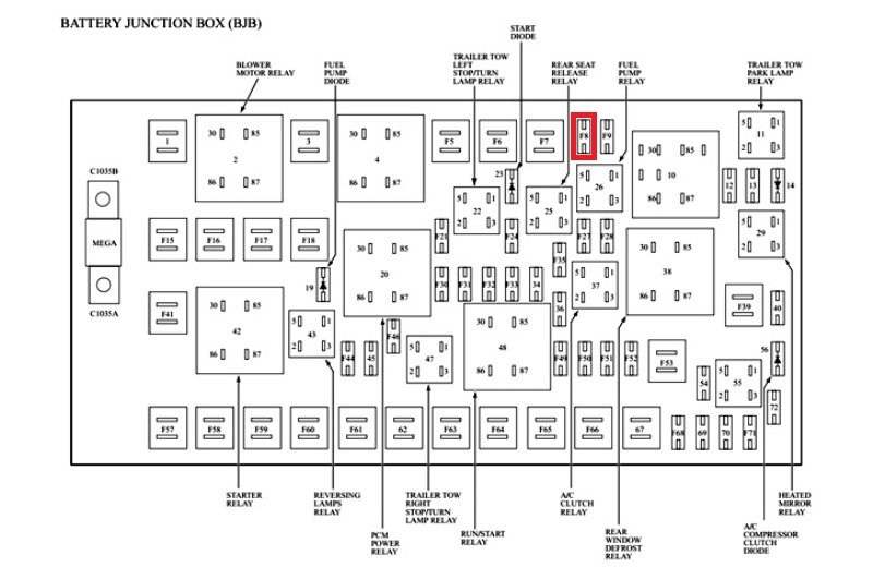
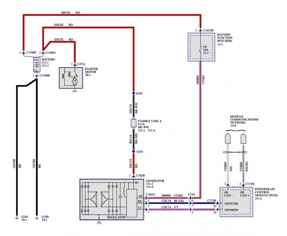
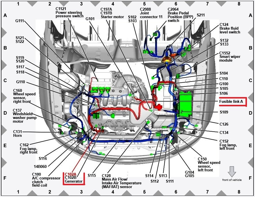
Have you checked fuse F8 in the Battery Junction Box?... Below as PDF download links to relevant sections from the 2008 Edge Workshop Manual Charging System — General Information and Diagnostics - 2008 Edge Workshop Manual.pdf Charging System — Inspection And Verification - 2008 Edge Workshop Manual.pdf Charging System — Diagnostic Trouble Code Chart - 2008 Edge Workshop Manual.pdf Charging System — Diagnostic Pinpoint Test - 2008 Edge Workshop Manual.pdf Charging System Wiring Diagram - 2008 Edge Workshop Manual.pdf Generator Connector C102A Details - 2008 Edge Workshop Manual.pdf Generator Connector C102B Details - 2008 Edge Workshop Manual.pdf Battery Junction Box - Fuse & Relay Locations - 2008 Edge Workshop Manual.pdf Good luck!
-
Aftermarket hitch and drilling
Haz replied to thesavo's topic in Cargo, Hauling, Roof Racks & Towing
Regarding our 2015 MKX, I was fortunate that a prior owner had the factory hitch and Ford Accessories trailer wiring kit installed by the dealer, but it's worth noting that the wiring kit did not enable the trailer tow adjustments to AdvanceTrac and the Distance-To-Empty fuel mileage function. I added the Trailer Sway menu item to the Driver Assist gauge cluster dialogue using Forscan, however it doesn't accept a checkmark to enable functionality. The dealer who installed the cooling system upgrade theorized the Trailer Module would likely be necessary to gain the AdvanceTrac & DTE functions. For my purposes, the gain wasn't worth the additional cost and effort, though the above-linked discussion demonstrates that enthusiastic owner installation of the Trailer Module and required harness is possible. For a more accurate towing DTE calculation, I just reset one of the Trip memories at the beginning of my towing travel and it eventually calculates a useful DTE calculation. Looking at the installation instructions for the Ford wiring kit, which are lengthy, I would be inclined to go with a custom aftermarket semi-plug-and-play harness, just for their simplicity of installation. Good luck! -
Mike: Was the source of the $1,000 repair estimate the Service Department at the dealership where you purchased the Edge new? If so, I expect you voiced comparable displeasure to them about paying for the repair. Did they offer to elevate your case to an Area Factory Service Rep, to see if they could receive a Goodwill authorization from Ford, whereby Ford might cover the cost of the replacement Compressor, if you were willing to pay a percentage, or in-full, for the dealership Labor to install the new Compressor? Did any conversation like that occur, especially if you've bought many of your vehicles there? The terminology would be that you are seeking a Goodwill repair arrangement to ensure your continued customer satisfaction as a long-time Ford & Lincoln owner. Good luck!
-
Hat-tip to WWWPerfA_N0W for standing in the informational gap! PDF download links to 'Pinpoint JD' and its other linked-to references... JD - Crankshaft Position (CKP) Sensor - 2010 FoMoCo Gasoline Powertrain Control Emissions Diagnosis (PC-ED) Manual.pdf Resetting The Keep Alive Memory (KAM) - 2010 FoMoCo Gasoline Powertrain Control Emissions Diagnosis (PC-ED) Manual.pdf Clear the Continuous Diagnostic Trouble Codes (DTCs) and Reset the Emission Monitors Information in the Powertrain Control Module (PCM) - 2010 FoMoCo Gasoline Powertrain Control Emissions Diagnosis (PC-ED) Manual.pdf On Board Diagnostic (OBD) Drive Cycle - 2010 FoMoCo Gasoline Powertrain Control Emissions Diagnosis (PC-ED) Manual.pdf Flash Electrically Erasable Programmable Read Only Memory (EEPROM) - 2010 FoMoCo Gasoline Powertrain Control Emissions Diagnosis (PC-ED) Manual.pdf Good luck!
-
The following is PDF download link for 'No Start Pinpoint Test' from 2010 Gasoline PC/ED Manual... Pinpoint Test For Cranks But Doesn't Start - Fuel or Ignition Issue - 2010 FoMoCo Gasoline Powertrain Control Emissions Diagnosis (PC-ED) Manual.pdf Good luck!
-
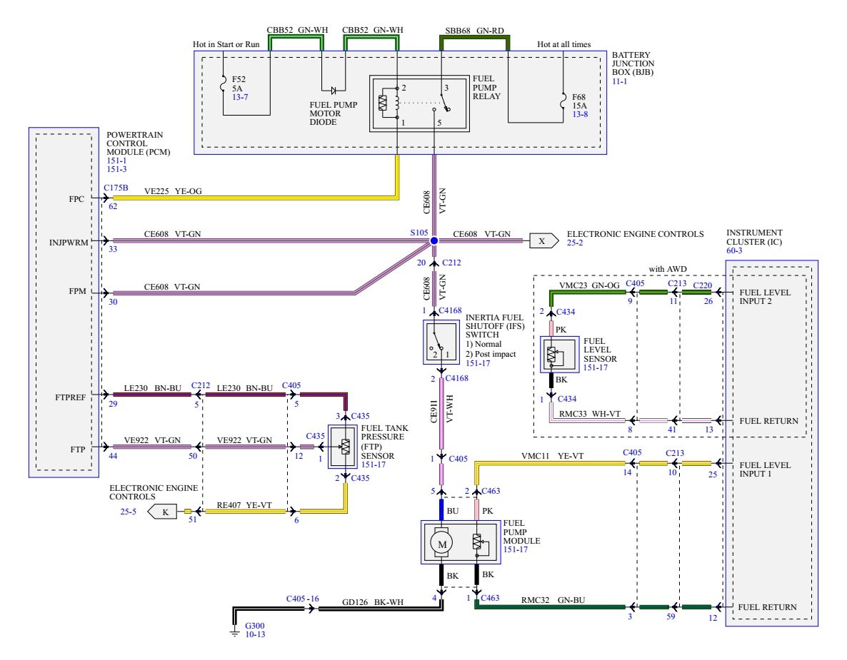
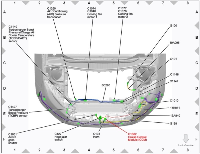
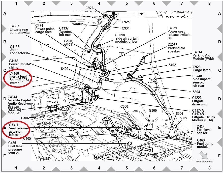
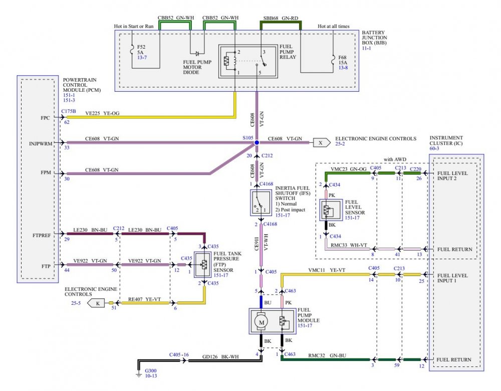
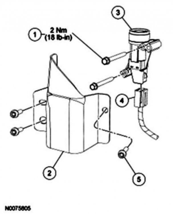
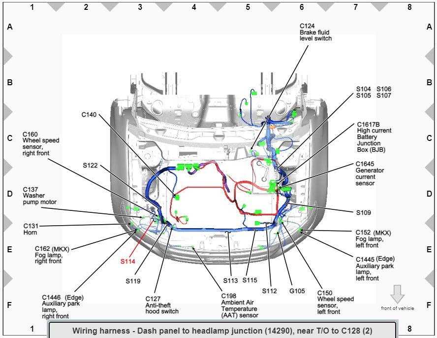
I'm uncertain on interrupted / uninterrupted state of an immovable IFS reset switch. Here is wiring diagram and the IFS switch connector detail. If you've not ruled out IFS involvement, is it possible to verify switch-state by checking across switch's pins 1 & 2, and/or jumper 1 to 2 on harness connector if the switch is determined to be in the interrupted state?
SwitchConnectorC4168Details-2010EdgeWorkshopManual.jpg.67b4a9022c134e4efd5cb738b8fd5fd7.jpg)
-
From the 2010 Edge Workshop Manual.... Fuel System Shutoff Feature The FP module is controlled by the PCM. Electrical power to the FP module is provided through the IFS switch that will de-energize the fuel delivery secondary circuit in the event of a moderate to severe collision. The IFS switch is a safety device, located under the LR quarter trim panel. Should the vehicle shut off after a collision due to this feature, restart the vehicle by first turning the ignition OFF, push the reset button on the IFS switch, then turn the ignition to the ON position. Good luck!
-
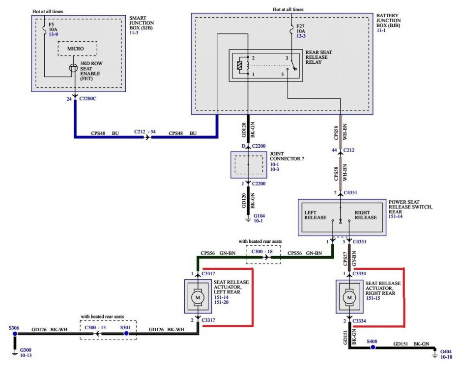
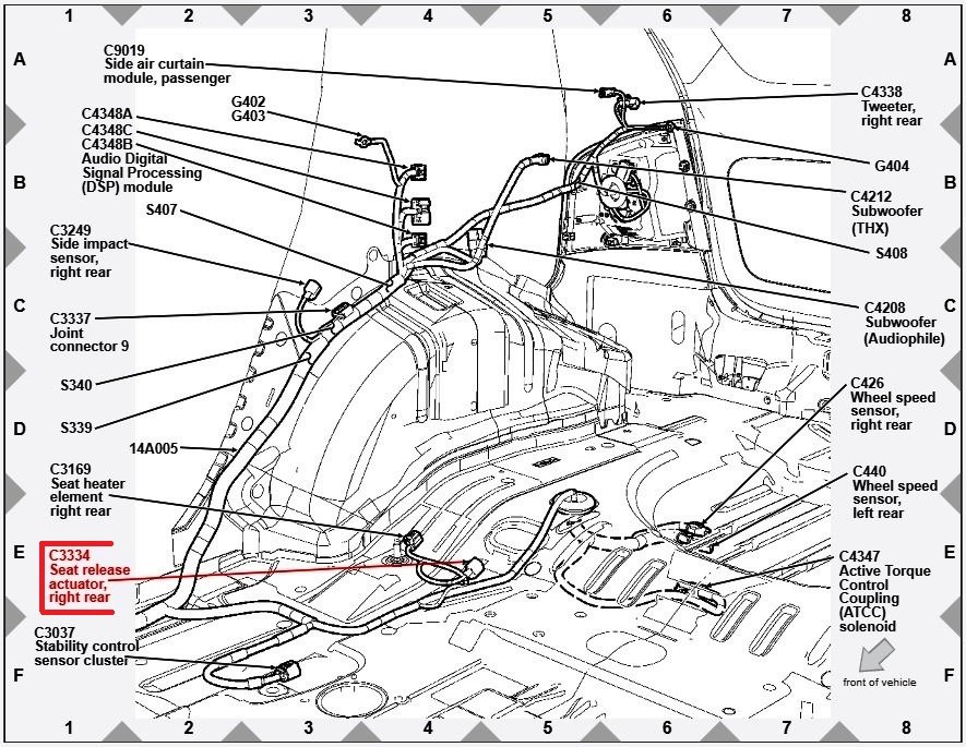
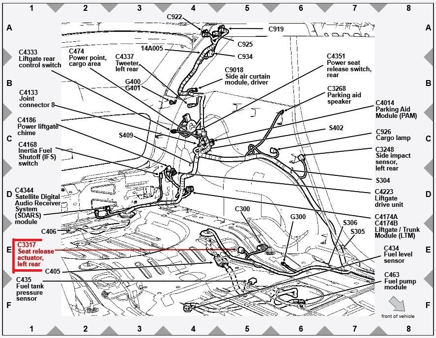
Hopefully by now, you have determined the root cause of your Edge's no-start condition. The connectors in your photos were attached to the left & right Rear Seat Release Actuators that facilitated the remote fold-down of the rear seat backs. Good luck!
-
Horn not working 2012 SEL
Haz replied to 12SEL's topic in Alarms, Keyless Entry, Locks & Remote Start
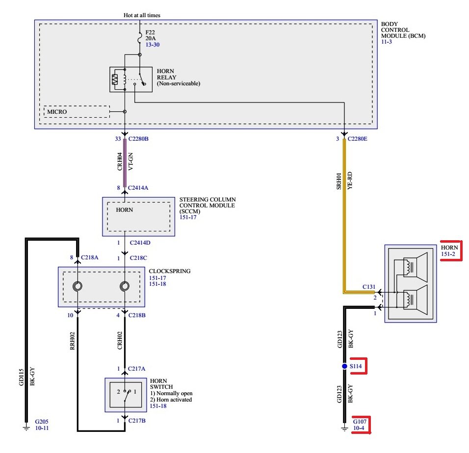
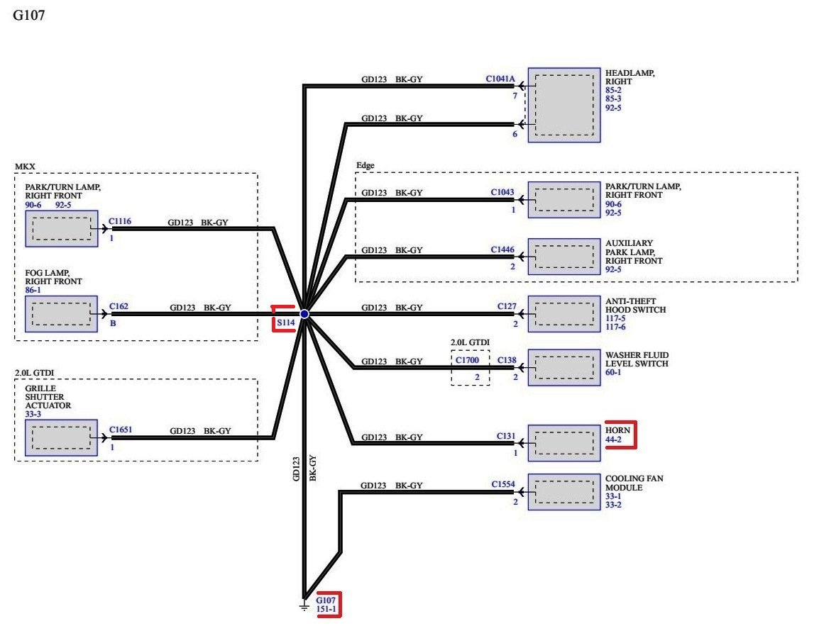
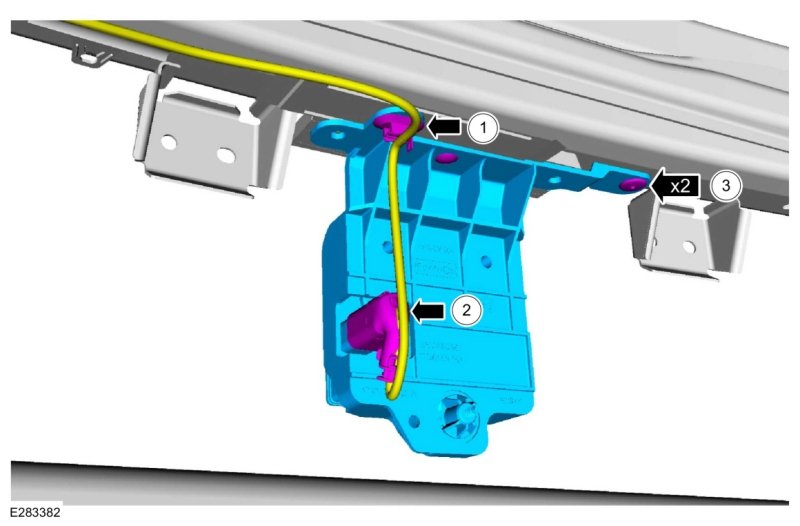
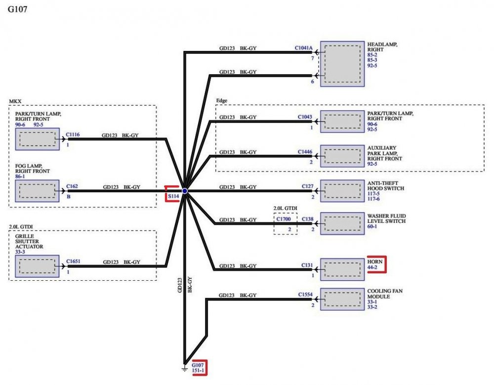
Just in case the aftermarket horn does not solve the problem, here are additional images highlighting the Horn ground circuit, ground wiring termination location, other components utilizing that same ground termination, ground harness location... Good luck!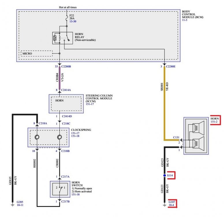

-
@omar302: Is your Sport equipped with HID headlights, and are you running the Forscan DRLs setting, where the turn signal element is lit when HIDs are not on and transmission is not in Park, or, is that not available to GEN 2 owners? This arrangement has been satisfying on our 2012 & 2015 GEN 1+ MKXs, though bulb changes do occur more frequently due to their near-continuous usage. Good luck!


AntennaInputsWiringDiagram-2019EdgeWorkshopManual.jpg.2d3471e44d14739240541d74a8a91245.jpg)