WWWPerfA_ZN0W
-
Posts
11,144 -
Joined
-
Last visited
-
Days Won
272
Content Type
Profiles
Forums
Gallery
Everything posted by WWWPerfA_ZN0W
-
Sorry to hear, this must be SO frustrating! You need to buy Mr Murphy a few drinks, it seems like, been ignoring him ... Whereabouts was the Edge hit? Front/rear/? The "battery" problem could be many things, unfortunately: A] An actual bad battery, especially if it is original to the Edge (very likely) B] Loose/corroded battery cable terminals (possibly loose from disconnection/reconnection during body work) C] A shorting component like an APIM or shifter D] Bad alternator E] Failing starter F] Shorted wiring (the most annoying issue to fix) Anyways, keep us updated! When the battery is replaced, the Battery Monitoring System needs to be reset so that the PCM knows it's new and learns the new battery's characteristics.
-
2009-10 Edge & MKX Recall - Fuel Tank related
WWWPerfA_ZN0W replied to WWWPerfA_ZN0W's topic in Recalls, TSBs & Warranty
I believe it is an expanded recall, but since the documents are not yet posted, can't say for sure 100%. -
Make sure SHOW NOTIFICATIONS is ON (#7 in the list above). That's been a very common fix after the 3.8 upgrade.
-
Saw this on another site: http://www.autoblog.com/2015/10/28/ford-mustang-edge-lincoln-mkx-recall/
-
2013 Edge SEL left rear brake dragging
WWWPerfA_ZN0W replied to wally67's topic in Brakes, Chassis & Suspension
What is the sound like? Whoosh? Hoot? Whine? Grind? Are the "silencers" on the calipers still good2go? -
2015 Ford Edge Engines: Everything You Ever Wanted to Know
WWWPerfA_ZN0W replied to Chipster's topic in EcoBoost
Actually, the difference at 15,000 miles would still be negligible if the V6 + regular is being compared to 2.0EB + premium. $1,833.33 vs $1,900 If you use the V6+ premium, yes, the cost at 15,000 miles would be $2,216.67. -
Follow the owner's manual. See if your driving style/conditions meet the NORMAL or SEVEREDUTY definitions, and then use that interval as guide. Or if you don't mind variability, you can use the Intelligent Oil Life Monitor function to tell you when the oil needs changing. Be sure to reset it once the oil change is complete. The servicing shop may or may not do it for you. Pg 455 of the manual: Your vehicle is equipped with the Intelligent Oil-Life Monitor system, which displays a message in the information display at the proper oil change interval. This interval may be up to one year or 10000 miles (16000 kilometers). When the oil change message appears in the information display, it is time for an oil change. Make sure you perform the oil change within two weeks or 500 miles (800 kilometers) of the message appearing. Make sure you reset the Intelligent Oil-Life Monitor after each oil change. See Oil Change Indicator Reset (page 263). If your information display resets prematurely or becomes inoperative, you should perform the oil change interval at six months or 5000 miles (8000 kilometers) from your last oil change. Never exceed one year or 10000 miles (16000 kilometers) between oil change intervals.
-
2015 Edge Sport Towing
WWWPerfA_ZN0W replied to built2prfctn's topic in Cargo, Hauling, Roof Racks & Towing
Congrats on the new Sport, Picturepro! -
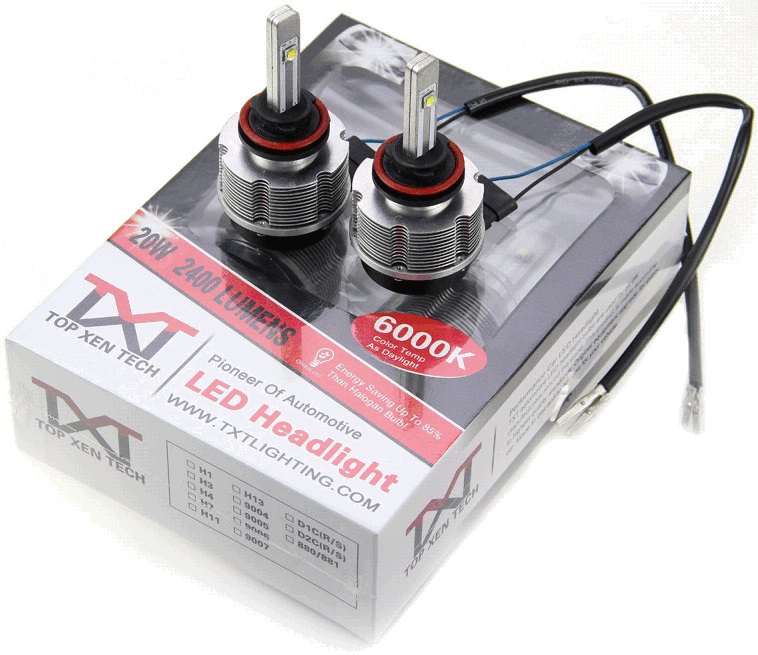
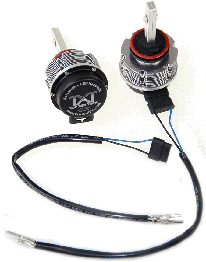
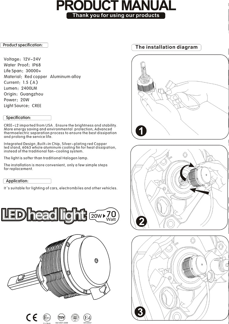
The LED unit plugs in just like a halogen bulb. The heatsink is outside the headlight assembly, as is the adapter cord to connect to the appropriate pigtail on the other end (9005/9006/etc). Never been "flashed". I will have to recheck my files, but the light pattern fits the same area as the halogen bulbs. I use separate LED bulbs for high beams, and it is very obvious when I have them on.
-
Hmm. Should be pretty straightforward removing the pivot arms. Remove the cap and there's a hexagonal bolt that holds down the pivot arm. Remove & presto! To install, tighten to 30 Nm (22 lb-ft). The only tip I know of would be to place a thick towel between the wiper blade and the glass to minimize any force exerted on the windshield.
-
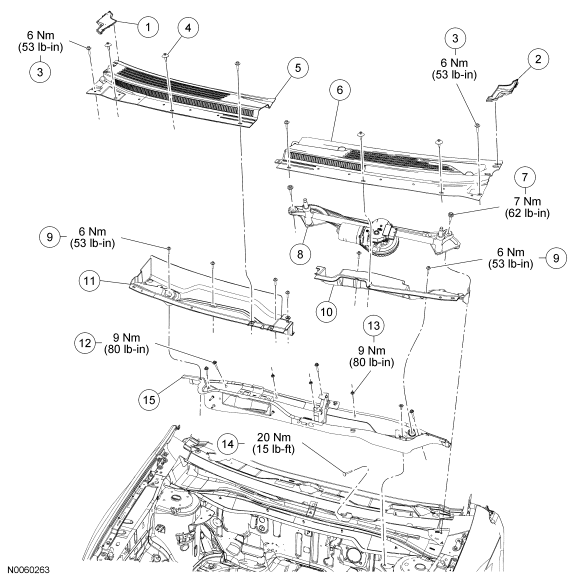
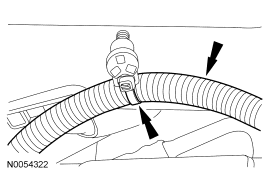
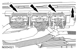
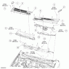
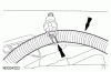
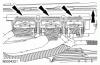
From the 2007 FSM (hopefully only have to remove the upper panel?): Item Part Number Description 1 020A26 RH cowl side outer panel 2 020A27 LH cowl side outer panel 3 W712648 Upper cowl grille panel screws (4 required) 4 N804837 Upper cowl grille panel scrivet (4 required) 5 02222 RH upper cowl panel 6 02223 LH upper cowl panel 7 17526 Wiper pivot arm assembly bolt (2 required) 8 17508B Wiper pivot arm assembly 9 W707257 Cowl panel extension bolts (6 required) 10 021A37 LH cowl panel extension 11 W707257 RH cowl panel extension 12 W710593 Lower cowl panel bolt (5 required) 13 W702751 Lower cowl panel nut (3 required) 14 W710309 Lower cowl panel-to-front of dash bolt 15 02106 Lower cowl panel Upper and lower cowl grille panel NOTE: The upper cowl panel grille must be removed before the lower cowl panel grille can be removed. Remove the LH and RH wiper pivot arms. For additional information, refer to Section 501-16 .Upper cowl panel grille Remove the RH cowl side outer panel.Remove the LH cowl side outer panel.Remove the 2 scrivets from the RH upper cowl panel grille.Remove the 2 bolts from the RH upper cowl grille panel and remove the RH upper cowl grille panel. To install, tighten to 6 Nm (53 lb-in). Remove the 2 scrivets from the LH upper cowl grille panel.Remove the 2 bolts from the LH upper cowl grille panel and remove the LH upper cowl grille panel. To install, tighten to 6 Nm (53 lb-in). Lower cowl panel grille Remove the wiper arm and wiper pivot shaft assembly. Disconnect the electrical connector. Remove the 2 bolts. To install, tighten to 7 Nm (62 lb-in). Remove the 2 bolts from the upper left lower cowl grille panel extension and remove the panel. To install, tighten to 6 Nm (53 lb-in). Remove the 4 bolts from the upper right lower cowl panel extension and remove the panel. To install, tighten to 6 Nm (53 lb-in). Disconnect the wiring harness from the retainer on the left front of the lower cowl grille panel. Disconnect the electrical connectors from the powertrain control module (PCM). Remove the evaporative purge valve and bracket from the center of the lower cowl panel grille and set aside.Remove the 5 bolts and 3 nuts from inside the lower cowl grille panel. To install, tighten to 9 Nm (80 lb-in). Remove the bolt from the lower cowl panel-to-front of dash. To install, tighten to 20 Nm (15 lb-ft). Remove the lower cowl grille panel and PCM from the vehicle.
-
2015 Ford Edge retractable cargo shade
WWWPerfA_ZN0W replied to kfletcher210's topic in Accessories & Modifications
Please post the part number if you have it/when you get it. TIA! -
2010 Ford Edge noise in front end
WWWPerfA_ZN0W replied to Gordon 2135's topic in Brakes, Chassis & Suspension
I really hope you didn't put the LV fluid in the power steering reservoir. For the 2010: Transmission Fluid: Mercon LV Power Steering Fluid: Mercon V Does the reservoir cap say to put in Mercon LV for power steering, by any chance? -
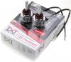
Got them off EBay last year, from a seller named itrendstyle. Don't see them or their product anymore for sale.

-
Been running LEDs in the headlights for quite some time now. No problems so far.
-
Is the lumen output per bulb or summed?
-
If lubing the various componentry didn't fix it, then probably time to take the panel off and look at all the fasteners real closely. A screw could literally have come loose over time, or a plug could have broken off, etc.
-
My hope that it is a seal is because that can be fixed pretty easily. If the vents are improperly placed however, there is a real problem. May be resolved by sealing the old vents and drilling new ones elsewhere/in another direction. Ford didn't have to design the Edge for submersion, but surely to withstand the rain that landlubbers can expect to get!
-
Certainly, if the parts can be sourced, they can be replaced. Nobody's dug into the physical layout of the SJB that I know of, though.
-
Imperial gallon measurement nets 30.9 mpg approx, while in the US, that would be about 25.7 mpg, still very very good!
-
Correct.
-
Could be a worn out wheel bearing, probably the left one, but can only tell on a lift. Also manifests as a grind or a howl or a roar. The fact that it happens at high speeds makes me think wheel bearing. Could be a tire also, happens from time to time, can try rotating the tires to see.
-
The SJB has to be replaced by a dealer or a shop with access to IDS scan tools. I am not saying that it IS the problem, because it could be wiring issues anywhere along the path.
-
The 2.7L Ecoboost is paired to the 6F55, but towing wise, the restrictions are not dissimilar to other vehicles. The Flex, however, has a rating of 4,500 lbs (same engine/drivetrain as the SHO) with a Class III pkg. The Explorer goes to 5,000 when properly equipped.
-
The turn signals/hazards are controlled by the SJB, not a relay. Do you have halogens only, or LEDs mixed in also? LEDs in the circuit can cause the SJB to act up. Principles of Operation The smart junction box (SJB) monitors the multifunction switch position by sending multiple voltage reference signals to the multifunction switch. When the multifunction switch is in the LH or RH TURN positions, or the hazard lamp switch is pressed, that input signal is routed to ground. When the SJB receives a request for a turn signal or hazard lamps, the SJB supplies voltage to the appropriate turn lamps. The timed on/off cycle is determined by the SJB and is set to flash approximately 80 times per minute if both the front and rear turn lamps operate correctly. If an individual turn signal lamp is inoperative, the SJB flashes the remaining turn lamp approximately 160 times per minute. Field-Effect Transistor (FET) Protection The SJB utilizes a FET protective circuit strategy for many of its outputs (for example, the headlamp output circuit). Output loads (current level) are monitored for excessive current (typically short circuits) and are shut down (turns off the voltage or ground provided by the module) when a fault is detected. A continuous DTC is stored at that time for the fault. The circuit will then reset after a customer demand of the function (switching the component on, battery saver being energized). When an excessive circuit load occurs several times, the module shuts down the output until a repair procedure is carried out. At the same time, the continuous DTC that was stored on the first failure will not clear by a command to clear the continuous DTCs. The module will not allow this code to be cleared or the circuit restored to normal operation until a successful on-demand self-test proves that the fault has been repaired. After the on-demand self-test has successfully completed (no on-demand DTCs present), the continuous DTC will have been cleared and the circuit function will return. Each circuit has three predefined levels of short circuit tolerance established in the module based on each circuits' capability. When the first or second level is reached, the continuous DTC associated with the circuit sets along with DTC B106E. These DTCs may be cleared using the Clear DTC operation on the scan tool as long as the fault itself has been corrected. If any of the circuits are shorted past the third level, then B106F sets along with the associated continuous DTC. This DTC cannot be cleared and the module must be replaced. The SJB FET protected output circuits for the turn lamp system are for the LH front turn lamp output and the RH front turn lamp output circuits. The rear turn lamps utilize the stoplamp circuitry and are also protected. For additional information regarding the rear stop lamps, refer to Stoplamps in this section.