Leaderboard


Popular Content
Showing content with the highest reputation since 04/05/2025 in all areas
-
Not lot of detailed info on this; only a handful of threads here. The procedure was pretty simple but has gotchas and other things I didn't really care for. For example the torque on the PTU fill plug, you'll never get 33 ft/lbs on that. I stopped turning before I got to 28 ft/lb and noticed the plug was deeper than when I first took it out and stopped. There's also no way, as mentioned in another thread here, that you can completely remove the PTU cooler without removing the crossmember there. You can however, pull the cooler out far enough to drain the fluid. Make sure not to screw up the o-ring on the cooler though, or you will be dropping the crossmember. Those of you with just a plug here and no cooler don't have to worry about this as your plug comes right out. Here's the fill plug and PTU cooler with the stud/nut showing. When I opened the fill plug not even a dribble of fluid came out. I had to use a combo of 1/4" 8mm socket and 8mm flex head closed end ratchet on the nuts. Or you can drop the exhaust. I kept the 1-piece stud/nut and just reused them. The PTU cooler pops out easily, or as much as it can before hitting the subframe. The coolers metal rod elements extend the length of PTU basically. Here she is draining. You can see the o-ring - do not mess it up. Brake cleaner will be your exhausts best friend. I'd say I spilled an ounce or more other than what's in the container but I tried to measure what came out of it. In the sun. Didn't look too bad I thought for ~35k miles but idk. Reinstalled PTU cooler and cleaned everything up. Inserted the stud/nuts and torqued to 97 in/lb Here's what I use to fill up transmissions and differentials. Just a regular water vacuum pump you can get on Amazon for $10. Easy peasy no mess no pumping just press a button. I put as much oil as it would take until it started streaming out. Then I spun the tires several times by hand and waited a few more minutes before pumping more fluid in. When the stream stopped and turned into a drip I put the fill plug back on with some thread sealant. Like I said above I don't like how Ford says 33 ft/lbs on the fill plug - that's not happening at least on mine. All cleaned up and done. I'll check the level again in 100 miles or so. The fill plug is inserted further than it was from the factory at 28ft/lbs. Be careful with aluminum. And that's pretty much it. It should take about an hour if you have access to a lift. As with everyone else, I have no idea why Ford couldn't put a drain plug other than to purposely let PTU's eat themselves after the warranty period.8 points
-
I am about to close a deal on a 2019 Edge Titanium Elite. I'm excited to learn more about it. I am a retired Ford parts manager, but have never owned an Edge.
 7 points
 -
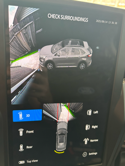
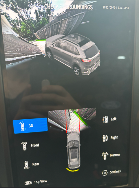
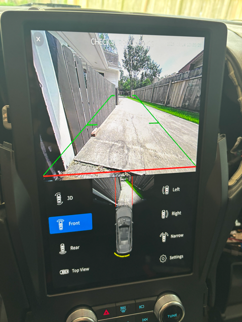
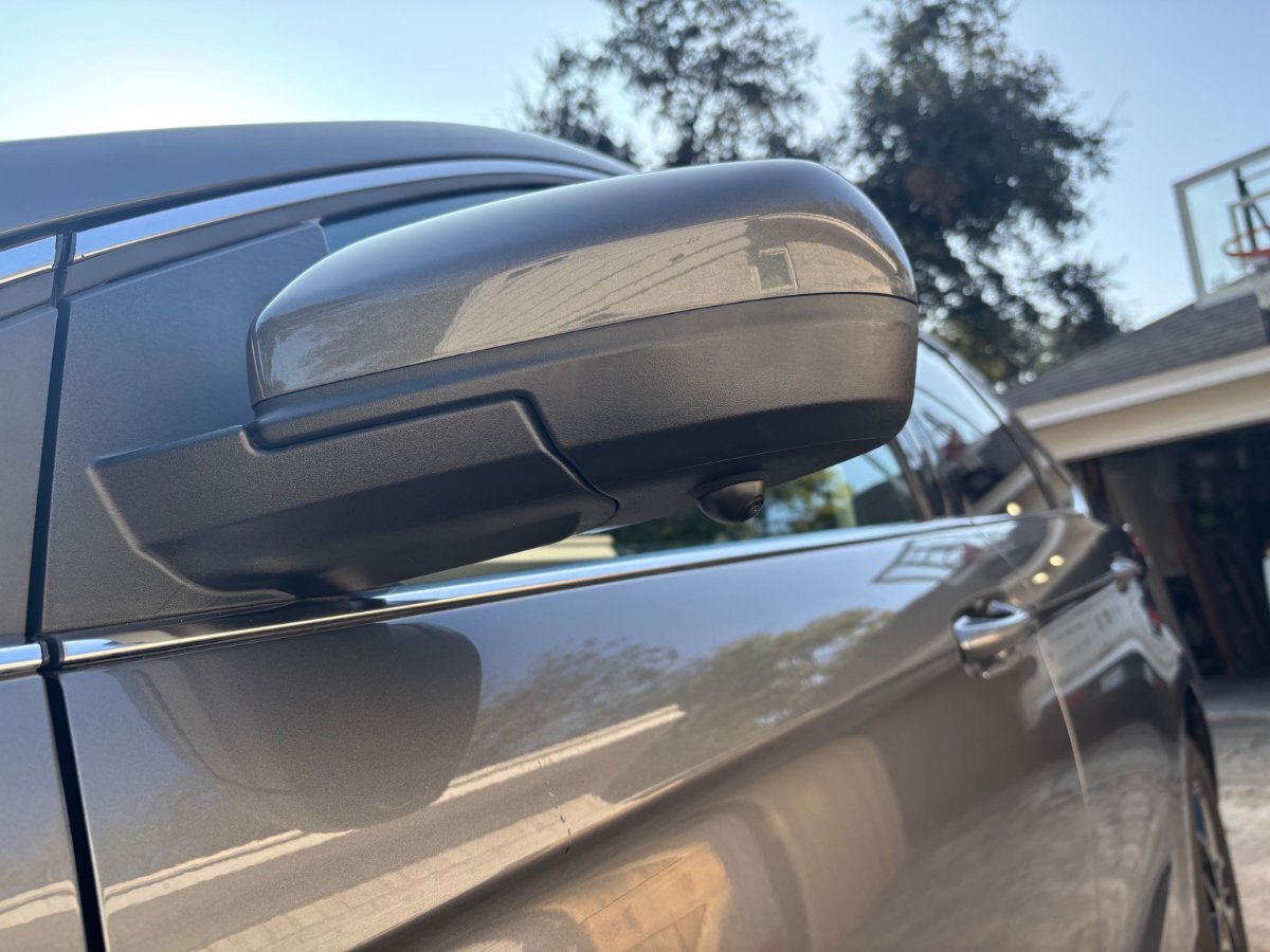
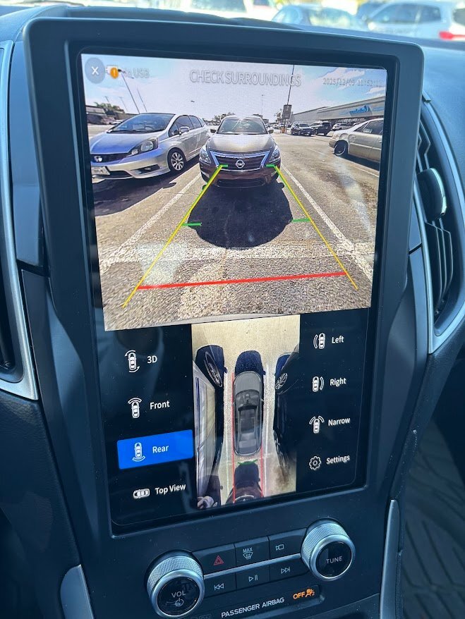
Hello everyone, I’ve been following this thread with a lot of interest — great work from all of you digging into the 360 retrofit! I’ve been wanting to achieve a similar result, but I decided to take a different approach. I went with a third-party 360 AVM kit and set it up to integrate with the SYNC screen on my 2023 Ford Edge. There really isn’t anything compatible out of the box with the Edge, but I noticed the Edge and Ranger share similar hardware and modules. And notice I said similar — not the same. It’s been a long process — I’ve done tons of research and a fair amount of trial and error to figure out the video inputs, CANBUS integration, and DIP switch configurations needed to get everything displaying correctly with the factory screen and triggers. With this I do have dynamic guidelines, parking sensors, multiple views along with the top-down bird view. Also I did retain the factory camera and camera view, and I can jump between factory view and 360 kit view. It’s still a work in progress, but going this route gives me more flexibility compared to being locked into the OEM restrictions. I’ll share more updates as I continue refining the setup. Next steps will be to mount all the cameras
 7 points
 -
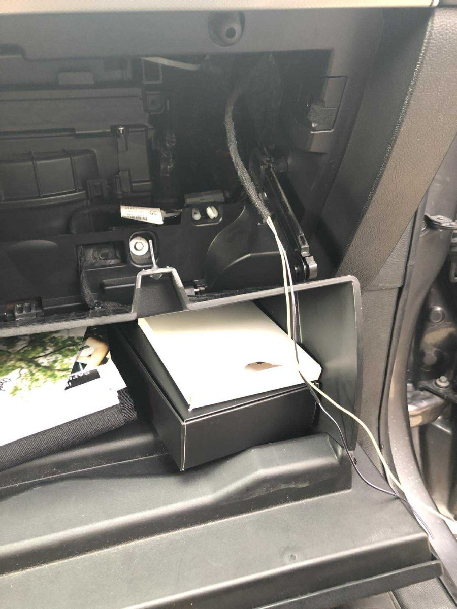
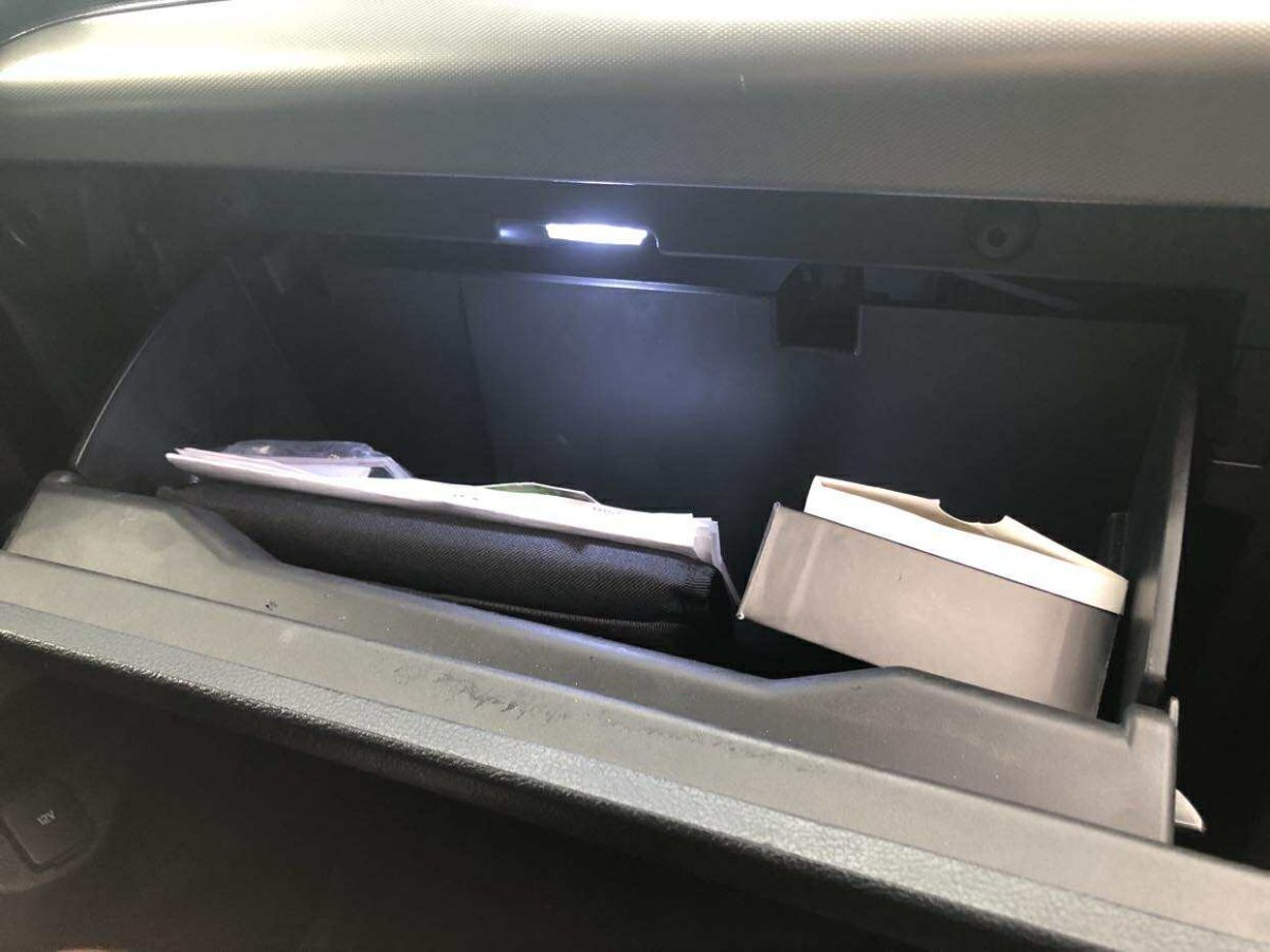
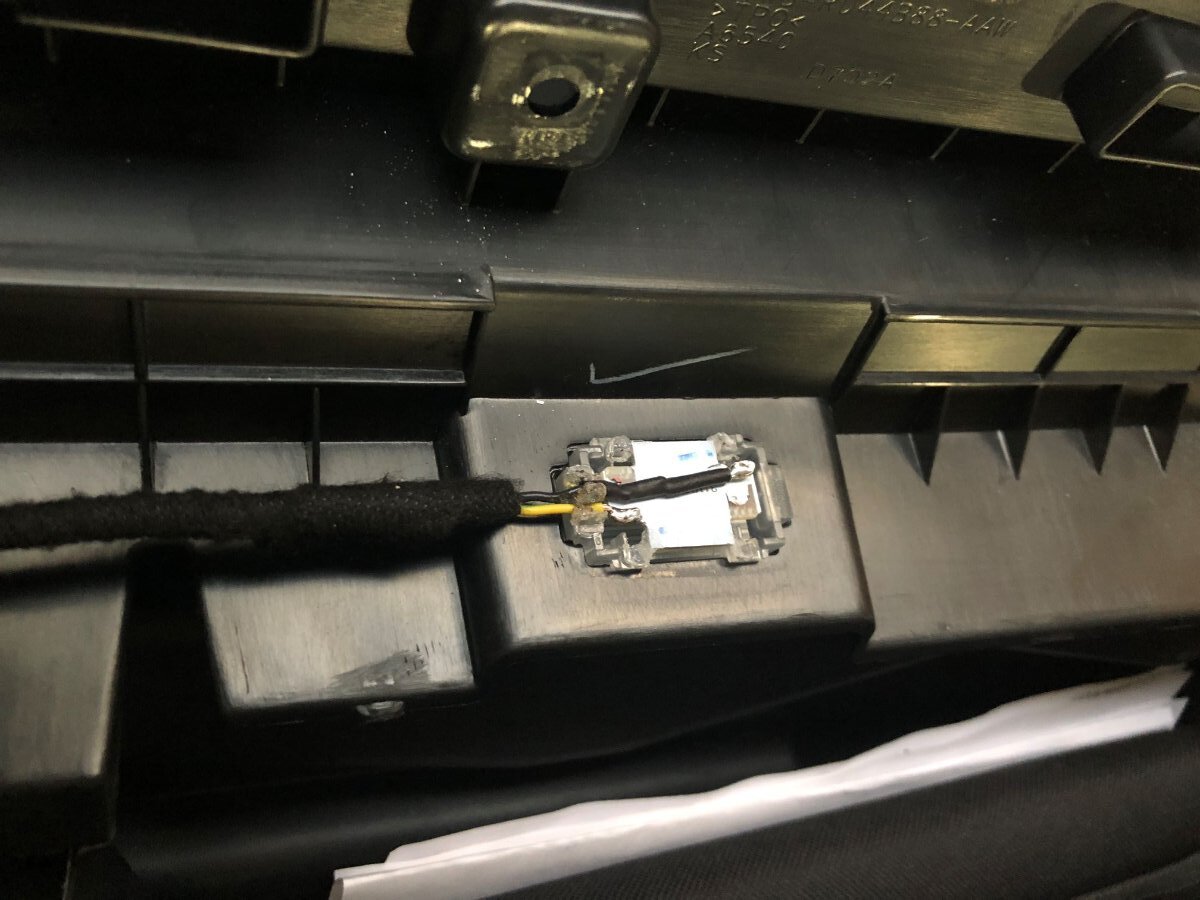
The little things matter 😉 Added glove box compartment light back in the Edge. Don't know why Ford deleted it in the first place. Scored a 2017 Edge glove box lamp harness and damper from the junkyard. With a little bit of DIY (dremel action & soldering), swapped out the LED PCB for a brighter aftermarket one. I made a T-harness to tap into the passenger side (visor) vanity mirror lamp circuit. Ran that down the psngr side A-pillar all the way to the glove box.


 6 points
 -
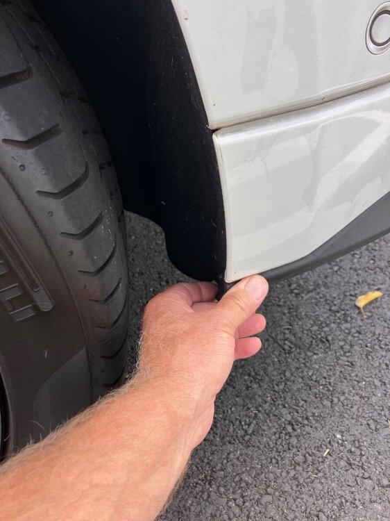
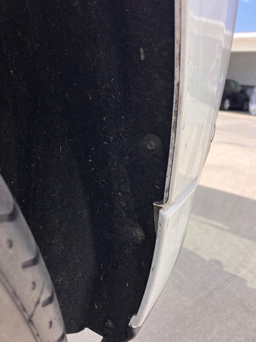
Found it! Tighten the bolts holding the fabric material to the fender well and it is gone! I sent you a personal message and here are the pictures. Jiggle the area where my hand is and you should hear the sound. tighten the bolts about a half turn.
 5 points
 -
alright, so its lane changing, never had awd so i kept looking at awd symptoms and solutions, i found it turned it off will drive tomorrow to see what happens technology is killing/saving me if you ever need help with a 73-79 f100 let me know, simplicity is awesome thanks for the help could not have done it without your insight5 points
-
I believe your assumptions are incorrect. The IAT isn't sensitive to fouling. These days an MAP has taken the place of the MAF - the MAP is way less sensitive to fouling compared to the MAF and its very rare that it requires cleaning. My 2017 2.7L has 123K miles on it and its never needed carbon removal. .4 points
-
That press release looks to me like they planned to relabel they BG44K in the Ford branded package. I can vouch for the 44K stuff in the 2.7. Having used it, the stuff is legit.4 points
-
Following a Google search it seems it was not a rumor, but an actual agreement. BG's press release announcement here. Attached is a Motorcraft leaflet. Parts can be found online, examples: PM-44-A here. PM-30-K here. Chemical_Product_Flyers.pdf4 points
-
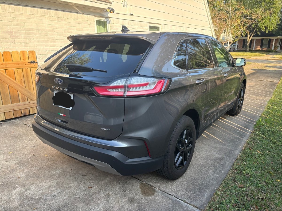
I finally wrapped up the full camera system install on my Edge. Front Camera I swapped out the factory grille for a black one that already had the camera mount integrated. Definitely the cleanest way to do it — no drilling and a perfect OEM-style fit. Side Cameras The side mirrors were straightforward. Routing the wiring and lining up the cameras was easy. Just a bunch of plastics to remove. Rear Camera This one took the most work. Like I mentioned in my previous post I wanted to retain the factory camera and system, and just add the new camera for the 360 view. I had to get creative. I decided to embed the camera in the logo. Marked and dremel’d out a custom recess behind the Ford emblem. Mounted the camera flush and secured it internally. Ran the wiring through the hatch. Calibrated the image afterward so the lines lined up correctly Honestly, this was the toughest part, but I’m happy with how the end result looks. I think I could have done a better job, or maybe could have thought of something else. But also I really wanted to finish the project. I think I'm going to redo the calibration after the holidays to get a better results but overall it's good. If anyone has ideas for cleaner mounting, I’m all ears.


 4 points
 -
Wanting to spend a few hundred dollars wisely? Drive through the poor section of your town and drop 30 $10 dollar bills out the window or, pick an Angel off the Christmas Tree @ the mall. Watch the video before you spend your hard earned $$$$!4 points
-
Hello fellow edge owners. I recently purchased this 2020 Ford Edge TITANIUM with 22k miles. I owned a 2011 a few years ago, but had to sell that off due to my growing family. Love these cars. Located in the Philadelphia, Pa. region.
 4 points
 -
I wanted to provide some closure on my whine/roar. After spraying the center bushing with lubricant and the whine/roar going away, I pulled the trigger and ordered a new center bushing. I used ramps on the passenger side to have the length of the vehicle up. I had to drop the exhaust, prior to cat (had to grind off the bolts), I then jacked up the front driver side to get the wheel enough off the ground so I could turn the driveshaft. I did put the transmission in Neutral, with the parking brake on and the rear driver wheel chalked. I removed the bolts holding the shaft on. The ends were "stuck". I sprayed with penetration fluid. I used some force, and mistakenly pulled the dust housing off the rear (very bad move on my part). I finally had to use a chisel and tap it out. The front came out with no issues. No matter the videos I watched. the amount of force I applied or the penetration fluid I applied, the shaft was NOT separating. After looking more at the rear of the shaft, I realized that by pulling off the dust cover, it was going to be an issue if I was able to get it back together. I had to order a new driveshaft. In the meantime, we drove the car for 2 weeks without a drive shaft with zero issues. No check engine lights nor performance issues that I could tell. I installed the new driveshaft, with the new center bushing and it's back to normal. No whine at all. At the end of the day, l spent a lot of time on my back and learned some lessons, but I think I still made out spending less than going to the dealer. I hope this helps someone.4 points
-
While the tips are in shadows, they look to be burning correctly, the tips worn round, and the end of the ground strap eroded, so certainly time to get it done. I did mine earlier just to get it done during a good time to work, between long drives, weather cooperating, etc. I did mine at 82k, a little erosion on the ground strap, but the precious metal tip was still square, could have gone much much longer, but for how cheap it was to do, if I pull them I replace them.4 points
-
Also, as far as I know, the oil life monitor also takes into account time with the maximum time being 12 months. So if you change the oil as suggested above at 50%, you would be more certainly changing the oil at no more than 5,000 mile or 6 months from when it was last reset. Or you can interpolate the interval you want, knowing that 100% means 10k miles or 12 months. For example, 60% oil life balance would mean 4k miles or 4.8 months.4 points
-
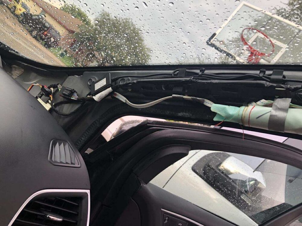
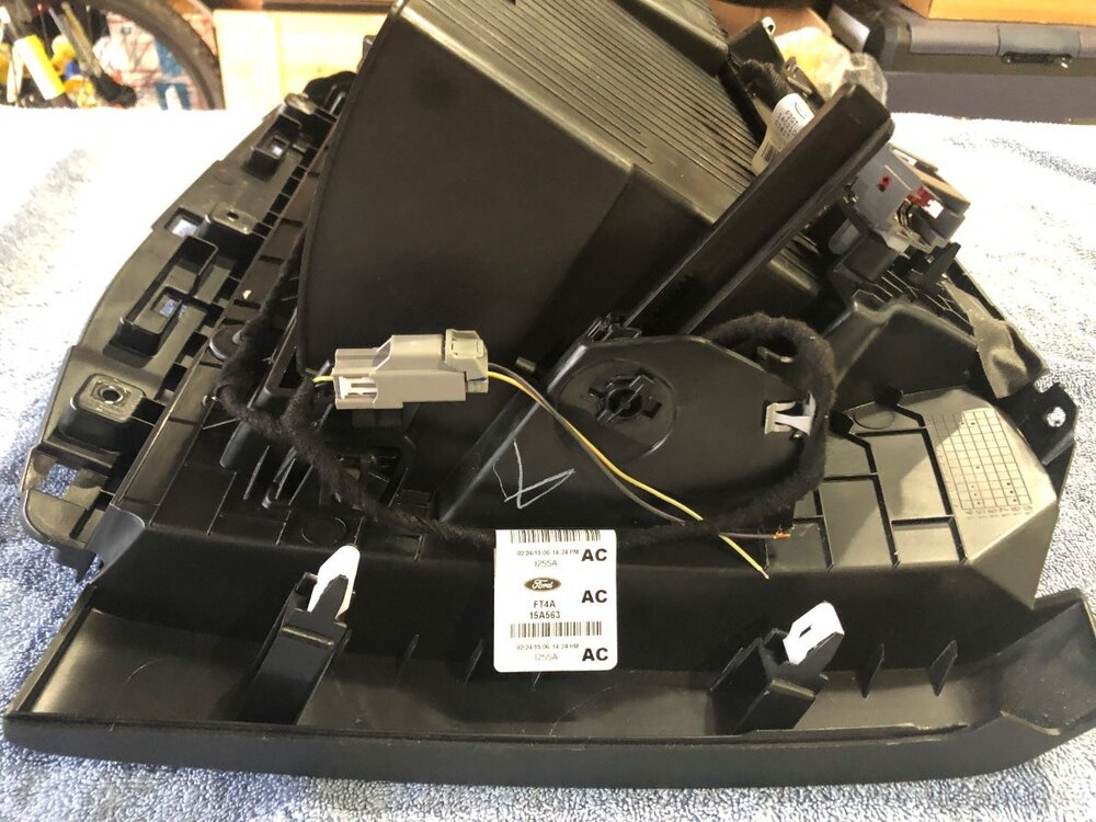
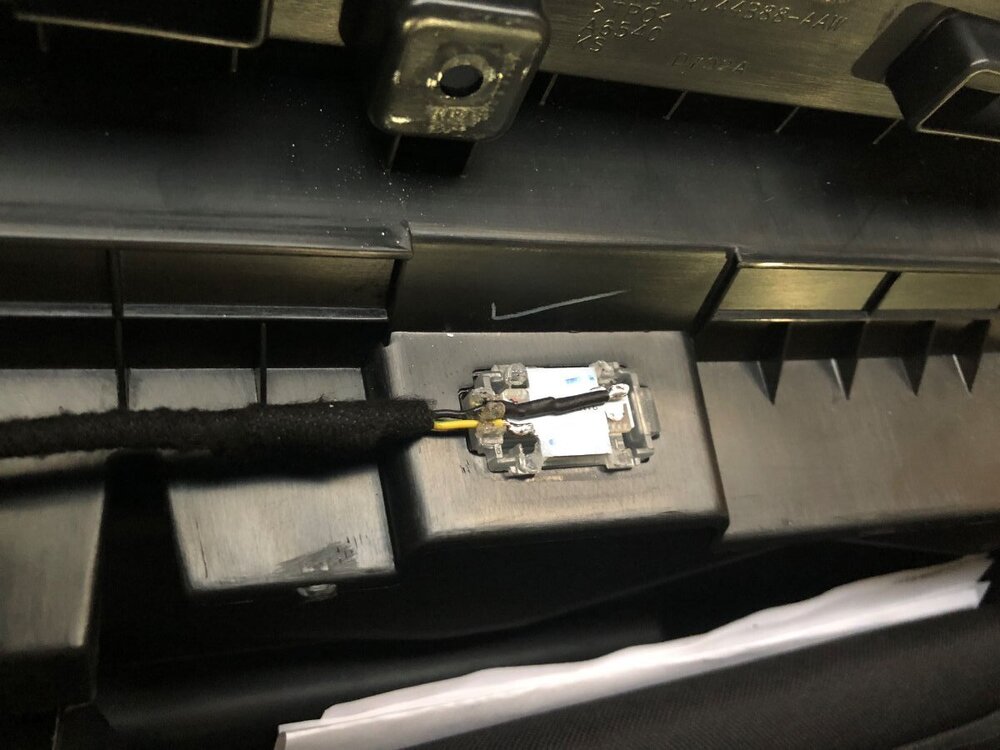
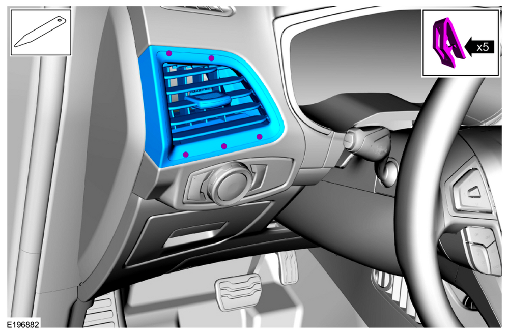
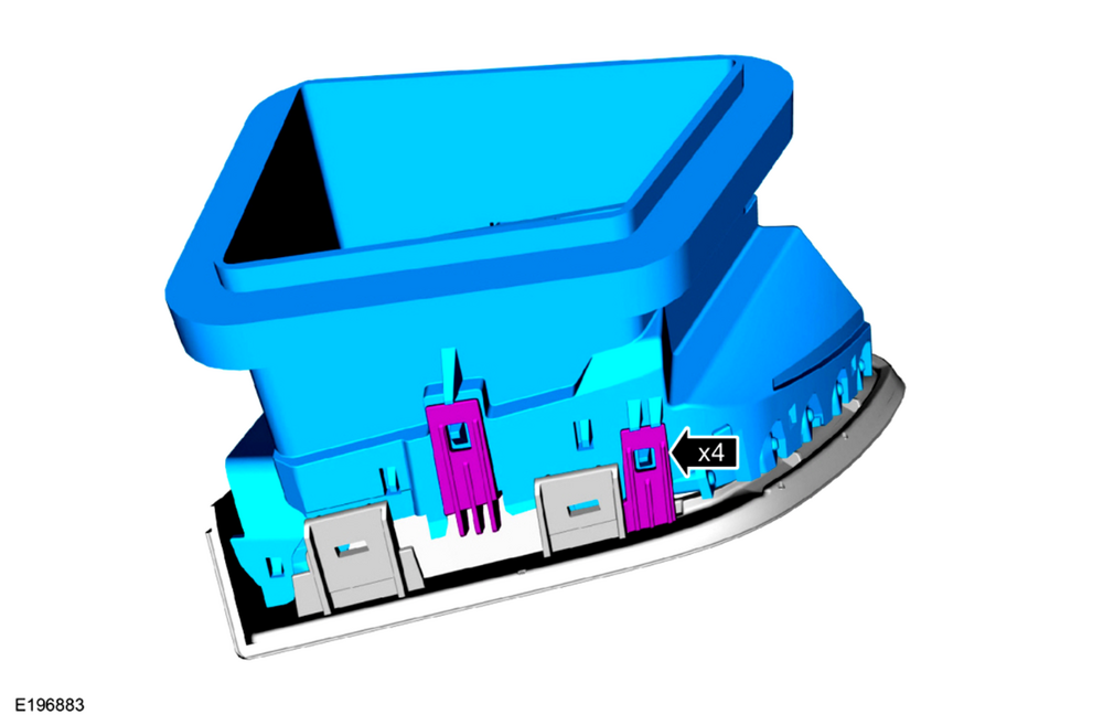
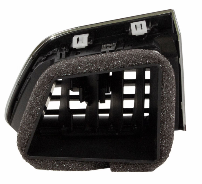
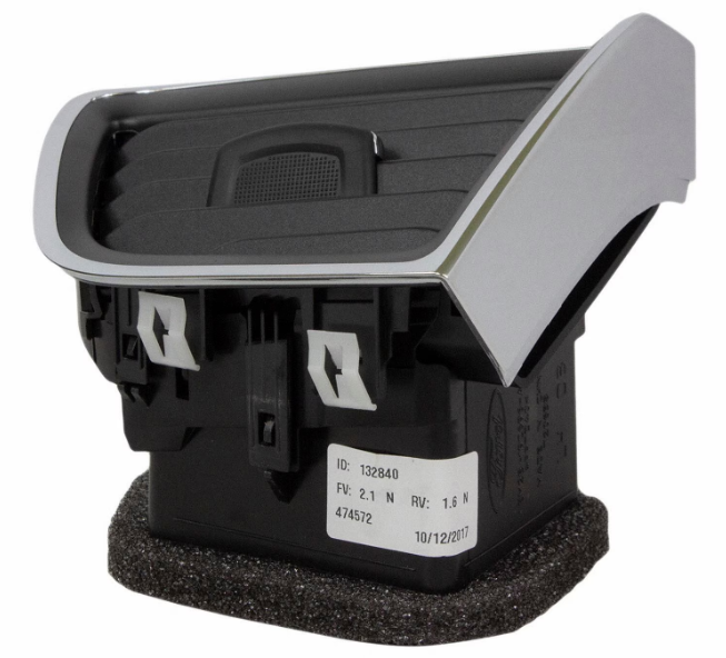
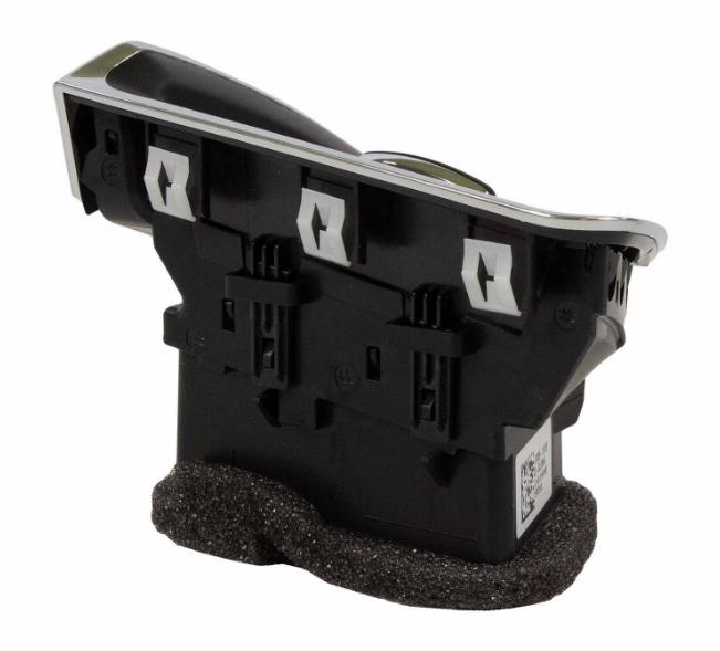
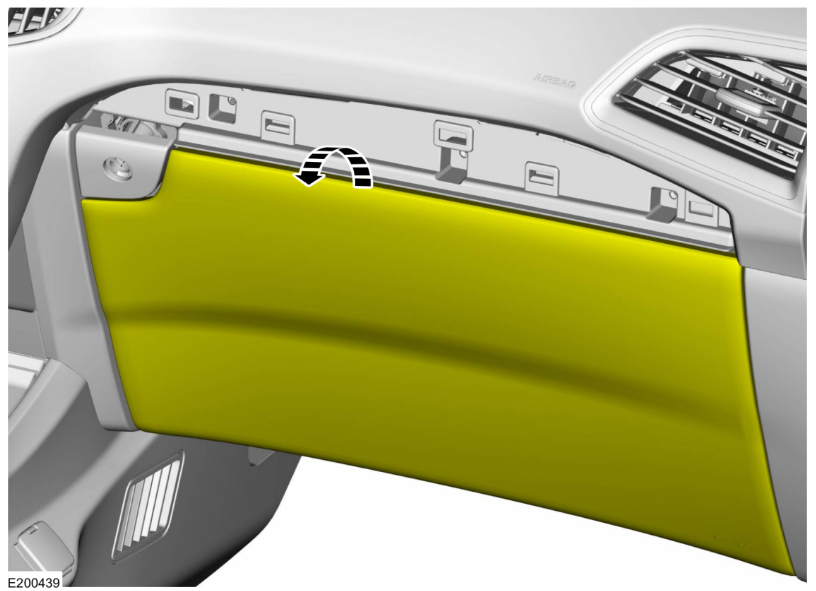
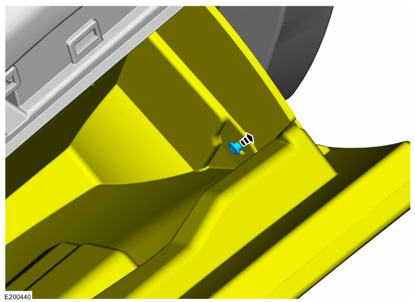
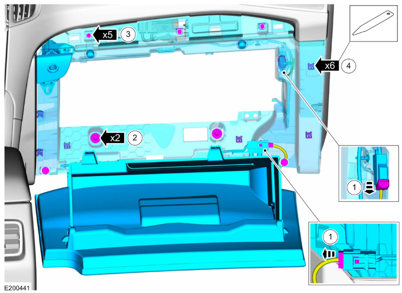
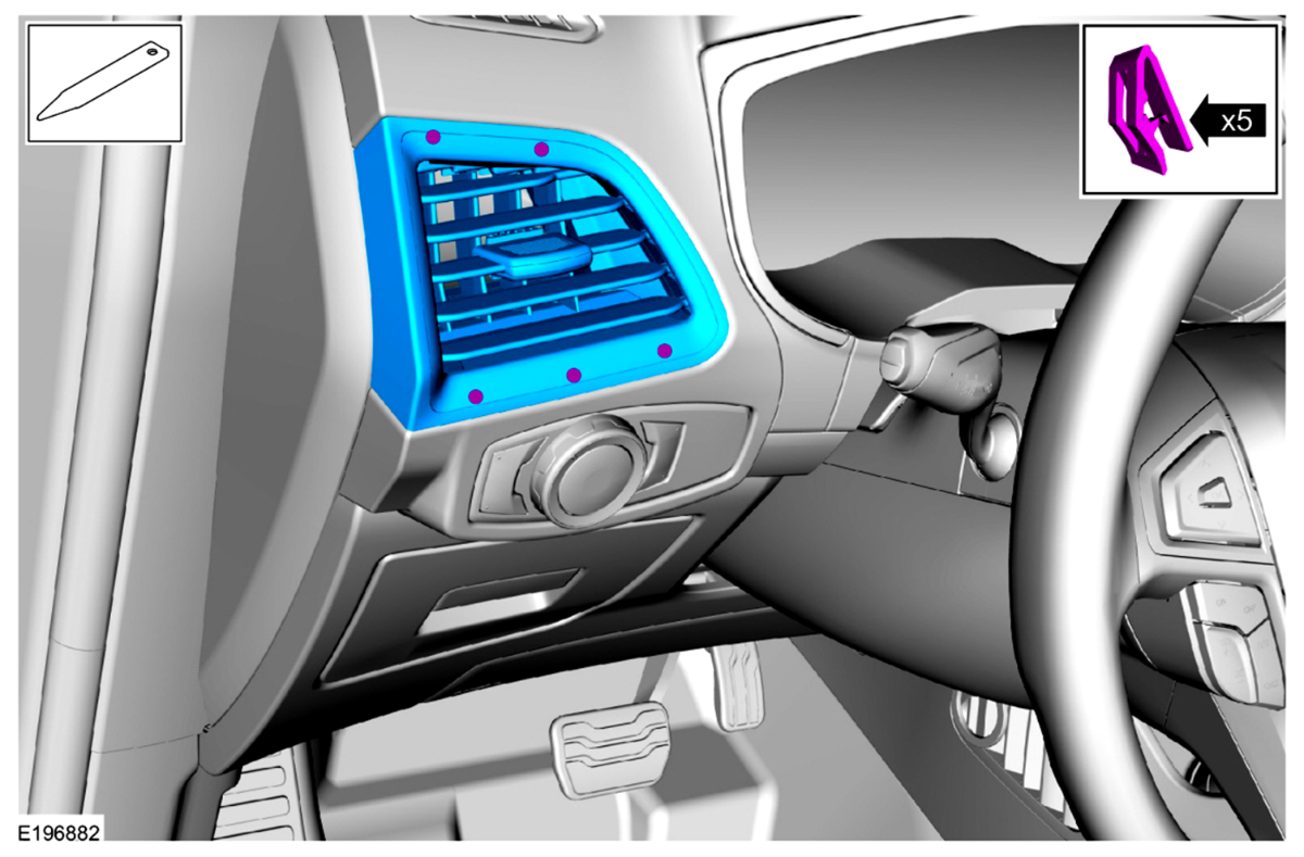
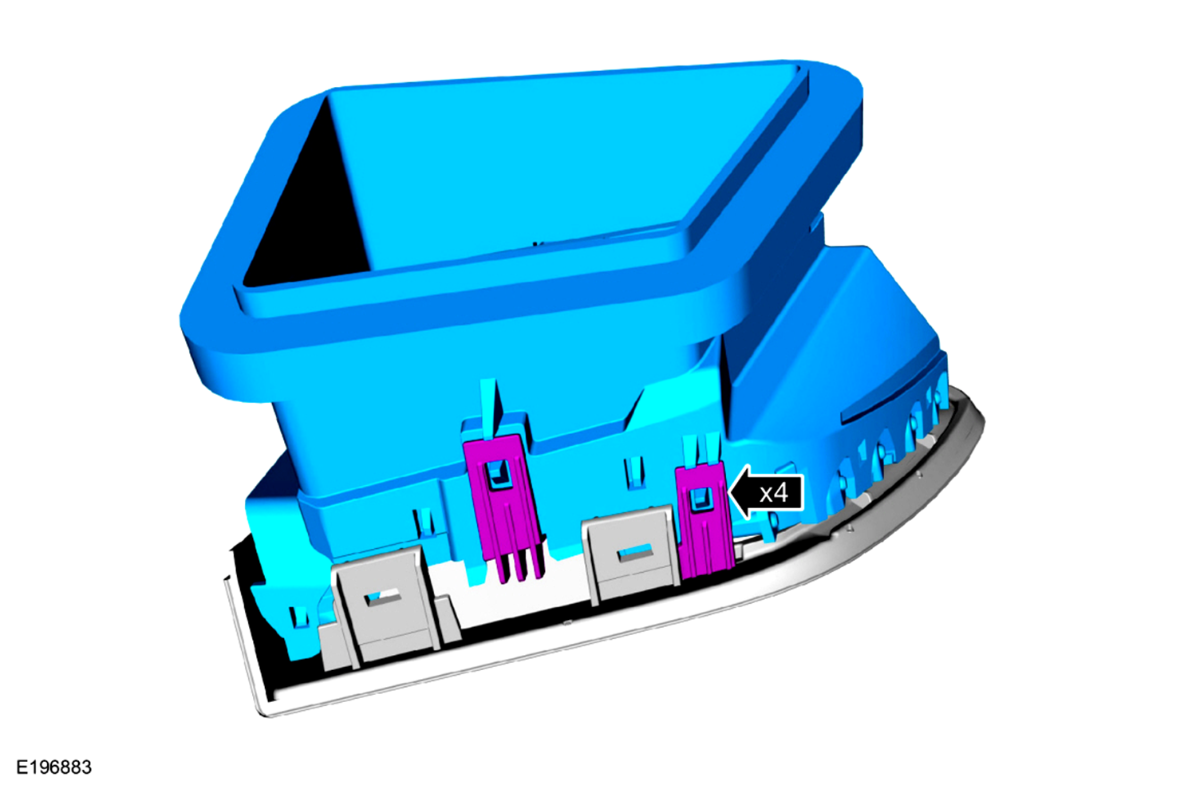
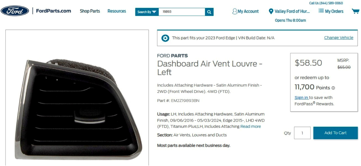
Welcome to the Forum @Jetboy47! The following is the Workshop Manual removal and installation procedure, which is also attached below as a PDF file... Driver Side Register Special Tool(s) / General Equipment Interior Trim Remover Removal Release the clips and remove the LH instrument panel finish panel. Use the General Equipment: Interior Trim Remover Release the clips and remove the driver side register assembly. Installation To install, reverse the removal procedure. Ford's online parts-selling site provides photos showing fuller detail of the retaining clips... Link to this FordParts webpage Good luck! Driver Side Register - Removal and Installation - 2022-2024 Edge Workshop Manual.pdf

 4 points
 -
I did the larger rotor swap a few months ago. The brackets were readily available on Rock Auto to use the standard non ST calipers. I felt that the ST calipers would be too much change for a vehicle that has Adaptive Cruise with Stop and Go. The master cylinder even for the AWD rotors versus FWD is different, a lot more things are different for the ST and ST PP brakes. I also didn't go with drilled/slotted since this is both our daily driver and our vacation vehicle. I have around 6,000 miles on the new brakes and all is wearing well, all advanced braking things like stop and go adaptive cruise, ABS, etc work, and they have been hammered on and no fade in the mountains as before. Make sure you have a large enough spare for the front, or know you will be putting the spare on the rear if you get a flat in the front. I found a relatively cheap 18 inch spare from an MKX.4 points
-
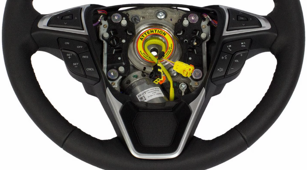
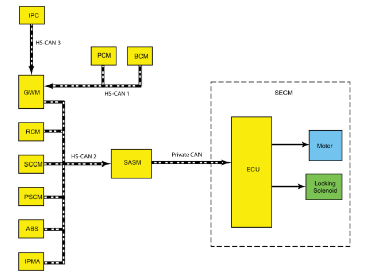
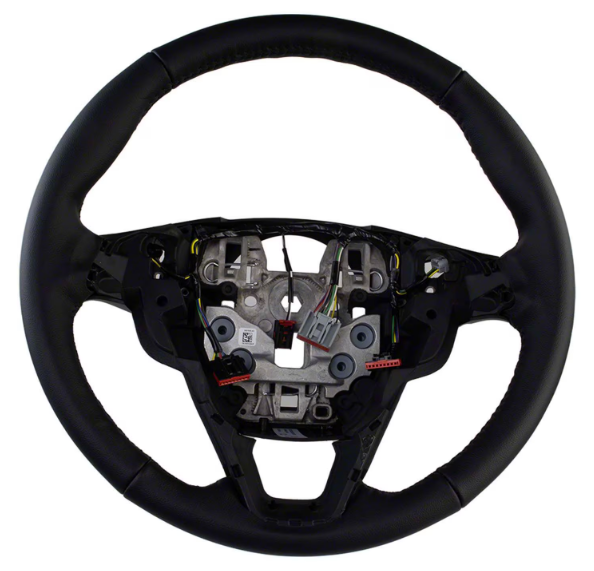
The closed-spoke steering wheels contain the motor for Adaptive Steering, as described in the 2019 Edge Workshop Manual... Adaptive Steering - Overview The adaptive steering system provides steering assist to the driver by dynamically changing the steering ratio between the steering wheel and the road wheels, thereby reducing the number of steering wheel turns required to turn the road wheels. This is accomplished through the use of a motor, worm gear and toothed hub. All adaptive steering system components are inside the steering wheel, behind the driver air bag. Additional technical detail on Adaptive Steering, from the Workshop Manual... Placing your device cursor over underlined acronyms may yield full-words descriptions of the acronyms. Adaptive Steering - System Operation and Component Description System Operation System Diagram Network Input Message Chart SECM Network Input Messages Broadcast Message Originating Module Message Purpose ABS active ABS module Used to inform the SECM an ABS event is taking place. Active front steering request ABS module Used to request steering angle changes for stability control events. EPAS fail PSCM Used to inform the SECM of an EPAS or PSCM failure. Lane keeping system status IPMA Informs the SECM of the current lane keeping system status. Odometer master value IPC This message is sent to the GWM and then to the SECM . Provides the SECM with the current odometer value in kilometers. Power pack status PCM This message is sent to the GWM and then to the SECM . Used to inform the SECM of powertrain status; OFF-torque not available, ON-torque not available, Start in Progress-torque not available, ON-torque available. Restraint impact event status RCM Informs the SECM of airbag deployment and fuel system cutoff due to a vehicle impact event. Stability control event in progress ABS module Used to inform the SECM a stability control event is taking place. Steering wheel angle ABS module Provides the SECM with steering wheel angle information for clear vision compensation. Steering wheel heat request IPC This message is sent to the GWM and then to the SECM . Informs the SECM the driver has requested the heated steering wheel to be activated. Transport mode BCM This message is sent to the GWM and then to the SECM . Used to confirm the vehicle is in normal operation mode, factory mode or transport mode. Turn signal status SCCM Informs the SECM of the current turn signal status; LEFT, RIGHT or OFF. Vehicle braking command ABS module Used to inform the SECM of vehicle braking. Vehicle configuration information BCM This message is sent to the GWM and then to the SECM . Provides the SECM with the current vehicle configuration (central car configuration). Vehicle speed PCM This message is sent to the GWM and then to the SECM . Used to inform the SECM of the current vehicle speed. Vehicle yaw data ABS module Provides the SECM with vehicle yaw data for clear vision compensation. Adaptive Steering System The SECM controls the functions of the adaptive steering system and communicates with other modules through the SASM over the HS-CAN2 . The SECM and the SASM communicate over a private CAN . To activate, the SECM requires battery voltage, ignition voltage and must communicate with other modules over the HS-CAN2 . The SECM must also receive the power pack status message from the PCM in order to activate. The SECM uses a motor to turn a toothed hub connected to the steering shaft to add or subtract incremental turns to the driver steering shaft input. At low speeds the same steering input from the driver delivers more front wheel angle, providing more low-speed agility. Low speed maneuvers require significantly less steering wheel rotation. At high speeds, straight line driving precision is increased, providing the driver with an improved highway driving experience and feel during moderate-to-high-speed cornering. As the driver turns the steering wheel, the SASM detects the speed and direction of the steering wheel rotation and transmits this information to the SECM over a private CAN . The SECM responds by activating the motor in the appropriate direction and speed to assist in turning the front wheels and reducing the necessary number of steering wheel turns required by the driver. The SECM is self-monitoring and is capable of setting and storing Diagnostic Trouble Codes (DTCs). Depending on the nature of the DTC , the SECM may engage the adaptive steering lock and may send a request to the IPC to illuminate the adaptive steering system warning indicator and display a message in the message center alerting the driver of a potential adaptive steering system concern. The warning message is sent over the HS-CAN2 to the GWM where it is converted to a HS-CAN3 message and forwarded on to the IPC over the HS-CAN3 . Adaptive Steering Lock The adaptive steering system is designed with a locking device. While the lock is engaged, the steering system is set to a fixed (1:1) steering ratio. A sound may be heard when the vehicle is started or shut off as the lock is disengaged or engaged and a slight movement of the steering wheel may be noticed while the locking action is taking place. If the vehicle loses electrical power or the SECM detects a fault while driving, the lock is engaged. Extreme operating conditions may also cause the SECM to engage the lock. This strategy prevents overheating and permanent damage to the adaptive steering system. Typical steering and driving maneuvers allow the system to cool and return to normal operation. While the lock is engaged, it is possible the steering wheel may not be straight when the vehicle is driving straight ahead and the driver may notice the steering wheel angle or "clear vision" may be off-set. The locking solenoid also engages when the ignition is set to ON and the driver door is closed, this prevents the steering wheel from turning unnecessarily while the system is off and affecting steering wheel clear vision. The locking solenoid disengages once the engine is started. Heated Steering Wheel The SECM is also the controlling ECU for the heated steering wheel system. For additional information on heated steering wheel functionality, Refer to: Steering Wheel and Column Electrical Components - System Operation and Component Description (211-05 Steering Wheel and Column Electrical Components, Description and Operation). Component Description Adaptive Steering Locking Solenoid The locking solenoid is a normally engaged (locked) solenoid which requires a voltage input to disengage (unlock). This provides a fail-safe in case of SECM or adaptive steering system failure. Adaptive Steering Motor The adaptive steering motor is a reversible, variable speed motor with an attached worm gear. The motor is internal to the steering wheel and is serviced with the steering wheel. SECM The SECM is the ECU for the adaptive steering system. The module monitors all sensor inputs and HS-CAN2 messages relating to the adaptive steering system and directly controls the output of the adaptive steering motor. The SECM is internal to the steering wheel and is serviced with the steering wheel. Conventional Edge steering wheel... Good luck!
 4 points
 -
And i bought it-a white SEL with a few options-cold weather package/trailer towing package/activex seats. Guess it will have to do-replacing a 2019 SEL with same options but with Nav and convenience package.4 points
-
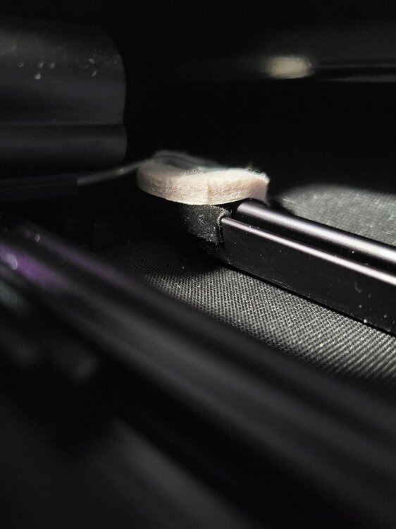
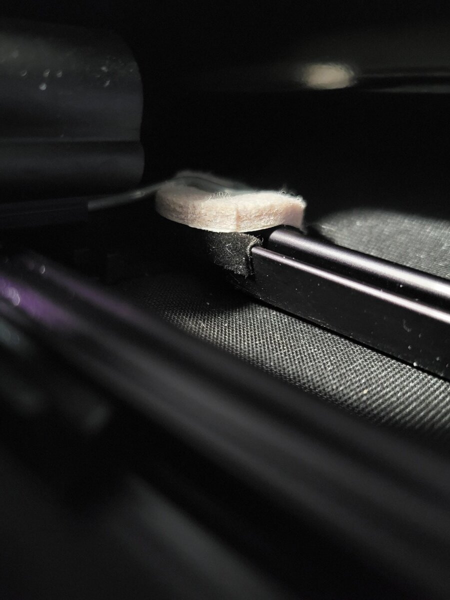
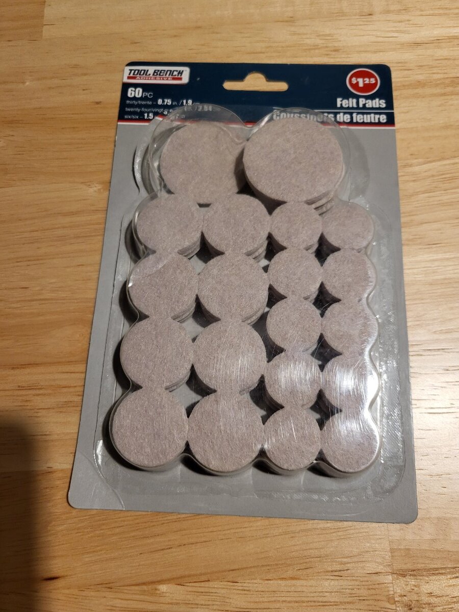
I think I found an easier solution to this issue. I was able to slide a screw driver under the clip and rotate it a little to lift it up. I then slid a thick piece of felt under the end of the clip and dropped it back down. I purchased a pack of those round stick-on felt pads that go on the bottom of kitchen chair legs from the Dollar Tree. The one I used was the size of a nickel. The very annoying tick is completely gone!!!!:) I had to redo this felt pad solution because it eventually compressed too much and the rattle came back. I ended up using a round piece of plastic about the size and thickness of a nickel with felt stuck to both sides. Just sticking felt to both sides of an actual nickel would also work well.
 4 points
 -
Link to this FordParts webpage Good luck!

 4 points
 -
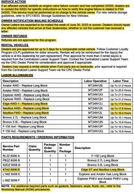
SSM 53601 2020-2023 Explorer/Aviator, 2020-2025 Police Interceptor Utility, 2020-2025 Escape/Corsair, 2022-2025 Maverick, 2024-2025 Nautilus - Hybrid - Illuminated MIL With DTC P2450:00 Stored In The PCM Some 2020-2023 Explorer/Aviator, 2020-2025 Police Interceptor Utility, 2020-2025 Escape/Corsair, 2022-2025 Maverick, and 2024-2025 Nautilus vehicles equipped with a hybrid powertrain may exhibit an illuminated malfunction indicator lamp (MIL) with diagnostic trouble code (DTC) P2450:00 stored in the powertrain control module (PCM). This may be due to an evaporative emission system concern or may also be caused by the customer overfilling the fuel tank. If this condition occurs, perform normal diagnosis per Workshop Manual (WSM) Section, 303-13 and repair as necessary. Inform the customer that the condition may have been caused by overfilling of the fuel tank and to not top-off the fuel tank when the fuel pump nozzle automatically shuts off for the first time. Refer the customer to the Fuel and Refueling section of their Owner Manual for additional information.4 points
-
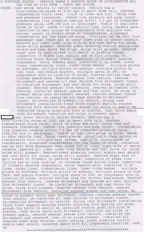
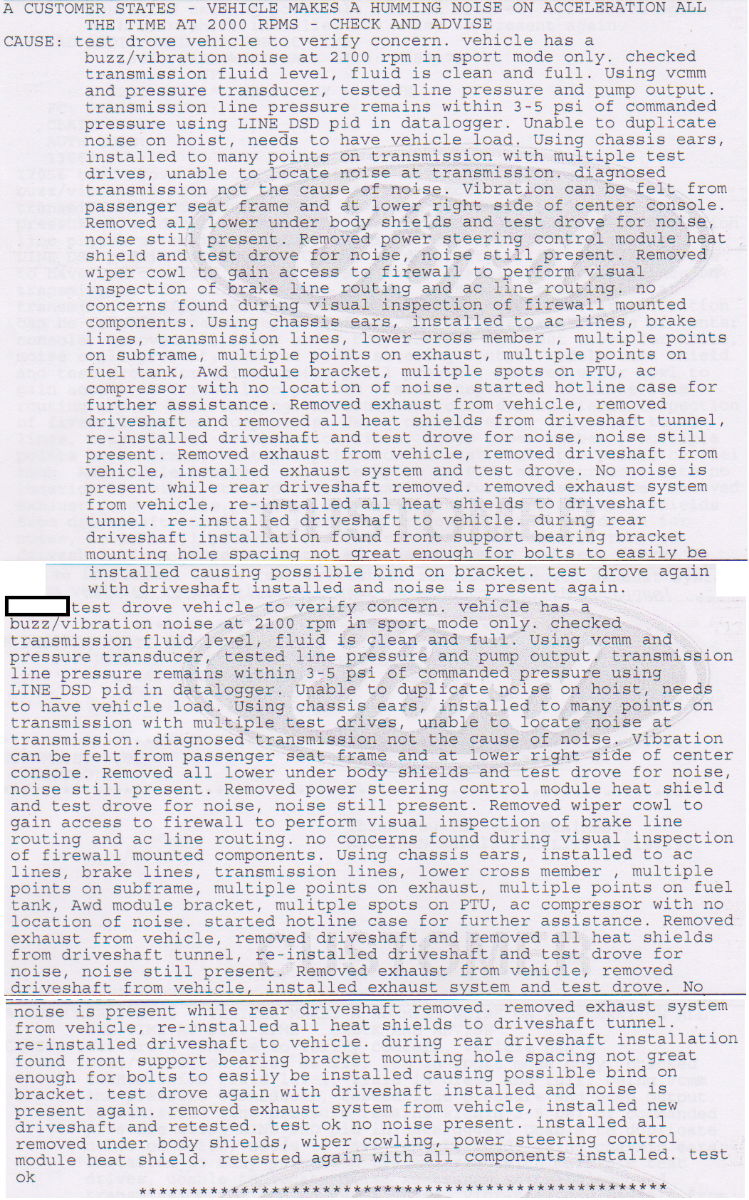
Back again after a different dealership having my Edge for just about a month. I THINK we have figured out the problem. I will paste the (quite long) write-up from the master mechanic - as it would be more helpful than anything I would try to explain. Hopefully it helps at least ONE person that may be experiencing a similar problem. 2020 Ford Edge ST with 17k miles on it, 100 visits to dealerships, ridiculous amounts of time without the car, $1000's wasted, "fixes" that ended up not being fixes, etc. The master mechanic found it to be the driveshaft installed improperly from the factory. Please read the write-up for more details. I appreciate all the messages with guesses at what this could be. After getting a new transmission and it essentially being a placebo-fix where we weren't hearing the noise for a short period, here is to hoping that this new, properly installed driveshaft resolves this FIVE YEAR problem we've been experiencing. Thanks again!
 4 points
 -
It was her sisters, who died unexpectedly. So mostly a sentiment hesitancy.3 points
-
It's your money so spend it any way you wish, however . . . The BOV will gain you that whoosh noise you want, but that's all. If you are looking for 400 / 420, then an Unleashed Tune will get you there. Average numbers are gains of 60 HP / 70 TQ. I have no idea what the Livernois tune got you as you have not said. An FMIC is a good addition as it will help keep a cooler charge, not more power. High flow CATS? If you think those are going to get you big power gains, they won't. But, they could change your exhaust noise, given a larger exhaust. Bigger turbos? You won't need those either to reach your stated goals ( 400 AWD HP and 420 AWD TQ )3 points
-
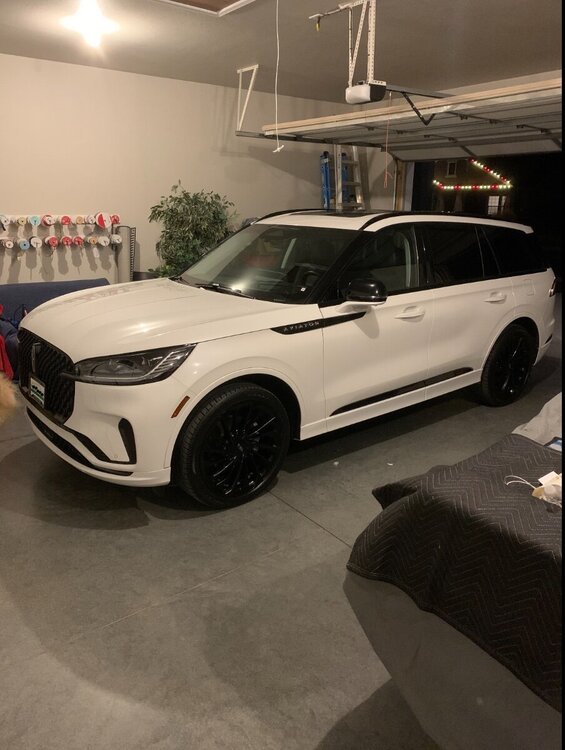
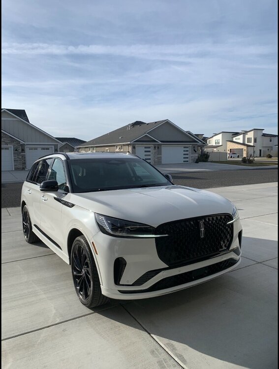
Even though I never put a wrench to my Edge, except for maintenance, It’s been nice using this forum to learn a lot about it. I just had an itch to upgrade my car. I hope it’s as reliable as the Edge as there are lots gadgets on this thing. I now have a 2025 Lincoln Aviator reserve 2.
 3 points
 -
I have Forscan, but opted for the aftermarket disable switch instead. Works perfectly. I wish I could remember what it's called and where I got it but it's a three to five min install w/zero hassle. I Googled it. Like my better half, Google knows Everything!3 points
-
On June 20, 2025, Ford provided the following information to dealership Service personnel via an Alert issued on the Professional Technician System (PTS) website... Some 2021-2024 Ford and Lincoln vehicles equipped with SYNC 4 may not be able to perform an update to the accessory protocol interface module (APIM). This may be due to the software in the APIM. Ford Engineering has de-activated the ability to update these SYNC 4 APIM modules and as applicable, the Ford Diagnosis and Repair System (FDRS) will not present an update for the APIM module. Some existing directed repairs may be impacted, check OASIS before attempting any specific TSB repairs and landing pages before attempting any specific FSA repairs. For any vehicles repairs requiring a software update that includes an APIM update in the programming sequence, if the 5-digit product code for the APIM software is equal to or lower than 23187, do not attempt to update affected modules at this time. To determine the 5-digit product code for the APIM software on the vehicle, while the vehicle center display screen is powered up with ignition in run or accessory, go to General Settings > Select About SYNC. Find the 5-digit code, example “ SYNC 4, Software Version: 23187_PRODUCT”. This post will be updated when Ford offers fuller clarity, or, when a remedy is provided by Ford Engineering.3 points
-
I don't think they are " one-time use " either but Ford is being cautious. It's like saying, on older cars, every time you change the oil you have to change the oil drain plug gasket. Not a true statement. It's very tight in there to remove that PTU cover plate without moving anything else. I chose to buy a MityVac unit specifically for vacuuming out the gear fluid. Sucked it almost dry. I used another MityVac unit, so I didn't have to clean them in-between same-time uses for the PTU, to pump the new gear oil in. Took the correct amount of fluid as specified in the manuals. ( That's why I said it sucked it dry ) And, of course, a lot less messier.3 points
-
Found this 2013 Edge sel 2.0 ecoboost and had to have it.. So far it's been good to me.

 3 points
 -
I confirmed with Bellevue Ford tech that their service manual says the same about adding 1L once full to the 2019+ ST.3 points
-
Well, I've done something rash. Traded my 2019 Flex NA AWD for a 2024 Edge ST. The Flex had 105K on the clock and I wanted a vehicle with a official Ford tow package for the small trailer I'll be pulling. Local Ford store had one I liked, so I got it. Has a few more miles than I'd like (39K), but I might just run it for a couple years and switch to an Explorer ST (unless you all talk me out of it...). It is fun to drive and in regular driving is getting better mileage that the Flex. We'll see how it tows the trailer, as I leave Wednesday for the trip. The Flex had tons of room when you laid down the second row seats, so I'm gonna miss that, but the trailer lets me put some stuff that used to go in the car now into the trailer. It's just a 5X8 trailer holding my Honda ATV. So all told maybe 1200lbs. The items I put in the back of the car for the trip should just fit. I need 67" and the Edge has 70". Tuesday is loading day. Sorry I don't have a pic of the car yet. But it's a very dark Blue. Don't know the official color name... The B&O sound system is kinda cool. Pic attached to show what has to fit in the back... it comes apart, but the longest piece is 67" long. sidebar: why did it put the pic sideways, and how do I correct it?🤔
 3 points
 -
Looking at that new drain plug I see that it allows a more controlled drain flow - you can partially turn it out until there's flow from the port while the threads are still engaged. Getting the small O-ring on the tip of the filter housing I take off the gloves and make sure everything is dry then push it down and over. .3 points
-
Just an update on the Disconnect RDU gear oil: Ford Recommended Gear Oil = Motorcraft Rear Axle Oil - XY75WQL at a mere $32.99 on Amazon. I just got off the phone with Redline Technical Service. According to Redline, their corresponding oil will be Red Line 50604 MT-LV 70W/75W GL-4 High-Performance Full Synthetic Gear Oil Lubricant for Manual Transmissions & Transaxles - 1 Quart. for $22 on Amazon Nothing apparently available from Motul. Just an FYI for those interested. Also Note: While it's true as stated by someone earlier, Ford can't deny you ( allegedly ) any claim if you use Ford Recommended products. However, in reality, the manufacturer can't deny a claim as long as you use the appropriate grade product, IE; if you use a comparable 5W-30 motor oil other than Ford product, all else being equal, they can't deny you. Just remember to use quality products, not some cheap version from Walmart, etc.3 points
-
UPDATE: Late last week, the dealership diagnosed it as a bad transfer case. I’m hoping this fixes the issue but we shall see. 🤞🏼3 points
-
Ford has disabled software updates for the computer in your infotainment system called the APIM (Accessory Protocol Interface Module). This is basically the computer that runs your SYNC 4 system (your touch screen, navigation, apps, etc.). If your vehicle's SYNC 4 software version is 23187 or older, your vehicle's infotainment system cannot currently be updated, not even by a Ford dealership. Ford made a technical decision to block updates for certain SYNC 4 systems. As of now, they haven’t explained why. Ford is expected to release more info or a fix later.3 points
-
*** The following Dealer Bulletin has been edited to provide the information most relevant to Forum members. ***

 3 points
 -
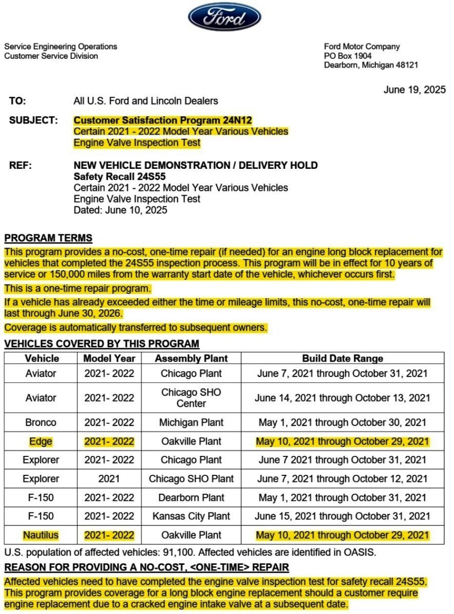
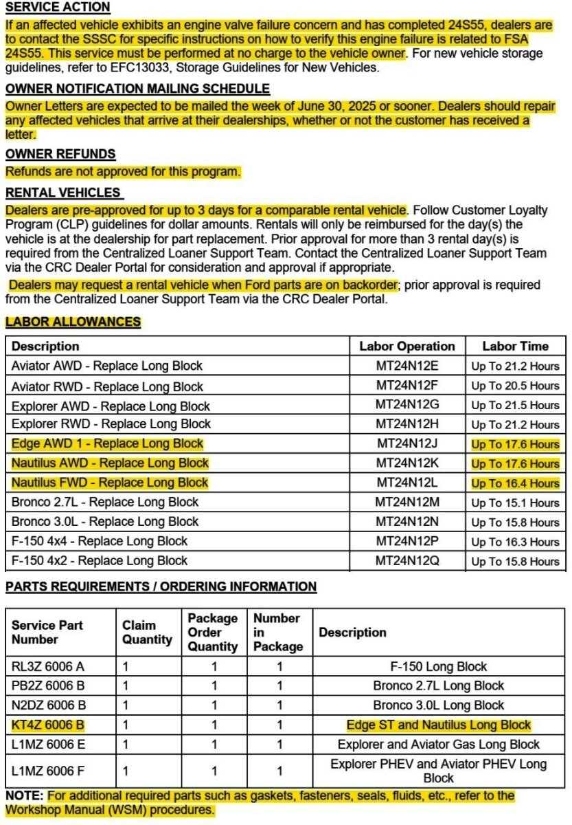
From the above-quoted NHTSA Chronology Report, with emphasis added... On January 25, 2022, Global CCRG opened an investigation into 2021 Model Year (MY) Lincoln Aviator and Nautilus vehicles equipped with 2.7L and 3.0L Nano EcoBoost gasoline engines after an international investigation discovered twenty-two (22) instances of engine failure at three (3) months in service or less. A review of failed engines revealed that the engine intake valves fractured and fell into the combustion chamber of the engine causing catastrophic engine damage leading to a Loss of Motive Power (LOMP). Based on an analysis of returned fractured valves from failed engines, Ford identified that the potential root cause of the failures was engine intake valve failure due to valves that exceeded the designed specification for hardness, were brittle, and more likely to fracture. Ford determined that this was due to the supplier’s grinding processes and the sensitivity of the intake valve material to grinding processes that were not within control specifications. The intake valve material was changed for vehicles produced after October 31, 2021. The new material increased the valve’s robustness to keeper groove grinding processes outside of control specifications. Good luck!3 points
-
Sounds dramatic doesn't it.! In my over 60 years of owning vehicles, including 5 or 6 Ford products, I have learned many things....especially about FORD products. I've loved everyone I've owned, mostly for their drive-ability. I like the handling, the performance, style, and comfort of all of them. I've owned two Edges. The most recent was a 2019 SEL. My first, in a very long time, 4 banger. I think that the Turbo made all the difference. I enjoyed driving that car. I decided that since my age was getting up there, I would really maintain that car. I was very motivated to keep it a long time. Much so that I had the transmission fluid changed at 89,000 miles. That was a $500 maintenance item. Also a new battery about a year ago. Lastly, new tires six months ago. Here is where the story changes...at least for me (us). In the past, I've had issues with one Ford over Wheel Bearings. Seemed to be the rage back then. I believe it was an Explorer. Then was the Expedition. LOVED that vehicle. But it seemed to always have an issue. Not huge, just some little thing going wrong. Then one of my first Edges. That one was actually relatively trouble free. Just the 'normal' things happening. Now, this last one. The one that I just traded. The one where I put new tires, battery, and TRANSMISSION into. Yup, the one that I kept serviced to the 9s! At 89,000 miles the transmission went out!! The mighty 8 speed transmission, kaput!. $7000 to replace it! Fortunately, I had bought an extended warranty from ROUTE 66, through my credit union. I say fortunately, because when I bought the car at my "LOCAL" Ford dealer, they offered my any one of three extended warranties. FORD, CHRYSLER, AND ZURICK. All of these were just too expensive. So, when it came time for the transmission issue, I went back to my purchasing dealer. THEY REFUSED(at first), TO TAKE THE ROUTE66 policy. They eventually agreed to take it, but it was TO LATE!! I took it to another dealer who had no trouble taking the Route66 warranty! So, after buying something like 5 vehicles, in 20 years, at the "local" dealer, our relationship ended! I was also pissed that the vehicle that I maintained so well, was starting to nickle and dime me to death!! The transmission was just not acting right (the replacement did have a 3yr, unlimited mileage warranty). I just did not want to deal with it anymore. Also, the windshield washer decided to act wounded. I researched how to change it out ($70), or have it done, ($180hr plus the part). Research showed me that the inner fender had to be removed for access!. Then the rear power hatch or door or whatever it's called, would every so often get a mind of it's own. I probably was looking at it wrong but it just was thinking of becoming a problem. All this was very frustrating......BUT, the real kicker........Whenever we went to our local Hardee's for breakfast, I had to back on the far side of the parking lot!! Yup, something would affect the wireless gremlins inside the critter so that the Keyless entry system would not work. I could not lock or unlock the car, nor, on several occasions would it start. Frustrating...for sure. The dealer's input, it's Hardee's drive through WIRELESS system that was messing up my Edge. Part further away! ( me with two bad knees and a handicap plate!) In conclusion.....I got rid of that Ford Edge! After 80 years, I bought my FIRST FOREIGN car. A SUBARU FORRESTER. I have remained pretty much in the background in these forums. Occasionally posting but mostly watching and learning for many of YOU. THANK YOU, ALL OF YOU. ADIOS!!
 3 points
 -
You should pop off the cover like it says and check. My 2019 SEL has 5 pin wiring to the rear view mirror, I was able to find the male and female connectors and pins to make my own harness to get switched 12v from the rear view mirror. I wasn't willing to spend $42 on a Dongar adapter, or $150 like the one you posted.3 points
-
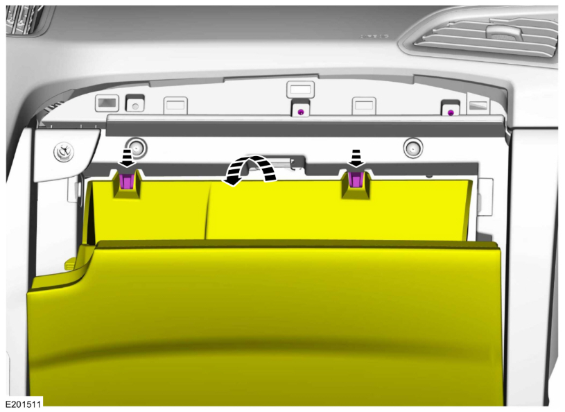
Welcome to the Forum @Milo M! To ensure your personal Health and Safety, because the Passenger Knee Bag is integral to the Glove Box assembly, please review and fulfill the Supplemental Restraint System depowering and repowering procedures... From the 2019 Edge Workshop Manual... WARNING: The following procedure prescribes critical repair steps required for correct restraint system operation during a crash. Follow all notes and steps carefully. Failure to follow step instructions may result in incorrect operation of the restraint system and increases the risk of serious personal injury or death in a crash. NOTE: Removal steps in this procedure may contain installation details. Depower the SRS . Refer to: Supplemental Restraint System (SRS) Depowering (501-20B Supplemental Restraint System, General Procedures)... (This procedure is also attached below as a PDF document) Removal Open the glove compartment. Detach the glove compartment door damper. Push the tabs and release the glove compartment door. 4 Disconnect the electrical connectors. Remove the bolts. Torque: 35 lb.in (4 Nm) Remove the screws. Torque: 22 lb.in (2.5 Nm) Release the clips and remove the glove compartment. Use the General Equipment: Interior Trim Remover (This procedure is also attached below as a PDF document) Good luck, and Work Safely! Supplemental Restraint System (SRS) Depowering - General Procedures - 2019 Edge Workshop Manual.pdf Supplemental Restraint System (SRS) Repowering - General Procedures - 2019 Edge Workshop Manual.pdf
Repowering-GeneralProcedures-2019EdgeWorkshopManual.thumb.jpg.9f065584f1c6f7e91e11ee548f927a78.jpg)
Depowering-GeneralProcedures-2019EdgeWorkshopManual.thumb.jpg.d3c4a5d95affb20f562f0beac109900e.jpg) 3 points
3 points -
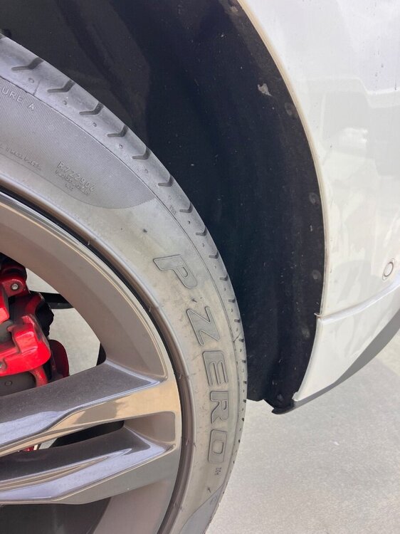
Additional documents... Good luck! Ride Height Measurement - General Procedures - 2017 Edge Workshop Manual.pdf Wheels and Tires - Diagnosis and Testing - 2017 Edge Workshop Manual.pdf PINPOINT TEST A - INNER EDGE, SHOULDER WEAR - Diagnosis and Testing - 2017 Edge Workshop Manual.pdf3 points
-
Rafeek, I just noticed the same thing on my new 2024 Edge ST. and I too have temporarily secured it with cable ties. My St does have the tow package and could you give me any additional information on where to get this part. Thanks so much3 points
-
Somewhat ironically, the Suspension System Specifications page is identical in both the 2017 Edge and 2016 Edge Workshop Manuals, with each bearing the 2016 model year Edge reference in its upper right corner, as shown on the below-attached PDF page... Good luck! 2016 Edge + 2017 Edge Workshop Manuals - Suspension System Specifications.pdf3 points
-
That was it. Something wasn’t programmed right. Now, all 12 of my parking sensors are beeping and working correctly.3 points
-
Got around to installing the SP-542 (.028 gap). Interesting the OEM plugs on my 2019 that I removed are in fact SP578 CYFS12YPT. They didn't look great at 45K miles. Idles and drives maybe a little smoother. A few notes from the install - As simple as it was a screwdriver popped the plastic clips off Ford's favorite 8mm nut stud. Otherwise they were not fun. Before the intercooler pipe can be moved, the blow off valve/diverter valve dump tube needs to be removed. It's a PITD. I used a spray bottle with some really really hot soapy water and it came off a lot easier. Once you get the intercooler pipe / air cleaner outlet pipe moved left (passenger) of the wiring harness it becomes more easily moveable. Once the pipe is to the left of the wiring harness, it makes sense to secure it with something (zip-tie, wire, tie-down, shoe-lace, or even duct tape like I had within reach). Now there's plenty of clearance for that coil. Was able to fit my CDI (1501MRMH) 1/4 torque wrench on every plug. 133 in-lbs / 15 Nm / 11 ft-lb3 points
-
The last update I received on my 21MY Ford was Software Update 6.4.0 in February. I think the 21MY vehicles get updates last or whenever Ford feels like it. I don't know if you check other forums on vehicles with SYNC4 but it does seem like the 21s are last to be updated. Not much we can do stressing about updates, whenever we are blessed by Ford is when we will get updates3 points
-
Representative sections from the 2014 Edge Workshop Manual and Wiring Resource are attached below as PDF documents... Good luck! Liftgate Trim Panel - Removal and Installation - 2014 Edge Workshop Manual.pdf Liftgate Release Switch - Removal and Installation - 2014 Edge Workshop Manual.pdf LIFTGATE RELEASE SWITCH - Connector C4216 Pinout Diagram - 2014 Edge.pdf LIFTGATE RELEASE SWITCH - Connector C4216 Location - 2014 Edge.pdf3 points
-
Thank you for the quick response! I purused @Wubster100 post and will try some of the things they did. Also found a post by @Remis that appears to be having same problem - @Haz posted a comprehensive response. I think I'll brew a pot of coffee and work through the posts.3 points
-
I might get this wrong with what was explained, but we were told that the incorrect install from factory with the bracket and the driveshaft caused for the driveshaft to contort a little bit due to misaligning the bolts. The bolts were able to fit perfectly into place with the bracket on the new driveshaft. I apologize for my ignorance as this is like a different language for me.3 points


Repowering-GeneralProcedures-2019EdgeWorkshopManual.jpg.9f10907fda73551e97ea8dc5d2b7bc33.jpg)
Depowering-GeneralProcedures-2019EdgeWorkshopManual.jpg.04864bd831dad91e97de94d0c707fd8a.jpg)