Leaderboard


Popular Content
Showing content with the highest reputation since 03/05/2026 in all areas
-
Of course you can BUT . . .. Adding new fluid to " top off " the old fluid does extend the use of the old fluid to some amount, but does not equal actually replacing the old fluid with fresh fluid What do you do when the fluid level of the PTU is FULL and you can't add any new gear oil? Unless you have evidence that the PTU is leaking, there is no need to add fluid. If the PTU fluid has been in there at least 20K miles, then you need to change it out completely. Forget the fact the manual says the PTU fluid is good for 30K miles. Go with that if you wish but at 20K miles, mine was a dirty, dark brown fluid. You have to remember that the PTU is sandwiched between the transmission, engine and exhaust systems. That is a pretty hostile environment, adding to the fact the amount of PTU fluid is small. And, there is no need to pull the PTU to drain the old fluid. You can literally use a vacuum unit designed for fluid removal to vacuum ( suck ) all the PTU fluid out and then pump all new fluid into the PTU for the refill. That is what I did and it works easily with zero mess.3 points
-
It was her sisters, who died unexpectedly. So mostly a sentiment hesitancy.3 points
-
Hi guys! Hello, I would like to share my observations about the anti-corrosion protection of our Ford Edge cars. Or more precisely - about the factory lack of this protection. My ST just turned 4 years old. The car is very nice, I like it, there will be no newer generations, Ford doesn't give a damn about cool projects, because what's more important to them is 'diversity BS' and battery-powered Mustangs (hahahah). So, when my ST was 3 years and 9 months old, I decided to give it a proper chassis maintenance. At the beginning, it was supposed to be a thorough cleaning and basic protection (wax for closed profiles, polyutherane for visible surfaces). After washing and drying the chassis and dismantling the covers, it turned out that the Ford Motor Company had practically neglected the topic of anti-corrosion protection! This is a scandal. The joints of the sheet metal elements of the bodywork are not protected against the ingress of water and oxygen - a real invitation to corrosion! There could only be one decision: dismantling the covers, covers, rear suspension, drive, diff, shaft, exhaust, tank. Then comprehensive sandblasting of the entire chassis, application of polyurethane primer, mastic to protect the joints of sheet metal, and then rubber on the chassis and in the wheel arches. Top with hot injected waxes. At the same time, the elements of the rear suspension and the tow hook were sandblasted (rubber elements, threads, etc. protected) and covered with a special varnish. Top it all with a layer of wax. The car was in the service center for 2 months (I wasn't in a hurry). The effect is fantastic and I'm glad I decided to protect this nice car. My main message here is: shame! Shame on FoMoCo for such a scandalous approach to such an important topic as anti-corrosion protection. I can't call it anything other than intentional aging of the product. Take care of your lovely STs! I'd like to share with you a video report i was given from the guys that were doing all this work. It's in Polish - pls, use YT auto translation - it's working quite nicely. Cheers.3 points
-
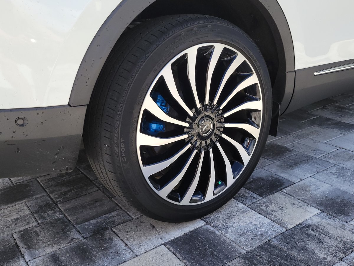
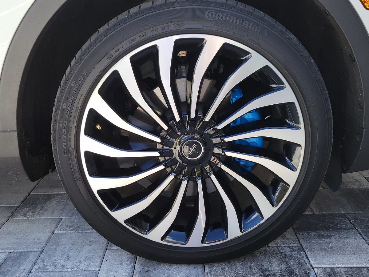
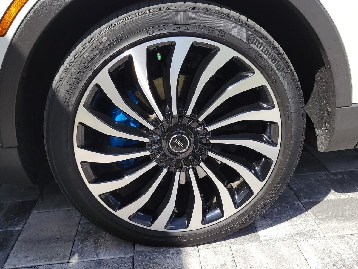
Great to hear 1004ron ! I'm just happy I don't have to remove the wheels in the near future to install new pads. Those 21's are hea-VY. Here are a few pics of the brake calipers, as promised. Can't see them very well, but, they look a little better when the sun is not directly overhead and casting shadows.


 3 points
 -
Thank you. I've tried another reset (after trying at least three different instructions that didn't work). Pressing Power, Defrost (front), and Off at the same time resulted in horizontal segments at the beginning and two 88s displayed at the temperature values at the end, supposedly meaning a successful reset with no error codes. We'll see.2 points
-
You do not need access to OASIS to find any recalls or TSBs related to your vehicle. A simple internet search for 2020 Ford Edge ST TSBs and safety recalls will provide you with that list. As to which TSBs / safety recalls have been performed on your particular vehicle, you may not be able to get that answer simply because if they were performed, the dealer most likely never documented them. That was my personal experience when I checked these for my car and discussed them with my former dealer.. TIP: If you compile a complete list of TSBs / safety recalls on your car, and you take that list to your dealer, don't be surprised if you piss them off. According to my former Ford dealer, they do not have to perform any TSBs UNLESS your car is actively having an issue related to a specific TSB. Safety recalls are different and they have to perform safety recalls. As far as the 2020 Ford Edge ST, I have found zero safety recalls that affect my car. I just noticed you are in Poland. Maybe you have better dealers there than in the U.S.2 points
-
● You check your tire pressure. ● You check your transmission fluid level. ● You check your coolant level. ● You check your power steering fluid level. ● You check your brake fluid level. ● You check your oil level. ● You check your engine air filter. ● You check your cabin filter. ● You check your seat filter. ● You check your exterior. lights to verify everything's working. ...... What are you forgetting? ....... What's the one thing you should be checking but haven't since .... ???? •• Tire pressure of the spare tire, hidden away in the trunk. 🚗....2 points
-
Well my question would be, why do you still have it? It seems like it's been nothing but trouble and a money pit. Is there any reason you are keeping it?2 points
-
Just got updated as well new Updated SYNC to build 25213 Revision 19812 points
-
Sync updated today. Module updated was APIM 25.2.0.16.12 points
-
Winters are very weak those years. The most recent one was quite normal - as winter should be. Plenty of snow. Yes, they are using salt on the roads but this tendency, as far as i know, is declining heavily. Snow/no snow, salt/no salt is one thing. Zero anti-corrosion protection as per design - is the second thing. After all corrosion is not only about salt. It is happening 24/7.2 points
-
That is a major undertaking and must cost a fortune in labor and materials but will serve you well for many years.2 points
-
I took it to a mechanic who replaced two fuses (which I could not reach myself) and that fixed the interior lighting problem. Thanks for the help.1 point
-
Sorry to hear about the family loss that led to your ownership of the Edge. I don't have any specific fault finding to suggest but have not seen the lack of cabin heating reported here, which leads me to believe that there's a solution to your problem, just need to identify what that is.1 point
-
Yes, I am able to.1 point
-
Hi everyone, I’m looking for some help from anyone with OASIS access to pull a report for my Edge ST. I’m trying to verify the vehicle's service history (repairs/replacements) and check for any outstanding recalls or TSBs. I am particularly interested in any updates regarding the TCM (Transmission Control Module) or PCM. (shit 2>3 problem) Vehicle Data (from FORScan): VIN: 2FMPK4AP8LBA92260 Model: 2020 Ford Edge ST Engine: 2.7L EcoBoost V6 Current PCM Strategy: K2GA-14C204-GFE PCM Calibration Level: K2GA-12A650-GFE Mileage: ~91,200 km (approx. 56,700 miles) I would greatly appreciate it if someone could provide a printout or a summary of what’s in the system. If there’s a small fee for your time/trouble, please let me know via PM. Thanks in advance for the help!1 point
-
I'd have to go back and check, but I recall the TSB's aren't mandatory whereas the safety recalls are. NHTSA vehicle safety recalls are mandatory, not voluntary, if a defect poses an unreasonable safety risk or fails to meet federal standards Check for Recalls: Vehicle, Car Seat, Tire, Equipment | NHTSA1 point
-
Why not just re-paint it gloss black?1 point
-
I don't use a torque wrench on the lug nuts, so can't comment on that question. Within the first 15K miles of my Sports life the Ford dealership damaged the aluminum cladding on the lug nuts due to the use of impact wrenches for removing and installing them - they gave me a complete new set - 125K miles and they're still in "as new" condition. Recently had tires installed at Costco - added clear instructions to the job card that no impact wrench be used - I watched and they didn't use impacts. .1 point
-
Software Update Notes for my 2021 Ford Edge SE This is the most comprehensive update list I have seen for the 2021 model year Edge. I do not know if other years follow the same update patterns as the 2021 model year. I am missing the release notes for Power up 1.6.X or 1.7.X which ever my vehicle installed right after purchase from the dealership. My vehicle is also registered in the Early Access Program. Ford has a link to see what updates your vehicle has done (seems to only show updates since the start of 2025). https://www.ford.com/support/software-update-release-notes-history/ Ford Power-Up 2.3.1 Ford Assistant Ever wanted to talk to your vehicle? Well, now you can with your own Ford Assistant. Just say, "OK, Ford" to wake up your assistant and ask questions like "How does my Cruise Control work?" Your rear view camera system has an update to resolve any blank screens or distorted images. Completion of this update resolves the safety recall 22S14, and no further action is required. Ongoing updates like this help you enjoy the best possible version of your Edge ® SUV. Keep in mind that feature availability varies by model. For more information on these features, visit Ford.com/support or your digital Owner's Manual. Ford Power-Up 2.3.2 Ford Assistant Note that you may have received some of this functionality in a previous version, but this update has been enhanced. Ever wanted to talk to your vehicle? Well, now you can with your own Ford Assistant. Just say, "OK, Ford" to wake up your assistant and ask questions like "How does my Cruise Control work?" Your rear view camera system has an update to resolve any blank screens or distorted images. Completion of this update resolves the safety recall 22S14, and no further action is required. Ongoing updates like this help you enjoy the best possible version of your Edge ® SUV. Keep in mind that feature availability varies by model. For more information on these features, visit Ford.com/support or your digital Owner's Manual. Ford Power-Up 3.5.2 Big things are coming. Alexa Built-in, the road-going version of Amazon's ever-helpful assistant, is coming to your vehicle soon. This update helps prepare your vehicle for Alexa Built-in and other future improvements. Stay tuned because another download will arrive soon to complete the process. Because of its complexity, this update may take longer than usual. But we promise you, it will be worth it. Ongoing updates like this help you enjoy the best possible version of your Edge® SUV. Ford Power-Up 3.5.3 We've been super busy. Check these out. Alexa Built-in Yes, it's almost here. Most of Alexa Built-in has now been downloaded, with the final piece arriving in a few more days. Then you can wake Alexa up. Make a call, check the weather, interact with your smart-home devices, make a shopping list, ask for a joke. Just about anything you use Alexa for at home, you'll be able to do in your vehicle. Plus, add Ford Streaming and listen to music and podcasts too. You'll know it's time to activate Alexa when the icon appears on your SYNC® 4 Technology screen. Just click on it and follow the steps to register. Keep in mind that your vehicle must have Enhanced Voice Recognition and an activated modem. And, of course, you'll need an Amazon account. More good news: Your first three years of Alexa access are on Us (streaming media services not included). That three-year clock starts ticking the moment the Alexa icon appears, so don't wait to set it up. You're gonna love it. Go to your Ford Account or FordPass® App to learn even more. Ford Power-Up 3.5.4 You may have noticed we've recently made some more updates. Advanced Dual Phone Access two phones at the same time without having to mess with the settings. You could, for example, easily access both phones for incoming calls, contacts, text messages, emails and more. Digital Owner's Manual We made sure what you need to know is in there and easy to find. Go see it at Ford.com/ support, in-vehicle or in the FordPass® App. Ongoing updates like this help you enjoy the best possible version of your Edge® SUV. Ford Power-Up 4.2.1 Here's the Latest Just for You We've made improvements to the software update process, including the ability to enter your vehicle using your Key Fob during a non-drivable update. You'll also now receive new pop-up alerts to inform you when a precondition is not being met so that you can take the required action to receive your update. For a non-drivable update, preconditions may include that your vehicle is parked, it's not running, all the lights are off, doors and trunk are closed, and you're not pressing the brake pedal. Ford Power-Up delivers software updates that are designed to make your Edge® SUV better over time. Ford Power-Up 4.2.2 We've been busy. Take a look at what we've done. SYNC® 4A With Even More Wow You may have noticed that things look a little different on your vehicle's SYNC screen today. That's because we just unveiled a new, modern design that will make it simple to find your favorite settings and controls, create your personal profile, access Ford Power-Up Software Update details and But wait, there's even more: Home Screen - Simple refinements to help improve navigation Status Bar — New icons to help you find your favorite features quickly Settings and Controls — Consolidated so you can easily access drive modes and Software Update details Personal Profile — Personalize your in-vehicle experience with a personal profile, now easily accessible from the status Software Updates — In-vehicle scheduling is easy now that you can choose preselected days and times based on our recommendations or pick your own to create a custom schedule to better fit your lifestyle Ford Power-Up delivers software updates that are designed to help make your Ford Edge® SUV better over time. Feature availability varies by model. Ford Power-Up 4.2.3 Convenience of Wi-Fi From Virtually Wherever This Ford Power-Up software update allows you to connect to public Wi-Fi hotspots through SYNC®. So, whether you're sitting in a restaurant's parking lot enjoying a lunch break, outside of a retail store or a coffee shop, you will be able to connect to public Wi-Fi through your SYNC ® screen. Then it's just a matter of being redirected to accept any terms and conditions and voilà - you're online. Take advantage of this feature so you can download software updates faster, get seamless access to popular news and entertainment platforms and more, right on your in-vehicle screen. So surf away and enjoy. Ford Power-Up delivers Software Updates that are designed to help make your Ford Edger SUV better over time. January 2025 ECG-24.2.4.10.1 This update improves the way your vehicle receives and transmits software resulting in a more dependable update experience. Mode Software updates are designed to help make your vehicle better over time. January 2025 Software Update 6.2.0 Connectivity Upgrade . Your vehicle's modem has been enhanced, providing you with amore seamless interaction with network services to help keep you connected on the go. Software updates are designed to help make your vehicle better over time. February 2025 Software Update 6.4.0 Improved Vehicle Health Monitoring • We’ve enabled new features for monitoring your vehicle’s wheel alignment, wheel vibration, and battery health, providing better diagnostics and enhancing your overall driving experience. July 2025 Software Update 6.14.0 SYNC Updates • While your center display is receiving the latest software update, you may see the message "Some display features may be temporarily unavailable." • This is normal and part of a brief process that helps bring the latest system improvements to your vehicle. • After the update, your vehicle will notify you while SYNC is updating. Step up to the mic, please For this latest Ford Power-Up software update, we listened to your feedback and made it easier for you to continue to share your experiences by recording and sending voice feedback from the convenience of your vehicle. Prior to this update., access for this feature was in the Settings-General menu. But now it's been moved to the App screen and will be available whenever your vehicle is activated in FordPass@. Look for the new Record Feedback microphone icon- and continue to let us know what you really think. Available in the U.S. only. Software updates are designed to help make your vehicle better over time. March 2026- SYNC-25.2.0.16.1 SiriusXM Improvements This software update contains the following key changes: • We’ve made some disk space enhancements to ensure optimal performance of your vehicle’s SiriusXM service.1 point
-
The dealer does not do body work (as I suspected) but he gave me the address of a body shop they use as needed. I will go to this shop next week some time and post back. Body shops are "tricky" business so I would rather go to one it's recommended by the dealer. My thanks to all1 point
-
Is there any hack or alternative software to install that I can change the layout of the touch screen? I hate the current layout. For example, see the attached. When I want to go into climate, my eyes and finger must travel a LOOOOONG distance on that display and that is terrible in of itself, its also distracting and dangerous. 1. say I want to turn off the climate system. Finger presses Button on bottom, finger to top off button, finger back to bottom to close the screen. Ridicoulous 2. say I want to recirculate the air. Finger presses Button on bottom, finger to top circulations button, finger back to bottom to close the screen. Ridicoulous UGH! I have no clue who allowed this navigation nightmare in the first place, but it sucks. Plain and simple. So now, in all todays day and age, is there a hack to this software where I can override and change the layout to my liking?
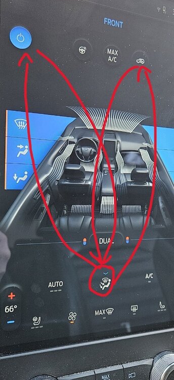 1 point
 -
You can change the temperature and fan speed with the steering wheel switch1 point
-
What is IPC climate control?1 point
-
I got it working. I also had to change 726-45-01 to xxx-x3xx-xxx. I ended up using power from the 12 volt outlet in the car. The cupholder lights come on when the headlights come on. However, they say on if you then turn the headlights off until you shut off the car. I also can't dim them or turn them off using the sync screen. Can you control your cupholder lights from the screen?1 point
-
Any luck finding the changes. I got it on the screen by changing the apim. Just not sure of the changes to make in forscan for the bcm.1 point
-
Your account is active.1 point
-
You do not need to remove the BCM or solder anything. Instead, to add a wire, you unplug the connector from the BCM, then you can take apart the connector, and push a new pin into it. You can access the BCM by reaching up under the dash, and you can remove the small cover in the front that is right below the headlamp switch. Program with FORScan. Changes in BCM to enable rear fog lights. And IPC to enable the indicator.1 point
-
bloody internet... Possible to put them here as a photos, not links to external websites?
 1 point
 -
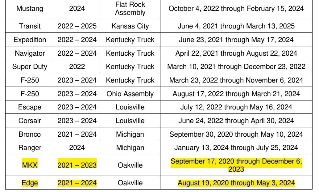
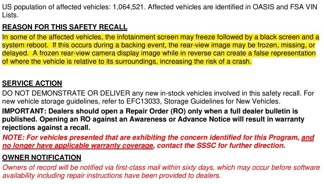
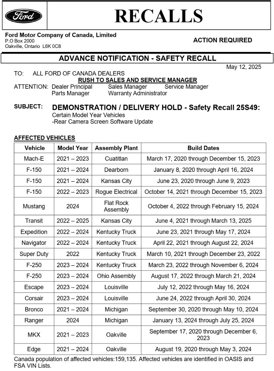
*** This is an Advance Notice -- This post will be updated when the Full Dealer Bulletin is released *** Please note: The Advance Notice letter contains a typo, indicating "MKX" for model years that clearly represent the Nautilus model...
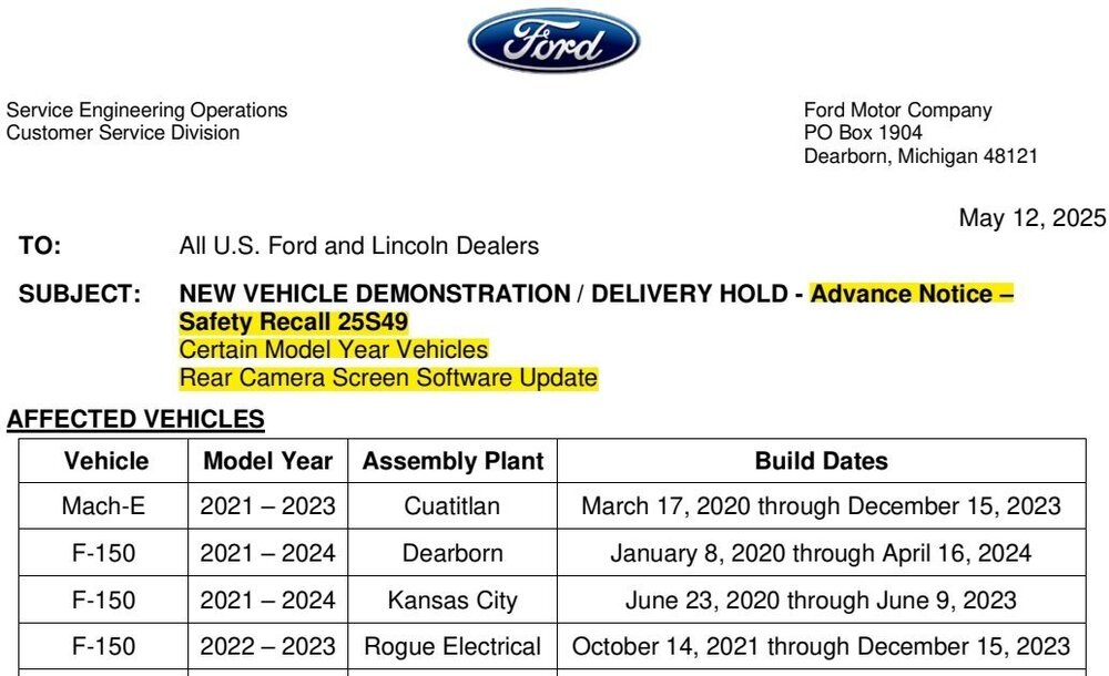
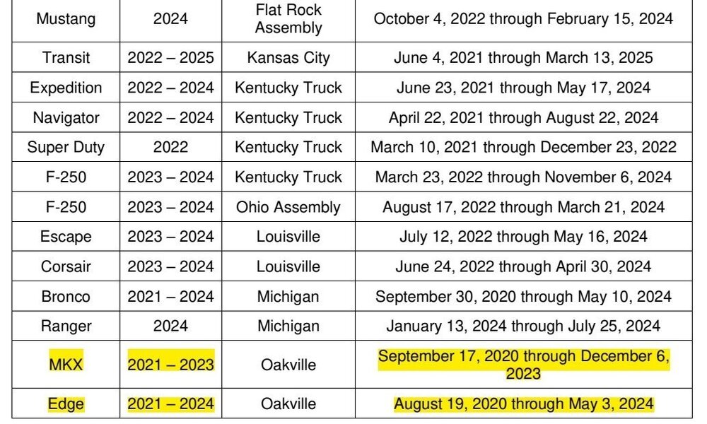

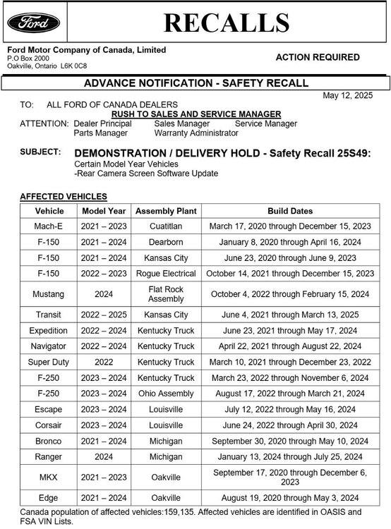 1 point
 -
I have not had any issue yet in my 2016 Edge, or my 2023 Explorer, but when I had my 2019 SuperDuty, I had to replace the front camera. The rear was fine before I traded it in, so I don't know if it ever failed or not. It was under recall, but when I traded it, it was still "awaiting parts". I bought the front camera from an online Ford dealer for a great price, and changed it myself. Took about an hour and all was well. My Edge is under recall for the camera, (guess what...parts unavailable at this time".) The Explorer has no recalls at the moment.1 point
-
I know. It just doesn't make sense. How in the world could Ford be so careless. What are they doing wrong? No wonder everyone is buying the competition. I get it, with all the technology packed into today's vehicles, there will be issues. But Ford is screwing up big time. My ST has not had this issue. But there have been plenty of other small issues that make me wonder??? Did I buy a piece of Junk????1 point
-
Man, these rear-view camera issues have been going on for years. Why can't Ford get it right? You'd figure after this long, they would have it figured out.1 point
-
I made the change in the apim to a 2 from a 3 thinking that would enable the menu in sync but it didn’t. I haven’t installed the cup holders or ran the Lin wire from the bcm yet because I want to make sure I can get the menu to show up first. Can I get the menu on sync by changing the apim before the cup holders or wire from bcm is installed or does everything need to be installed to get the menu to display.1 point
-
I have a 2024 which has sync 4. Do you remember the changes you made with forscan to the bcm and apim?1 point
-
Since we all three have the GEN 1 engine, I have to ask. Any major issues with the drivetrain ... as relates to your modifications or high milage? Already doing the fluid/oil changes and frequent maintenance. Also using CRC Turbo & Injector cleaner and considering the TechTron fuel additive in hopes of keeping the fuel system free of carbon buildup in the engine and moisture out of the tank. Hope y'all are having a good weekend. Always open to suggestions.1 point
-
If you disconnect the battery before removing the seat and reconnect it after returning the seat, then the Airbag light will not come on. If you have ForScan, you will be able to reset the codes even if if the light comes on.1 point
-
Chinese Edge in name only. With seating for 7 probably closer in size to the Explorer. Ford needs to bring back the original Edge size suv. I would be ok with a hybrid.1 point
-
You have an ST. Not an Edge Sport. Ford has already done everything for you. 20 HP over the Sport. 10% stiffer in the front, 20 % in the back. Monotube shocks instead of twin tube. You have sport mode if you feel like you need it, even though 90% you don't. Also, you can double tap the ESC button and put the advancetrac into sport mode. A hidden gem with the ST The ST is everything the Sport wishes it could be. Don't change anything. Mine does have the Performance Wheel and Brake package which makes all the difference in the world. The Pirelli Pzeros turn it into a true performance SUV. . Trust me, you don't need all that tuning crap. You already have it. You have an ST1 point
-
Very lucky I've never had this issue on my 22 ST.1 point
-
You will love it but occasionally you will inadvertently hit the switch placing misc stuff on the console or just tapping it. It remembers last position til you hit it again. Switch is fool proof, drivers are not. At least I fit into that category. It attaches to in off switch and you use that to toggle on and off as before but it stays where you left it thru ignition cycles til you hit it again...1 point
-
I don't see any recent updates either, although my 22 ST has never had this camera issue.1 point
-
The info button - which showed the album, genre, file name, and folder of a song - when playing music on a USB drive is gone in this update, right? I can no longer find it. A downgrade. Now only the artist, title, and album/single sleeve show.1 point
-
Just received update 6.14.0 Updated SYNC to build 24058 Revision 1197.1 point
-
Last year I was experiencing a vibration in the steering wheel. The shop I've been going to put it on a lift and put it in gear. As we looked from the rear of the vehicle there was at least one tire that was not running true. You could see the tread moving left and right and it wasn't the wheel. Those were Pirelli tires, I now have continental tires on and problem solved.1 point
-
Welcome to the Forum @jonasy! It's possible that the two 2019 Edge STs do not have the same software level in their B&O 12-speaker audio system's Audio Digital Signal Processing (DSP) modules. While I'm unable to remotely view DSP software levels in 2019 model year vehicles, I checked the DSP software level in a B&O-equipped 2021 Edge ST with its last DSP update (JL3T-14C589-EA) having occurred in September 2021, and a DSP update is presently available for that specific vehicle. In the case of the 2019 Edge STs, one vehicle may have received a DSP software update that the other vehicle has not yet received. The DSP module is located behind the Driver's Side (Left Hand) Cargo Loadspace trim panel... Good luck!


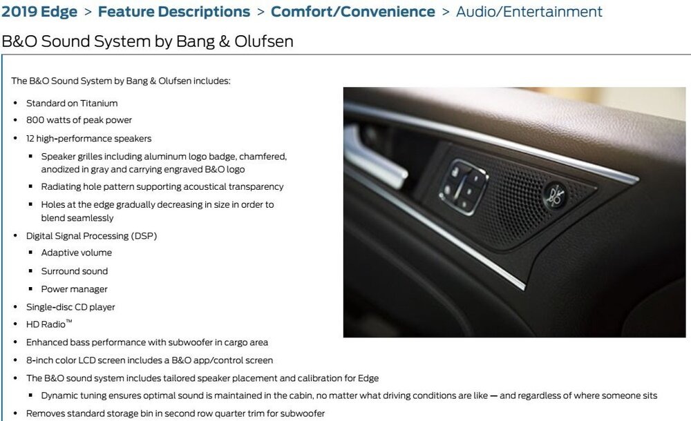 1 point
 -
Until your pads/brakes heat up, you can't brake and then don't have anything left to pick.1 point
-
if driving all day only gets the battery to 70%, i'd be checking alternator current output. and crank on every single power hungry accessory immediately after start up while watching the output, see if it hits a threshold below its actual spec. otherwise its possible the battery is just tired.1 point
-
Update: I got a new left steering wheel switch. SW-8186 (HG9Z-9C888-BB). This does not have lane centering. It is similar to the switch on the 2018 Edge with ACC and no lane centering. Once installed, I had to play around in SCCM with forescan. Option number 25 worked under the steering wheel left side switch. I know have ACC working, the switch allows me to change the distance setting. No error codes. The only limitation is no Stop and Go. Which I never use anyway.1 point
-
They are all LED Taillights, it is just how they illuminate that differentiates "Low" and "High" lines. Just out of curiosity and for confirmation @ADHCpilot, is your rear signal lights amber or red? I couldn't find a picture online to confirm what the "Low" line (SE, SEL, ST-Line) has in the rear.1 point